Archive
Demolition Engineering – Load Testing
I am conducting my Phase 3 at Wentworth House Partnership (WHP) who are the in house design office for Keltbray Group (KG), a specialist contractor with varying business units from demolition, through piling, to rail. About 75% of WHPs workload is from KG, the remainder is for non-competitors. Demolition is KGs biggest sector, hence the majority of WHP’s work, and my work to date, is to do with demolition.
The usual method of demolition in urban areas is top down demolition, which is essentially construction in reverse. Due to the construction techniques that were prevalent in the post war years, the majority of demolition is currently that of multi-storey reinforced concrete buildings.
To facilitate this form of demolition, plant is lifted to the top floor of the building and methodically demolishes the building one floor at a time, usually using the lift shafts as a drop zone for debris. The larger the machine is, the quicker (and therefore generally cheaper) the demolition process is.
The loads imposed on a structure during demolition are generally larger than the building was designed to accommodate. The loads come from demolition debris, plant used and changes in load paths by removing structural elements.
Removing structural elements and using heavy plant on suspended floors presents two main engineering challenges; determining the load capacity of the floor plates to size the machine that can be used, and ensuring that the building remains stable during demolition. This blog will outline the various methods that I have used for determining the capacity of the floors.
Option 1 – Allowable floor loads.
If the original purpose of the building and the year of construction are known, the relevant floor loading can be found from the codes which were in force at that time of construction. This is clearly the simplest approach, but it has two main drawbacks. Firstly, you have to ensure that no modifications have been made to the building, usually requiring time consuming opening up works. Secondly it is very conservative, resulting in either lots of back propping to mobilise the capacity of several floors, or smaller machines being used resulting in inefficient demolition. Engineering judgement allows the floor capacity to be increased by calculating the weight of non-structural finishes, partition walls, plant, etc., which will be removed prior to demolition. Additional capacity can be proven through knowledge of the safety factors that were used, under the BS factors were 1.4 for dead loads and 1.6 for live loads. Even with both of these methods, this option is still very conservative.
Option 2 – Back-analysis of structure.
It is possible to assess the floor to current standards to determine the capacity. However this relies on either original drawings existing, or time consuming opening up works being conducted. Currently I have only worked on one project where some drawings existed and assumptions were made (and communicated to the client) based on these. On other jobs, I have had to use the code of the period of construction to identify the minimum area of steel, cover, material properties, etc., and then use current codes to design based on this. Again, this is a very conservative technique.
Option 3 – Load Testing.
It is acknowledged that the design capacity of a structure is a lower bound value for the strength and that there may well be significant additional strength as a consequence of rational design, conservative assumptions in design and material strength issues. Large scale load testing can be used in order to establish what this additional strength is.
There are no standards for the structural testing of buildings during demolition. The approach that I have used is to select bays that are to be demolished and to test these to a load that represents the applied load from the demolition, with a suitable factor of safety. The factors applied to the load are 2.5 for flexural testing and 3.0 for shear testing.
Generally there are 5 common failure mechanisms for reinforced concrete buildings; flexural, beam shear, punching shear, buckling and progressive collapse. My experience suggests that most demolition projects involve flat slabs, built before the lessons were learnt from Ronan Point, so punching shear and the potential for disproportionate collapse are usually the limiting factors.
When I have specified load testing, I have used the approach shown in Figure 1. This consists of 3 separate types of test, all conducted in separate bays, selected for their uniformity across the project.
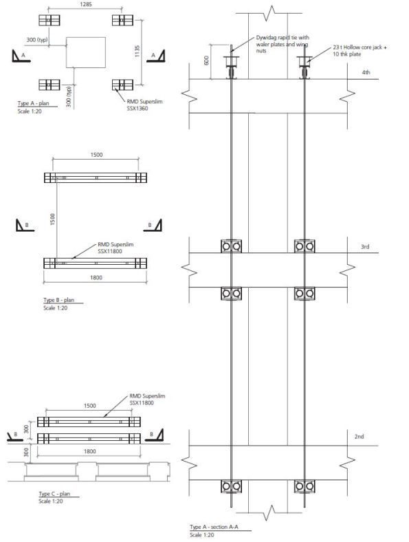
Figure 1. Load Testing Arrangements.
All tests follow the same basic set up; jacks are positioned on beams (generally sections on RMD super slim soldiers) which are tied to a number of floors below to achieve the required mass to jack against. The jacks can be propped from above instead of tied from below, but the props require large sections to resist buckling when compared to a 15mm diameter bar which is rated to 9t in tension. The specifics of each test is below:
Test Type A:
This is designed to test the capacity of the concrete columns. The test checks punching shear at the column faces in order to ensure that the excavator does not punch through the slab at these points. Set up shown in Figure 2.
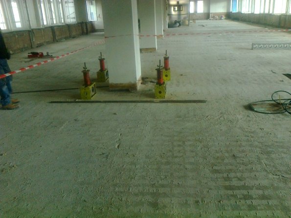
Figure 2. Test Type A.
Type B:
The Type B test is designed to test the capacity of the concrete slab and will take place at the point generating the largest moment and shear actions. The proposed testing will check flexural and shear strength in order to ensure the excavator does not fail the slab at these points.
Type C:
The Type C test is designed to test the capacity of the walls or edge columns. The proposed testing will check punching shear at the edge columns and the face of the wall in order to ensure that the excavator does not punch through the slab at these points.
Outcome
Generally option 1 and 2 are conducted, and unless a minimum of 8t machine (actually 9.6t with demolition equipment attached) is able to be used on the slab, load testing is requested. Load testing is time consuming, but it can generally be conducted during soft strip and has the potential of allowing a far larger machine to be used, saving much time in the process. When all three options have been used and the required capacity has not been achieved, the slab will be back-propped to a number of floors below to achieve the required capacity. Back-propping is time consuming and resource intense, so the fewer levels of back propping the better. As a matter of course, KG back-prop at least one level around all columns to mitigate punching shear.
Reflection
Load tests generally result in the floor having a capacity of circa 300% of the design value. Some of this accounted for by rational design, conservative assumptions in design and material strength, as stated earlier. I have identified the following additional reasons.
‘Non-structural’ screed
Most slabs have 50mm of screed on top. This is taken into account in the self-weight, but is neglected from structural calculations. In reality, screed does possess significant compressive strength. When the compressive region of the slab is on the top, which is usually the case, this screed increases the lever arm of the slab, increasing the capacity.
Ultimate limit state
Demolition engineering is not concerned with serviceability limit states, although there are exceptions, such as partial demolitions. Cracking in the tension zone is not a concern if the building is being demolished. This allows far greater loads to be applied whilst maintaining structural stability.
If anyone has any extra theories as to why structures are so much stronger than their design suggests then I would be interested to hear them.
300 George Street Site Introduction
Hello all no technical content in this blog just a quick project overview and introduction to my site, future posts will outline specific issues etc. that come up. I won’t dwell on the admin and challenges of actually getting out here suffice to say the “Beast from the East” couldn’t have chosen a less opportune time to hit the UK. My thanks to all who helped pick up the pieces of my carefully laid plans.
Location:
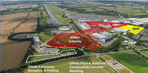
300 George Street is located in the heart of the Central Business District (CBD) in Brisbane Australia. It is a whole city centre block redevelopment tightly boarded by four busy lanes of traffic with the Brisbane River running just to its South West.

Figure 1 – Site Location
The project:
I am attached to Multiplex on the 300 George Street Project site in the heart of the Central Business District, Brisbane, Australia. The site is large vertically but takes up only a single city block approximately 100x80m. The project consists of a 3 floor retail/hotel podium above ground that links three separate towers; hotel; commercial; residential as shown by Figure 2&3 below.
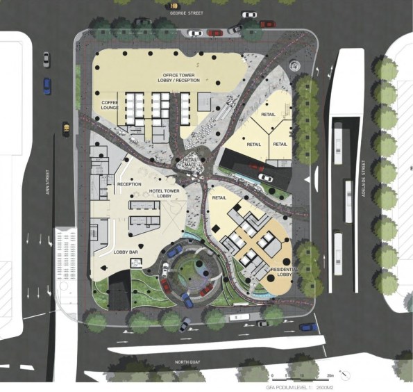
Figure 2 – Artists impression plan view of project showing the different sectors on the final construction.
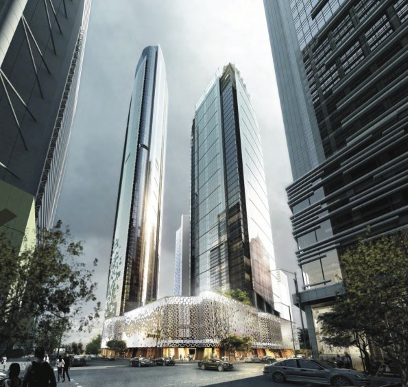
Figure 3 – Artists impression of completed structure from the corner of George & Adelaide Street. Residential tower to the left, Commercial tower to the right and Hotel tower to the rear.
Tower 1 – Hotel:
Tower one is the 34 floor luxury W Hotel complete with conference, spa and gym facilities. It is structurally complete with its final stage of E&M fit out well underway, the first levels are due to be handed over by the end of the month with the hotel set to open its doors around 1 June 2018. The internal finish is very impressive and it is clear the hotel is set to be a very high quality 5 star establishment.
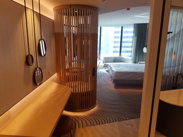
Figure 4 – The inside of one of the completed “basic” rooms, curtains, lights and sound system all electronically controlled from pads set into the walls.
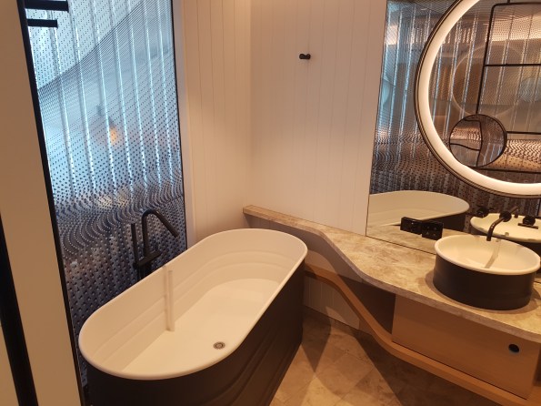
Figure 5 – Standard bathroom, shower and toilet to the right out of shot.
Tower 2 – Commercial:
Tower two will be a 40 floor commercial tower which will house a number of office spaces. Its superstructure is still being formed with a traditional slip formed core up to level 18 and decks to a few levels below this.
Tower 3 – Residential:
Tower three will be an 82 floor luxury residential tower however for now it is just a small concrete core barely sticking up out of the top of the podium. Work has yet to start on this tower due to the way the client has chosen to stage and let the contracts for the site. Multiplex are currently tendering for the contract to build this tower with the announcement due to be made shortly. There is clearly no guaranty they will win it and this possibility is causing some angsts due to the possibility of having to fit another primary contractor onto an already heavily congested site. Should Multiplex win the contract they are proposing a non-traditional method of construction that will supposedly see the core and decks being formed simultaneously. Figure 6 shows the current state of construction for the various areas.
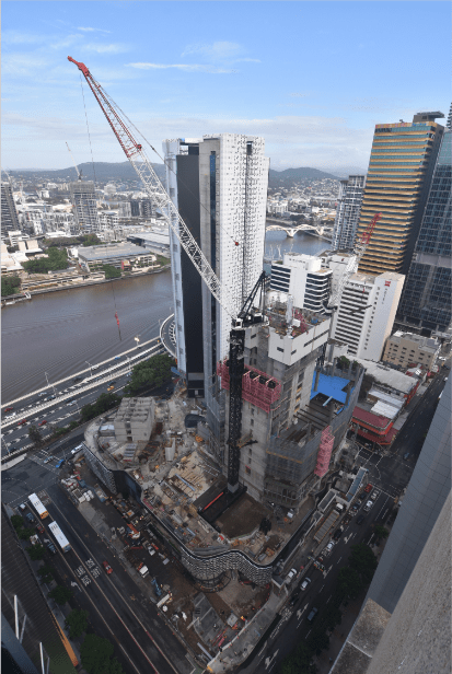
Figure 6 – Construction progress as at 21/03/2018 viewed from above the corner of Adelaide Street (perpendicular to river) and George Street (parallel to river). Hotel tower complete bar cladding in the rear, Commercial tower being slip formed and decked to the right, Residential tower not yet started but the start of the core visible to the left.
Basements:
Figure 7 shows that below ground 7 levels of basement have already been completed and partially handed over. This area is comprised of car parks, hotel back of house facilities and services/plant rooms.
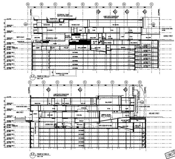
Figure 7 – Construction drawings showing two sections through the Podium and Basement.
Conclution:
Hopefully this has been of some interest in terms of base lining my site. I think the site is an interesting one and should provide plenty of opportunity to gain experience. I already have some ideas for future posts/AER/TMRs as time allows:
– Australian approach to H&S
– Digital document management
Bridge Design Using Microstran
Phase 3 has been useful in drawing on my experiences from Phase 2 to apply to the design of bridges, in particular their foundations, and large diameter piles.
John Holland have employed me as design coordinator which has allowed me to design parts of a 261m access bridge to a rail stock maintenance facility inconjunction with the structural consultant, BG&E. The curved bridge has 8 spans, with 2 x 4.0m lanes and 2 x 0.5m shoulders. The girders are 1525mm deep PSC super T’s supporting a 200mm cast in-situ continuous deck. Each super T is supported by an elastomeric bearing. The piers are supported on one single 2100mm dia driven steel tube, bored to the point of negligible bending moment.
The set out of the bridge was completed in AutoCad by the architect, Arcitectus. I then exported the .dwg file to a .dxf file to import into the structural software, Microstran Advanced V9. I then added nodes, line properties and interactions to build up a 3D structural model of the bridge (Figure 1). 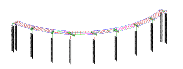
Figure 1 – Idealised Microstran 3D model of structure
The deck-super T connection is rigid, allowing loads to be laterally redistributed between super T’s longitudinally and transversely. The load transfer and redistribution depends on the stiffness of both structural elements and the supporting ground. Longitudinally the structure ‘floats’ on elastomeric bearings, longitudinal loads are shared between piers due to the bearing shear stiffness of the elastomeric bearings. The connection between the super T and headstock is modelled as a line with equivalent stiffness as the elastomeric bearings stiffness. This approach correctly models the interaction between superstructure and substructure of the bridge. The deck is restrained laterally by restraint blocks transferring load into the piers and abutments. HDPE plates are provided between the restraint block and girder to prevent concrete bearing on concrete. Load sharing affects the design of piers, piles, bearings and movement joints.
With guidance from BG&E, I was able to create a deck grillage model with appropriate longitudinal and transverse stiffness’s for the deck slab and girders to determine the design actions due to variable loads in the superstructure and substructure. Load cases were assigned to the bridge as per AS 5100; Permanent; Super imposed permanent; Footpath; Breaking; Centrifugal; Collision; Pedestrian; Shrinkage; and Creep. This model has been used to determine the design actions due to gravity and horizontal loads in the substructure. I then passed these values to the geotechnical engineer, SMEC, for pile design and expected settlement.
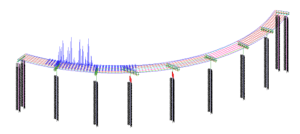
Figure 2 – Load model
Serviceability Limit State
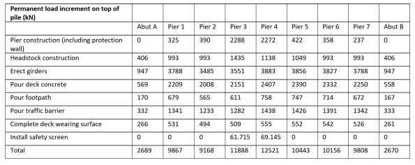
Serviceability deflections are critical for construction. During construction the loads on the piles progressively increase. I have broken down these loads so that the geotechnical engineer can calculate the settlement at each stage of construction. The bearings under the girders are set to levels by the use of a cementitious grout pad below the bearing, these can be adjusted to give the final surface level within serviceability limits.
Table 1 – Permanent load increments on top of each pile during construction stages
Lateral Soil Springs
The structural model needs to be supported, pinned or fixed supports are not realistic, soil springs are used to represent the pile-soil interaction and are applied along the length of the piles. The springs stiffness represents the lateral stiffness of the soil in that location modelling the pile-soil interaction. The behaviour of springs is predictable to understand and can be incorporated into Microstran.
As soil behaviour is nonlinear spring stiffness depends on geometry and load. The relationship between the structural and geotechnical engineer is therefore iterative. Structural engineers require a spring constant, but the modulus of subgrade reaction is highly variable with geometry and load. Geotechnical engineers require deflections under known loads and geometry. This though depends on the foundation stiffness. I have been managing the channels of communication between the structural and geotechnical engineer.
Checks are required as to whether soil passive limits are reached. If so, this is where deflection is greatest at the top of the pile, and the affected springs are removed and replaced with a force equal to the passive limit.

Figure 3 – Inputting spring constants provided by the geotechnical engineer into Microstran
Jaguar Land Rover – Noise Vibration and Harshness Project
Keen to hear some thoughts on the structural design vs. buildability of a concrete-steel connection detail that has been generating much discussion throughout my whole project team!
–
Context
Jaguar Land Rover are spending big in their heartland here in the West Midlands. The main Research and Development site is very close to MOD Kineton in Gaydon. The former British Leyland campus has been developed from an old Vulcan bomber runway into a series of test tracks and supporting facilities.
Laing O’Rourke have close to £400m of work and I am part of their Expanded Structures engineering team on the Noise, Vibration and Harshness (NVH) project.
A last minute change of contractor by the client, and no extension to the delivery date means this D&B contract is running very hot.
–
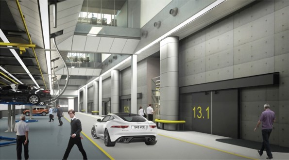
In order to outmatch the German and Japanese markets, JLR want to be sure they have increased build quality in their cars. For this a new NVH facility is required that will resemble a high-tech laboratory for cars. 30 No. individual testing cells will see vehicles on rolling roads pushed to their limits within isolated and unique environmental conditions.
Ridge Consultants have designed a ‘box within a box’ concept to ensure the vibrations from testing are not transferred to the structural frame. LOR are using their own pre-cast system called ‘Twin Wall’ to form the cells and a steel frame will house the whole facility with internal roads and office space.

Twin wall is a double skinned pre-cast system in which a cavity is filled with concrete once positioned on site. There are a host of quality and logistical benefits to using this method but it now gives us a buildability challenge with a concrete-steel connection.
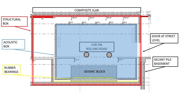
Typical section of a vehicle test cell.
Large RC seismic blocks sit on a bed of rubber bearings. The rolling road plant is fixed to this to prevent excess vibration transfer to the structure.
Structural box is formed from twin wall with composite slab roof.
Acoustic inner box is also formed from twin wall with composite slab roof formed inside steel webs to create flush finish.
Build sequence is;
- Lay rubber bearings
- Cast seismic block
- Erect Structural Twin Wall
- Cast Acoustic base slab
- Erect Acoustic Twin Wall
- Fix steel beams
- Cast composite roof slab
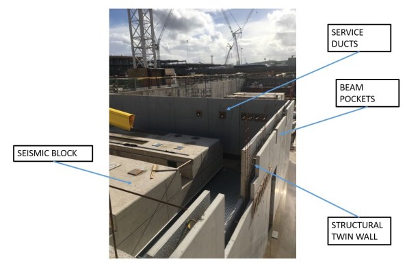
So far we have just positioned the first set of structural twin wall. In the progress photo you can see the service ducts and beam pockets that have been formed in the pre-cast leaf of twin wall.
The Acoustic wall will sit in between the structural wall and the seismic block.
–
Issue
Some of the spans are 14m and so large UKB 1016 x 305 x 272 have been pre-cambered. The structural engineer at Ridge has designed the steel primary beams as a pinned connection to allow the camber to drop out upon loading of the wet concrete composite slab.
As the designer didn’t understand the build sequence of the twin wall, they assumed these beams would have full bearing of 145mm at either end upon loading. However, the top infill of twin wall is typically cast at the same time as the composite slab it supports.
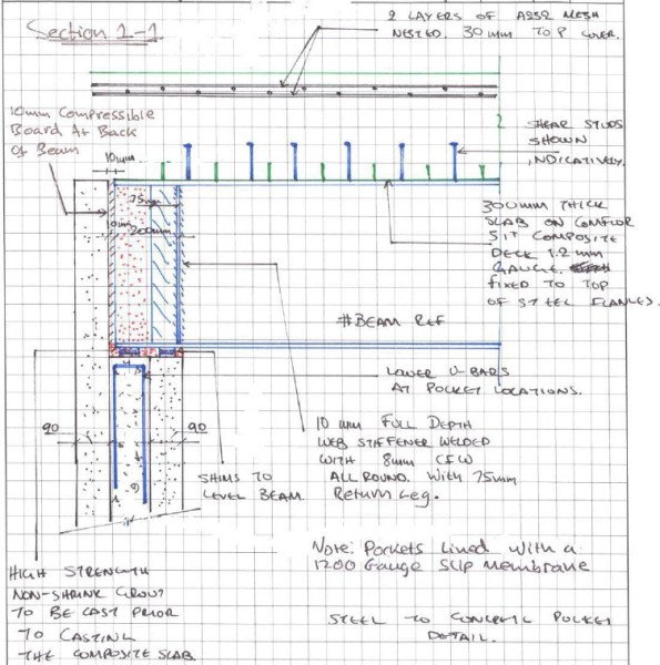
The designer proposes a shuttered pocket forming a void within the infill concrete pour to top level of wall. Packing shims are then placed before landing the beam and adding a layer of non-shrink grout. Flexible boarding behind the beam is then positioned and the remainder of the void infilled with more grout. All this shuttering and small grout pours are proposed to be at the top of twin wall panels 7.7m above ground. It is not practical for this detail to be implemented on site. We have in excess of 300 of these concrete-steel connections to form and that creates a significant amount of repeat visit, working at height activities. We seek a solution to reduce this by refining the detail.
–
Our concept is to land the steel on a full width shim that is fixed with resin to the outer leaf of the twin wall with the cavity only partially filled. The end of the beam would be wrapped in a flexible membrane to allow the pinned connection to form once we pour the composite deck and final lift of twin wall infill as a single pour.

We are waiting for the structural designers to check if the bearing in this case is acceptable as in the temporary state the 90mm leaf of twin wall carries the full load. See my concept below;

I ran some numbers so I could compare with their results;
Beam
UKB 1016 x 305 x 272 = 272kg/m
WL/2 * 1.35= 26kN
Slab
Wet concrete = 26 kN/m3
Depth = 0.3m
Beam centres = 4.0m
26 x 0.3 x 4.0 = 31.2 kN/m
WL/2 * 1.35 = 295kN
Construction Loads
Q = 1.0kN/m2
WL/2 * 1.5 = 42kN
Total Bearing
Beam + Slab + Construction = 363kN
| Bearing (N) | Shim (mm) | Area (mm2) | Pressure (N/mm2) |
| 363,000 | 145×305 | 44225 | 8.21 |
| 90×305 | 27450 | 13.22 | |
| 60×305 | 18300 | 19.84 | |
| (60×60)x2 | 7200 | 50.42 |
Concrete is C40/50 (50N/mm2) and so by my reckoning, even if we place a 60mm shim beneath the steel, the bearing on the twin wall leaf would be less than the capacity of the concrete.
- Does that bearing capacity sound right?
- Any other ideas how we could de-bond the steel and so form a pinned connection whilst seeking to minimise work at height?
–
There are other interesting challenges for us to overcome that I might blog about in time;
- Passing services between the test cell and main structure without transferring vibration. (See my detail above with initial concept).
- Calculating the amount of settlement to allow for in the rubber bearings so we don’t set the road level too high / low.
Can you under-sling a DROPS rack?
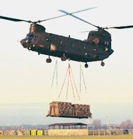
I have been asked to look into designing a system that would allow a lorry loaded with supplies to pull up under a crane, and have all its stores unloaded in a single lift. This could range from a full load of rebar, to a single machine, weighing up to 15t.
The purpose is to speed up unloading so that the crane can get on with construction, and to remove the lorry from site sooner, as logistics and unloading spaces are tight.
Does anyone know if you can under-sling a DROPS rack? I am relatively sure that the APFB comes on a DROPS rack, and clearly that can be under slung, but I am not sure of the maximum load that rack could carry like this (ignoring the limitation of the hook, the crane is perfectly capable of the loads required.)
I have trawled through the BA Battlebox logistic pamphlets but with no luck. I know that the DROPS can carry 15t and has a self weight of 1.5t, but I do not know if this capacity would reduce if lifted by a crane and not loaded onto a lorry.
Any suggestions?
