Archive
Jaguar Land Rover – Noise Vibration and Harshness Project
Keen to hear some thoughts on the structural design vs. buildability of a concrete-steel connection detail that has been generating much discussion throughout my whole project team!
–
Context
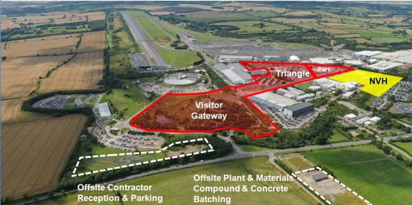
Jaguar Land Rover are spending big in their heartland here in the West Midlands. The main Research and Development site is very close to MOD Kineton in Gaydon. The former British Leyland campus has been developed from an old Vulcan bomber runway into a series of test tracks and supporting facilities.
Laing O’Rourke have close to £400m of work and I am part of their Expanded Structures engineering team on the Noise, Vibration and Harshness (NVH) project.
A last minute change of contractor by the client, and no extension to the delivery date means this D&B contract is running very hot.
–
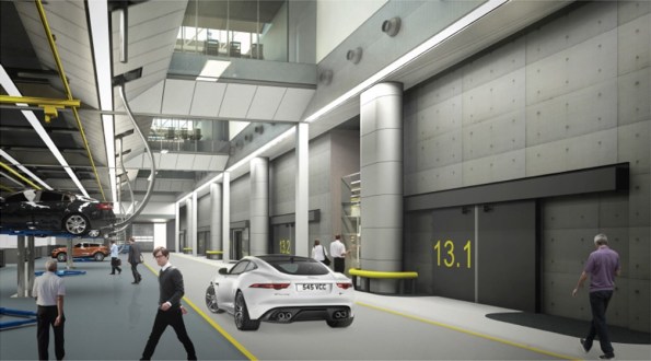
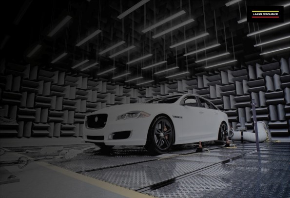
In order to outmatch the German and Japanese markets, JLR want to be sure they have increased build quality in their cars. For this a new NVH facility is required that will resemble a high-tech laboratory for cars. 30 No. individual testing cells will see vehicles on rolling roads pushed to their limits within isolated and unique environmental conditions.
Ridge Consultants have designed a ‘box within a box’ concept to ensure the vibrations from testing are not transferred to the structural frame. LOR are using their own pre-cast system called ‘Twin Wall’ to form the cells and a steel frame will house the whole facility with internal roads and office space.
Twin wall is a double skinned pre-cast system in which a cavity is filled with concrete once positioned on site. There are a host of quality and logistical benefits to using this method but it now gives us a buildability challenge with a concrete-steel connection.
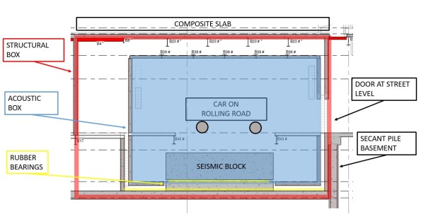
Typical section of a vehicle test cell.
Large RC seismic blocks sit on a bed of rubber bearings. The rolling road plant is fixed to this to prevent excess vibration transfer to the structure.
Structural box is formed from twin wall with composite slab roof.
Acoustic inner box is also formed from twin wall with composite slab roof formed inside steel webs to create flush finish.
Build sequence is;
- Lay rubber bearings
- Cast seismic block
- Erect Structural Twin Wall
- Cast Acoustic base slab
- Erect Acoustic Twin Wall
- Fix steel beams
- Cast composite roof slab
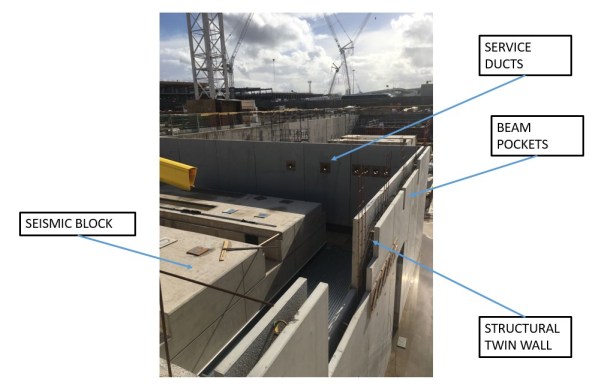
So far we have just positioned the first set of structural twin wall. In the progress photo you can see the service ducts and beam pockets that have been formed in the pre-cast leaf of twin wall.
The Acoustic wall will sit in between the structural wall and the seismic block.
–
Issue
Some of the spans are 14m and so large UKB 1016 x 305 x 272 have been pre-cambered. The structural engineer at Ridge has designed the steel primary beams as a pinned connection to allow the camber to drop out upon loading of the wet concrete composite slab.
As the designer didn’t understand the build sequence of the twin wall, they assumed these beams would have full bearing of 145mm at either end upon loading. However, the top infill of twin wall is typically cast at the same time as the composite slab it supports.
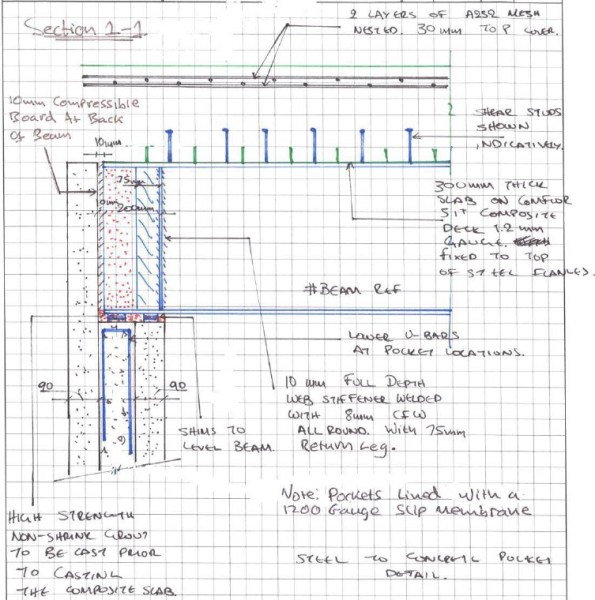
The designer proposes a shuttered pocket forming a void within the infill concrete pour to top level of wall. Packing shims are then placed before landing the beam and adding a layer of non-shrink grout. Flexible boarding behind the beam is then positioned and the remainder of the void infilled with more grout. All this shuttering and small grout pours are proposed to be at the top of twin wall panels 7.7m above ground. It is not practical for this detail to be implemented on site. We have in excess of 300 of these concrete-steel connections to form and that creates a significant amount of repeat visit, working at height activities. We seek a solution to reduce this by refining the detail.
–
Our concept is to land the steel on a full width shim that is fixed with resin to the outer leaf of the twin wall with the cavity only partially filled. The end of the beam would be wrapped in a flexible membrane to allow the pinned connection to form once we pour the composite deck and final lift of twin wall infill as a single pour.

We are waiting for the structural designers to check if the bearing in this case is acceptable as in the temporary state the 90mm leaf of twin wall carries the full load. See my concept below;

I ran some numbers so I could compare with their results;
Beam
UKB 1016 x 305 x 272 = 272kg/m
WL/2 * 1.35= 26kN
Slab
Wet concrete = 26 kN/m3
Depth = 0.3m
Beam centres = 4.0m
26 x 0.3 x 4.0 = 31.2 kN/m
WL/2 * 1.35 = 295kN
Construction Loads
Q = 1.0kN/m2
WL/2 * 1.5 = 42kN
Total Bearing
Beam + Slab + Construction = 363kN
| Bearing (N) | Shim (mm) | Area (mm2) | Pressure (N/mm2) |
| 363,000 | 145×305 | 44225 | 8.21 |
| 90×305 | 27450 | 13.22 | |
| 60×305 | 18300 | 19.84 | |
| (60×60)x2 | 7200 | 50.42 |
Concrete is C40/50 (50N/mm2) and so by my reckoning, even if we place a 60mm shim beneath the steel, the bearing on the twin wall leaf would be less than the capacity of the concrete.
- Does that bearing capacity sound right?
- Any other ideas how we could de-bond the steel and so form a pinned connection whilst seeking to minimise work at height?
–
There are other interesting challenges for us to overcome that I might blog about in time;
- Passing services between the test cell and main structure without transferring vibration. (See my detail above with initial concept).
- Calculating the amount of settlement to allow for in the rubber bearings so we don’t set the road level too high / low.
