Jaguar Land Rover – Noise Vibration and Harshness Project
Keen to hear some thoughts on the structural design vs. buildability of a concrete-steel connection detail that has been generating much discussion throughout my whole project team!
–
Context
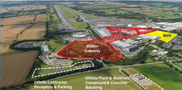
Jaguar Land Rover are spending big in their heartland here in the West Midlands. The main Research and Development site is very close to MOD Kineton in Gaydon. The former British Leyland campus has been developed from an old Vulcan bomber runway into a series of test tracks and supporting facilities.
Laing O’Rourke have close to £400m of work and I am part of their Expanded Structures engineering team on the Noise, Vibration and Harshness (NVH) project.
A last minute change of contractor by the client, and no extension to the delivery date means this D&B contract is running very hot.
–
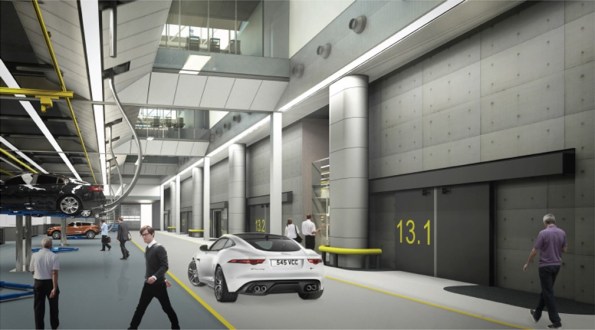
In order to outmatch the German and Japanese markets, JLR want to be sure they have increased build quality in their cars. For this a new NVH facility is required that will resemble a high-tech laboratory for cars. 30 No. individual testing cells will see vehicles on rolling roads pushed to their limits within isolated and unique environmental conditions.
Ridge Consultants have designed a ‘box within a box’ concept to ensure the vibrations from testing are not transferred to the structural frame. LOR are using their own pre-cast system called ‘Twin Wall’ to form the cells and a steel frame will house the whole facility with internal roads and office space.

Twin wall is a double skinned pre-cast system in which a cavity is filled with concrete once positioned on site. There are a host of quality and logistical benefits to using this method but it now gives us a buildability challenge with a concrete-steel connection.
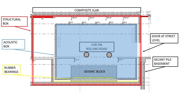
Typical section of a vehicle test cell.
Large RC seismic blocks sit on a bed of rubber bearings. The rolling road plant is fixed to this to prevent excess vibration transfer to the structure.
Structural box is formed from twin wall with composite slab roof.
Acoustic inner box is also formed from twin wall with composite slab roof formed inside steel webs to create flush finish.
Build sequence is;
- Lay rubber bearings
- Cast seismic block
- Erect Structural Twin Wall
- Cast Acoustic base slab
- Erect Acoustic Twin Wall
- Fix steel beams
- Cast composite roof slab
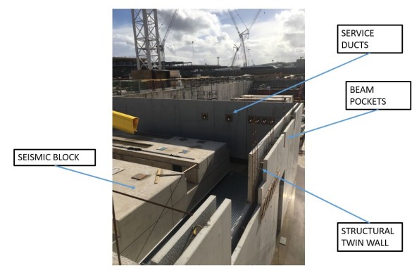
So far we have just positioned the first set of structural twin wall. In the progress photo you can see the service ducts and beam pockets that have been formed in the pre-cast leaf of twin wall.
The Acoustic wall will sit in between the structural wall and the seismic block.
–
Issue
Some of the spans are 14m and so large UKB 1016 x 305 x 272 have been pre-cambered. The structural engineer at Ridge has designed the steel primary beams as a pinned connection to allow the camber to drop out upon loading of the wet concrete composite slab.
As the designer didn’t understand the build sequence of the twin wall, they assumed these beams would have full bearing of 145mm at either end upon loading. However, the top infill of twin wall is typically cast at the same time as the composite slab it supports.
The designer proposes a shuttered pocket forming a void within the infill concrete pour to top level of wall. Packing shims are then placed before landing the beam and adding a layer of non-shrink grout. Flexible boarding behind the beam is then positioned and the remainder of the void infilled with more grout. All this shuttering and small grout pours are proposed to be at the top of twin wall panels 7.7m above ground. It is not practical for this detail to be implemented on site. We have in excess of 300 of these concrete-steel connections to form and that creates a significant amount of repeat visit, working at height activities. We seek a solution to reduce this by refining the detail.
–
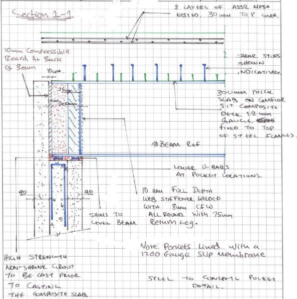
Our concept is to land the steel on a full width shim that is fixed with resin to the outer leaf of the twin wall with the cavity only partially filled. The end of the beam would be wrapped in a flexible membrane to allow the pinned connection to form once we pour the composite deck and final lift of twin wall infill as a single pour.

We are waiting for the structural designers to check if the bearing in this case is acceptable as in the temporary state the 90mm leaf of twin wall carries the full load. See my concept below;

I ran some numbers so I could compare with their results;
Beam
UKB 1016 x 305 x 272 = 272kg/m
WL/2 * 1.35= 26kN
Slab
Wet concrete = 26 kN/m3
Depth = 0.3m
Beam centres = 4.0m
26 x 0.3 x 4.0 = 31.2 kN/m
WL/2 * 1.35 = 295kN
Construction Loads
Q = 1.0kN/m2
WL/2 * 1.5 = 42kN
Total Bearing
Beam + Slab + Construction = 363kN
| Bearing (N) | Shim (mm) | Area (mm2) | Pressure (N/mm2) |
| 363,000 | 145×305 | 44225 | 8.21 |
| 90×305 | 27450 | 13.22 | |
| 60×305 | 18300 | 19.84 | |
| (60×60)x2 | 7200 | 50.42 |
Concrete is C40/50 (50N/mm2) and so by my reckoning, even if we place a 60mm shim beneath the steel, the bearing on the twin wall leaf would be less than the capacity of the concrete.
- Does that bearing capacity sound right?
- Any other ideas how we could de-bond the steel and so form a pinned connection whilst seeking to minimise work at height?
–
There are other interesting challenges for us to overcome that I might blog about in time;
- Passing services between the test cell and main structure without transferring vibration. (See my detail above with initial concept).
- Calculating the amount of settlement to allow for in the rubber bearings so we don’t set the road level too high / low.

Hello Joe great blog straight out the gate!
I think your total load is a little low? Beam (26) + Slab (295) + Construction (42) = 363kN Not sure if I have miss understood apologies if I have, by my math this doesn’t effect your conclusion anyway so the point is moot.
I’m not sure I understand the function of the shims as I can’t get the same areas you’re quoting. By my reckoning all the shims can do is provide a wearing surface to prevent the concrete in contact with the beam from degrading. They are too thin to be able to spread out the load and give you a greater contact area, thereby reducing the bearing pressure, aren’t they? Can you set me straight?
I calculated your contact area as 90mm (width of single leaf of twin wall) x 300mm (beam width) = 27,000mm^2 i.e. this concrete must be able to take the total load from the beam.
Resulting bearing pressure being 363000 / 27000 = 13.4N/mm^2 > 30N/mm^2 therefore like you it looks to me like C30/40 concrete should be able to withstand this load.
I wonder if we are over simplifying this though as horizontal loads haven’t been dealt with although I can’t see any significant loading coming from the beam to be transferred to the twin wall. Interested to hear what your designers come back with.
Also are there not some design life issues by supporting the beam in this method? Metal on metal contact that is designed to move against each other will take the paint off and expose metal allowing rust to start attacking it? Is this not something akin to a bridge beam (i.e needing bearings)?
With ref to the debonding would a thick shuttering oil do the job quicker?
Ben,
Shims just level up the pre-cast concrete before grout / concrete flows underneath beam. Before that grouting they provide a much smaller surface area for bearing (greater pressure). My concern was that this would cause spalling or failure in the twin wall concrete in the temporary state.
Correct with how I calculated area. Shim width x beam flange.
Not sure how I added up those loads but yes you are correct, it should be 363kN.
The beam has its compression flange restrained so good to see there’s no chance of LTB. Has the designer looked at including web stiffeners to prevent shear failure on the web of the UKB?
To support the beam, how about plastic packers which can be increased in 1 or 2mm intervals to overcome buildability issues or an elastomeric bearing?
Could you surround it with polystyrene during the pour to allow it to continue acting like a pin when in service?
Morning Joe,
Thanks for the blog – sounds like an interesting project. Agree with you interpretation of bearing in the temporary case and the comments by Ben. I don’t know much about twin wall but wondered what the connection between panels is like. As in, if you have more than one twin wall stacked on each other and you haven’t filled the void is there any stability issues trying to land these beams on the top twin wall – especially with the possibility of an accidental load during positioning the beam?
Second point is on the reduction of working at height. Good to hear the design/construction team are thinking about how things are being constructed to reduce risk to the work force – all good evidence towards CPR. I might be missing something but if you are trying to achieve a pin connection could the twin wall not be amended to box out the beam pocket completely? This work could be done offsite/not a height, then the beam could be landed straight on using your proposal above. The pocket would then not be filled with concrete but the shear studs would provide lateral stability of the beam through the slab. The connection then only needs to be designed for shear as per the design intent. This would also removed the need for a lot of boxing out around each beam once installed before you pour.
James – looks like there’s a web stiffener shown on Section 1-1.
‘if you have more than one twin wall stacked on each other and you haven’t filled the void is there any stability issues’
I can’t think of an example in our build sequence where this occurs. If the walls are stacked, they are footed on an intermediary slab.
‘could the twin wall not be amended to box out the beam pocket completely? This work could be done offsite/not a height’
Was my first suggestion but apparently Explore (LOR precast) would not be willing to foot this expense. Although all subsidiaries of LOR, they operate very much like any regular supplier and would charge our site (Expanded Structures) a fortune for the variation. I would have thought with the same parent company, a better deal could have been struck but it seems the director of each business unit wants to show off the greatest profits to the board at year end…
http://www.laingorourke.com/engineering-the-future/product-and-process-innovation/eip.aspx
Video of explore’s factory.
Joe,
Looks like a great project for experience.
I would have thought, as James suggests this problem is limited by stability of the wall over pure compressive strength. If stability is an issue the beam can always be proper next support.
This might not go down well will the greens but a vertical shutter could be fixed to the beam at each end and lifted in. Polystyrene on the ends to give you the void former, leave tubes in the floor cast over the void.
Once the slab/beam deflects, pour a liquid which disolves polystyrene (disesel). Pour your high strength grout through the tube into the void. You would need some way of allowing the disesel to flow out but not grout. Dunno how.
Just a thought though.
I am pretty sure if you prepared the ends with some sort of de-bonded, the deflection would still occur without locking in to much stress.
Good blog.
Brad
I like the concept of removing the de-bonding membrane/foam/polystyrene. I think in this case we need to simplify the solution as much as possible but I’ll give you the credit if I steal that idea anywhere else!
In terms of stability, the wall panels are propped with push-pulls and there is a lattice at 300mm centres in the cavity. We are concerned about our 7.7m panels when they are exposed to wind loading. Going to increase the starter bars and change the build sequence so we can leave the props up for longer.