Archive
300 George Street Site Introduction
Hello all no technical content in this blog just a quick project overview and introduction to my site, future posts will outline specific issues etc. that come up. I won’t dwell on the admin and challenges of actually getting out here suffice to say the “Beast from the East” couldn’t have chosen a less opportune time to hit the UK. My thanks to all who helped pick up the pieces of my carefully laid plans.
Location:
300 George Street is located in the heart of the Central Business District (CBD) in Brisbane Australia. It is a whole city centre block redevelopment tightly boarded by four busy lanes of traffic with the Brisbane River running just to its South West.

Figure 1 – Site Location
The project:
I am attached to Multiplex on the 300 George Street Project site in the heart of the Central Business District, Brisbane, Australia. The site is large vertically but takes up only a single city block approximately 100x80m. The project consists of a 3 floor retail/hotel podium above ground that links three separate towers; hotel; commercial; residential as shown by Figure 2&3 below.
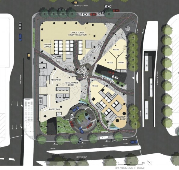
Figure 2 – Artists impression plan view of project showing the different sectors on the final construction.
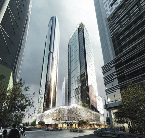
Figure 3 – Artists impression of completed structure from the corner of George & Adelaide Street. Residential tower to the left, Commercial tower to the right and Hotel tower to the rear.
Tower 1 – Hotel:
Tower one is the 34 floor luxury W Hotel complete with conference, spa and gym facilities. It is structurally complete with its final stage of E&M fit out well underway, the first levels are due to be handed over by the end of the month with the hotel set to open its doors around 1 June 2018. The internal finish is very impressive and it is clear the hotel is set to be a very high quality 5 star establishment.
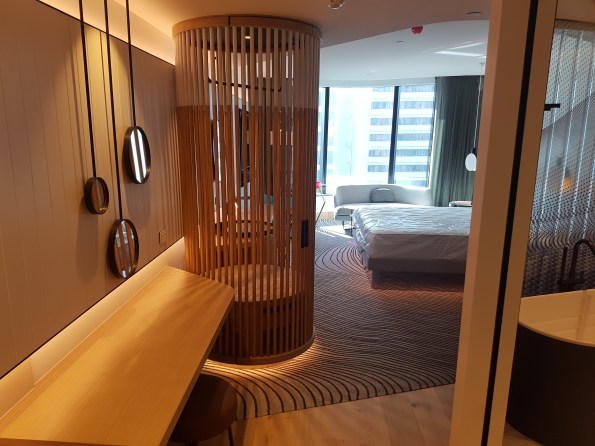
Figure 4 – The inside of one of the completed “basic” rooms, curtains, lights and sound system all electronically controlled from pads set into the walls.
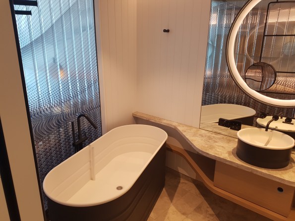
Figure 5 – Standard bathroom, shower and toilet to the right out of shot.
Tower 2 – Commercial:
Tower two will be a 40 floor commercial tower which will house a number of office spaces. Its superstructure is still being formed with a traditional slip formed core up to level 18 and decks to a few levels below this.
Tower 3 – Residential:
Tower three will be an 82 floor luxury residential tower however for now it is just a small concrete core barely sticking up out of the top of the podium. Work has yet to start on this tower due to the way the client has chosen to stage and let the contracts for the site. Multiplex are currently tendering for the contract to build this tower with the announcement due to be made shortly. There is clearly no guaranty they will win it and this possibility is causing some angsts due to the possibility of having to fit another primary contractor onto an already heavily congested site. Should Multiplex win the contract they are proposing a non-traditional method of construction that will supposedly see the core and decks being formed simultaneously. Figure 6 shows the current state of construction for the various areas.
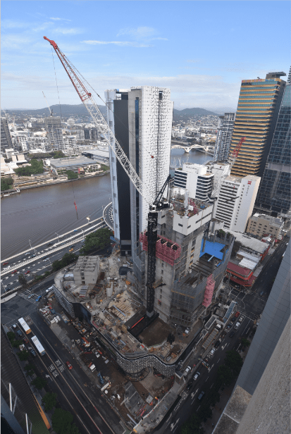
Figure 6 – Construction progress as at 21/03/2018 viewed from above the corner of Adelaide Street (perpendicular to river) and George Street (parallel to river). Hotel tower complete bar cladding in the rear, Commercial tower being slip formed and decked to the right, Residential tower not yet started but the start of the core visible to the left.
Basements:
Figure 7 shows that below ground 7 levels of basement have already been completed and partially handed over. This area is comprised of car parks, hotel back of house facilities and services/plant rooms.
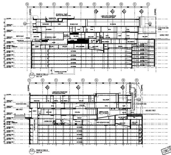
Figure 7 – Construction drawings showing two sections through the Podium and Basement.
Conclution:
Hopefully this has been of some interest in terms of base lining my site. I think the site is an interesting one and should provide plenty of opportunity to gain experience. I already have some ideas for future posts/AER/TMRs as time allows:
– Australian approach to H&S
– Digital document management
Bridge Design Using Microstran
Phase 3 has been useful in drawing on my experiences from Phase 2 to apply to the design of bridges, in particular their foundations, and large diameter piles.
John Holland have employed me as design coordinator which has allowed me to design parts of a 261m access bridge to a rail stock maintenance facility inconjunction with the structural consultant, BG&E. The curved bridge has 8 spans, with 2 x 4.0m lanes and 2 x 0.5m shoulders. The girders are 1525mm deep PSC super T’s supporting a 200mm cast in-situ continuous deck. Each super T is supported by an elastomeric bearing. The piers are supported on one single 2100mm dia driven steel tube, bored to the point of negligible bending moment.
The set out of the bridge was completed in AutoCad by the architect, Arcitectus. I then exported the .dwg file to a .dxf file to import into the structural software, Microstran Advanced V9. I then added nodes, line properties and interactions to build up a 3D structural model of the bridge (Figure 1). 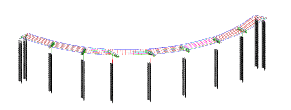
Figure 1 – Idealised Microstran 3D model of structure
The deck-super T connection is rigid, allowing loads to be laterally redistributed between super T’s longitudinally and transversely. The load transfer and redistribution depends on the stiffness of both structural elements and the supporting ground. Longitudinally the structure ‘floats’ on elastomeric bearings, longitudinal loads are shared between piers due to the bearing shear stiffness of the elastomeric bearings. The connection between the super T and headstock is modelled as a line with equivalent stiffness as the elastomeric bearings stiffness. This approach correctly models the interaction between superstructure and substructure of the bridge. The deck is restrained laterally by restraint blocks transferring load into the piers and abutments. HDPE plates are provided between the restraint block and girder to prevent concrete bearing on concrete. Load sharing affects the design of piers, piles, bearings and movement joints.
With guidance from BG&E, I was able to create a deck grillage model with appropriate longitudinal and transverse stiffness’s for the deck slab and girders to determine the design actions due to variable loads in the superstructure and substructure. Load cases were assigned to the bridge as per AS 5100; Permanent; Super imposed permanent; Footpath; Breaking; Centrifugal; Collision; Pedestrian; Shrinkage; and Creep. This model has been used to determine the design actions due to gravity and horizontal loads in the substructure. I then passed these values to the geotechnical engineer, SMEC, for pile design and expected settlement.
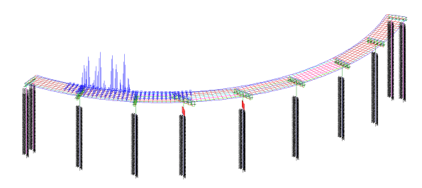
Figure 2 – Load model
Serviceability Limit State
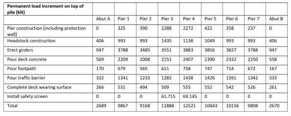
Serviceability deflections are critical for construction. During construction the loads on the piles progressively increase. I have broken down these loads so that the geotechnical engineer can calculate the settlement at each stage of construction. The bearings under the girders are set to levels by the use of a cementitious grout pad below the bearing, these can be adjusted to give the final surface level within serviceability limits.
Table 1 – Permanent load increments on top of each pile during construction stages
Lateral Soil Springs
The structural model needs to be supported, pinned or fixed supports are not realistic, soil springs are used to represent the pile-soil interaction and are applied along the length of the piles. The springs stiffness represents the lateral stiffness of the soil in that location modelling the pile-soil interaction. The behaviour of springs is predictable to understand and can be incorporated into Microstran.
As soil behaviour is nonlinear spring stiffness depends on geometry and load. The relationship between the structural and geotechnical engineer is therefore iterative. Structural engineers require a spring constant, but the modulus of subgrade reaction is highly variable with geometry and load. Geotechnical engineers require deflections under known loads and geometry. This though depends on the foundation stiffness. I have been managing the channels of communication between the structural and geotechnical engineer.
Checks are required as to whether soil passive limits are reached. If so, this is where deflection is greatest at the top of the pile, and the affected springs are removed and replaced with a force equal to the passive limit.

Figure 3 – Inputting spring constants provided by the geotechnical engineer into Microstran
