Bridge Design Using Microstran
Phase 3 has been useful in drawing on my experiences from Phase 2 to apply to the design of bridges, in particular their foundations, and large diameter piles.
John Holland have employed me as design coordinator which has allowed me to design parts of a 261m access bridge to a rail stock maintenance facility inconjunction with the structural consultant, BG&E. The curved bridge has 8 spans, with 2 x 4.0m lanes and 2 x 0.5m shoulders. The girders are 1525mm deep PSC super T’s supporting a 200mm cast in-situ continuous deck. Each super T is supported by an elastomeric bearing. The piers are supported on one single 2100mm dia driven steel tube, bored to the point of negligible bending moment.
The set out of the bridge was completed in AutoCad by the architect, Arcitectus. I then exported the .dwg file to a .dxf file to import into the structural software, Microstran Advanced V9. I then added nodes, line properties and interactions to build up a 3D structural model of the bridge (Figure 1). 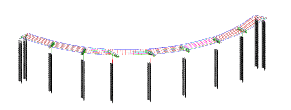
Figure 1 – Idealised Microstran 3D model of structure
The deck-super T connection is rigid, allowing loads to be laterally redistributed between super T’s longitudinally and transversely. The load transfer and redistribution depends on the stiffness of both structural elements and the supporting ground. Longitudinally the structure ‘floats’ on elastomeric bearings, longitudinal loads are shared between piers due to the bearing shear stiffness of the elastomeric bearings. The connection between the super T and headstock is modelled as a line with equivalent stiffness as the elastomeric bearings stiffness. This approach correctly models the interaction between superstructure and substructure of the bridge. The deck is restrained laterally by restraint blocks transferring load into the piers and abutments. HDPE plates are provided between the restraint block and girder to prevent concrete bearing on concrete. Load sharing affects the design of piers, piles, bearings and movement joints.
With guidance from BG&E, I was able to create a deck grillage model with appropriate longitudinal and transverse stiffness’s for the deck slab and girders to determine the design actions due to variable loads in the superstructure and substructure. Load cases were assigned to the bridge as per AS 5100; Permanent; Super imposed permanent; Footpath; Breaking; Centrifugal; Collision; Pedestrian; Shrinkage; and Creep. This model has been used to determine the design actions due to gravity and horizontal loads in the substructure. I then passed these values to the geotechnical engineer, SMEC, for pile design and expected settlement.
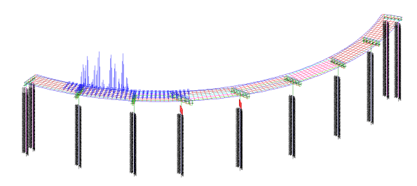
Figure 2 – Load model
Serviceability Limit State
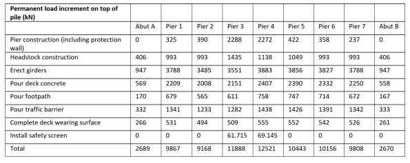
Serviceability deflections are critical for construction. During construction the loads on the piles progressively increase. I have broken down these loads so that the geotechnical engineer can calculate the settlement at each stage of construction. The bearings under the girders are set to levels by the use of a cementitious grout pad below the bearing, these can be adjusted to give the final surface level within serviceability limits.
Table 1 – Permanent load increments on top of each pile during construction stages
Lateral Soil Springs
The structural model needs to be supported, pinned or fixed supports are not realistic, soil springs are used to represent the pile-soil interaction and are applied along the length of the piles. The springs stiffness represents the lateral stiffness of the soil in that location modelling the pile-soil interaction. The behaviour of springs is predictable to understand and can be incorporated into Microstran.
As soil behaviour is nonlinear spring stiffness depends on geometry and load. The relationship between the structural and geotechnical engineer is therefore iterative. Structural engineers require a spring constant, but the modulus of subgrade reaction is highly variable with geometry and load. Geotechnical engineers require deflections under known loads and geometry. This though depends on the foundation stiffness. I have been managing the channels of communication between the structural and geotechnical engineer.
Checks are required as to whether soil passive limits are reached. If so, this is where deflection is greatest at the top of the pile, and the affected springs are removed and replaced with a force equal to the passive limit.

Figure 3 – Inputting spring constants provided by the geotechnical engineer into Microstran

Morning James,
Thanks for the update. Just wondered if you’ve found much difference between the UK and Aus methods for deriving vehicle loading? You mention how settlement is critical during construction – what are the settlement limits you are working to? Also, I notice the girders (green in your model) above the piers appear to be orientated in a less than ideal direction – is purely from the Architect’s design to allow a greater clearance between supports for what I assume the bridge is spanning?
Hope you’re enjoying the last few months of Australian sun.
Hi James,
Hope all is well down under!
In a similar query to James Y, I would be intrigued to know how the lane loading is modelled (notional lanes, load models, etc.)? Having recently used the DMRB & EC’s on a recent project here, I found that the key driver for variable loading was an Employers Requirement of LM 3 (special vehicles – SV 196). Do you have any requirements to design for exceptional vehicle loads? What’s the driver for the 4.0m lane widths?
Cheers
Al.W
James,
Looks more interesting than what I am doing at the moment. Design manager/coordinator is an interesting role, big money but all spreadsheet and bullying from what I have seen in the UK. Good for understand how things get from conception to the physical world though.
Spring stiffness. Was any sensitivity conducted? I suspect the pier is free to move horizontally, or maybe with a stiffness to allow for the bearings. Getting either of these wrong would significantly change the BM in the pier.
Pier dead load differs fairly significantly, combined with differing soil could lead to differential settlement. Is this allowed for with packing bearings or a the spans large enough to give you a fair bit of play?
BG&E is a great company, just saying.
Brad
Thanks for the feedback team.
Brad I must agree, BG&E are a great bunch. Despite them being one of our consultants, they have really taken on a mentoring role with me taking the time to guide me through the processes and giving me tutorials in using Microstran.
The central spans cross a quadruple railway line, the headstocks on the piers are orientated perpendicular to the railway line to minimise collision impacts from trains. This was a case where code prevailed over architectural design and symmetry. The headstock alignment has increased the super T’s length to 34.5m which will cause transportation burdens.
The Australian standard uses 3.2m notional lanes. The standard vehicle model is the SM1600, SV’s are replaced by Highway Load Platforms (HLP’s) the works brief excluded these though.
The loads increase in the piers due to the increased span lengths of the super T’s. The overall settlement during construction is expected be 40mm and differential settlement of 10mm due to the ground conditions changing under the piers. To accommodate this, link slabs are provided at each abutment. The elastomeric bearings are able to absorb a degree of twist. The 200mm cast in-situ (minimum thickness) deck and 75mm asphalt will be used to iron out any deflections or adverse settlements.
The spring stiffness is determined for both short term and long term loading. As the spring stiffness depends on load in the pile (non linear behaviour) in practise different spring stiffness will be required. Speaking to BG&E in a lot of cases the structural response is not that sensitive to halving or doubling the spring value used.