Archive
Demolition Engineering – Load Testing
I am conducting my Phase 3 at Wentworth House Partnership (WHP) who are the in house design office for Keltbray Group (KG), a specialist contractor with varying business units from demolition, through piling, to rail. About 75% of WHPs workload is from KG, the remainder is for non-competitors. Demolition is KGs biggest sector, hence the majority of WHP’s work, and my work to date, is to do with demolition.
The usual method of demolition in urban areas is top down demolition, which is essentially construction in reverse. Due to the construction techniques that were prevalent in the post war years, the majority of demolition is currently that of multi-storey reinforced concrete buildings.
To facilitate this form of demolition, plant is lifted to the top floor of the building and methodically demolishes the building one floor at a time, usually using the lift shafts as a drop zone for debris. The larger the machine is, the quicker (and therefore generally cheaper) the demolition process is.
The loads imposed on a structure during demolition are generally larger than the building was designed to accommodate. The loads come from demolition debris, plant used and changes in load paths by removing structural elements.
Removing structural elements and using heavy plant on suspended floors presents two main engineering challenges; determining the load capacity of the floor plates to size the machine that can be used, and ensuring that the building remains stable during demolition. This blog will outline the various methods that I have used for determining the capacity of the floors.
Option 1 – Allowable floor loads.
If the original purpose of the building and the year of construction are known, the relevant floor loading can be found from the codes which were in force at that time of construction. This is clearly the simplest approach, but it has two main drawbacks. Firstly, you have to ensure that no modifications have been made to the building, usually requiring time consuming opening up works. Secondly it is very conservative, resulting in either lots of back propping to mobilise the capacity of several floors, or smaller machines being used resulting in inefficient demolition. Engineering judgement allows the floor capacity to be increased by calculating the weight of non-structural finishes, partition walls, plant, etc., which will be removed prior to demolition. Additional capacity can be proven through knowledge of the safety factors that were used, under the BS factors were 1.4 for dead loads and 1.6 for live loads. Even with both of these methods, this option is still very conservative.
Option 2 – Back-analysis of structure.
It is possible to assess the floor to current standards to determine the capacity. However this relies on either original drawings existing, or time consuming opening up works being conducted. Currently I have only worked on one project where some drawings existed and assumptions were made (and communicated to the client) based on these. On other jobs, I have had to use the code of the period of construction to identify the minimum area of steel, cover, material properties, etc., and then use current codes to design based on this. Again, this is a very conservative technique.
Option 3 – Load Testing.
It is acknowledged that the design capacity of a structure is a lower bound value for the strength and that there may well be significant additional strength as a consequence of rational design, conservative assumptions in design and material strength issues. Large scale load testing can be used in order to establish what this additional strength is.
There are no standards for the structural testing of buildings during demolition. The approach that I have used is to select bays that are to be demolished and to test these to a load that represents the applied load from the demolition, with a suitable factor of safety. The factors applied to the load are 2.5 for flexural testing and 3.0 for shear testing.
Generally there are 5 common failure mechanisms for reinforced concrete buildings; flexural, beam shear, punching shear, buckling and progressive collapse. My experience suggests that most demolition projects involve flat slabs, built before the lessons were learnt from Ronan Point, so punching shear and the potential for disproportionate collapse are usually the limiting factors.
When I have specified load testing, I have used the approach shown in Figure 1. This consists of 3 separate types of test, all conducted in separate bays, selected for their uniformity across the project.
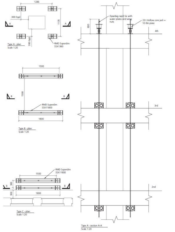
Figure 1. Load Testing Arrangements.
All tests follow the same basic set up; jacks are positioned on beams (generally sections on RMD super slim soldiers) which are tied to a number of floors below to achieve the required mass to jack against. The jacks can be propped from above instead of tied from below, but the props require large sections to resist buckling when compared to a 15mm diameter bar which is rated to 9t in tension. The specifics of each test is below:
Test Type A:
This is designed to test the capacity of the concrete columns. The test checks punching shear at the column faces in order to ensure that the excavator does not punch through the slab at these points. Set up shown in Figure 2.
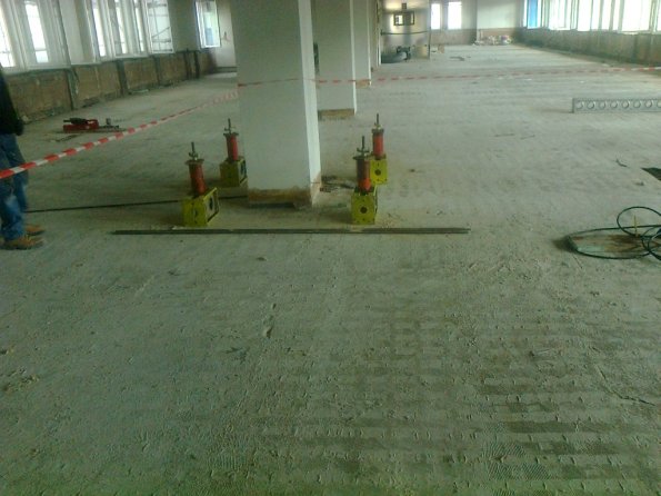
Figure 2. Test Type A.
Type B:
The Type B test is designed to test the capacity of the concrete slab and will take place at the point generating the largest moment and shear actions. The proposed testing will check flexural and shear strength in order to ensure the excavator does not fail the slab at these points.
Type C:
The Type C test is designed to test the capacity of the walls or edge columns. The proposed testing will check punching shear at the edge columns and the face of the wall in order to ensure that the excavator does not punch through the slab at these points.
Outcome
Generally option 1 and 2 are conducted, and unless a minimum of 8t machine (actually 9.6t with demolition equipment attached) is able to be used on the slab, load testing is requested. Load testing is time consuming, but it can generally be conducted during soft strip and has the potential of allowing a far larger machine to be used, saving much time in the process. When all three options have been used and the required capacity has not been achieved, the slab will be back-propped to a number of floors below to achieve the required capacity. Back-propping is time consuming and resource intense, so the fewer levels of back propping the better. As a matter of course, KG back-prop at least one level around all columns to mitigate punching shear.
Reflection
Load tests generally result in the floor having a capacity of circa 300% of the design value. Some of this accounted for by rational design, conservative assumptions in design and material strength, as stated earlier. I have identified the following additional reasons.
‘Non-structural’ screed
Most slabs have 50mm of screed on top. This is taken into account in the self-weight, but is neglected from structural calculations. In reality, screed does possess significant compressive strength. When the compressive region of the slab is on the top, which is usually the case, this screed increases the lever arm of the slab, increasing the capacity.
Ultimate limit state
Demolition engineering is not concerned with serviceability limit states, although there are exceptions, such as partial demolitions. Cracking in the tension zone is not a concern if the building is being demolished. This allows far greater loads to be applied whilst maintaining structural stability.
If anyone has any extra theories as to why structures are so much stronger than their design suggests then I would be interested to hear them.
