Archive
Batter… that’s something you put on fish right?
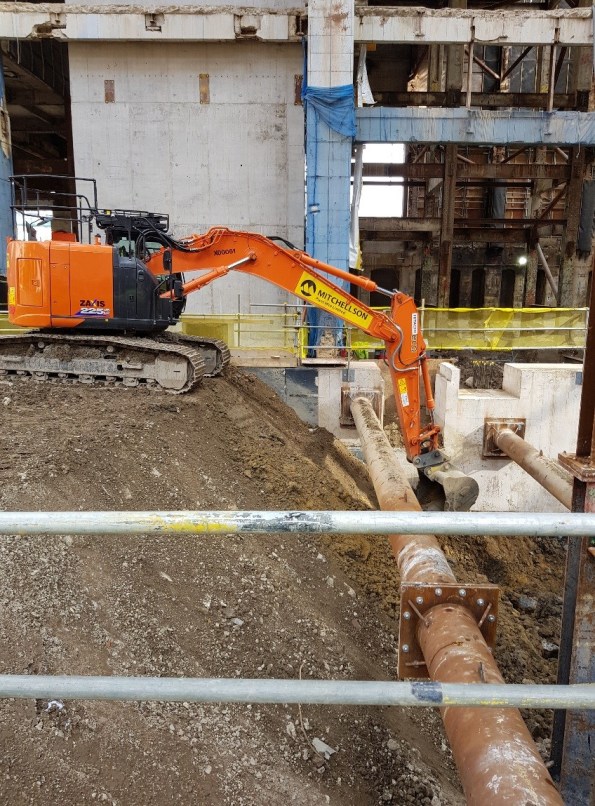
I’m working on Phase 2 of the Battersea Power Station Development Project (the actual power station bit). This post is related to Heath and safety on site. On the surface of it they appear incredibly H&S conscious, with a site flooded with orange jacketed traffic marshals and slinger-signallers and the logo “safety first, second nature” plastered everywhere. However, with a bit of digging below the surface (quite literally) they don’t seem to be quite as worried about the slightly less obvious but potentially incredibly dangerous situations. This lack of safety manifests itself in two ways; 1) constantly putting workers down deep excavations without any attempt at slope stabilization and 2) loading the top of steeply battered slopes. The second of these situations is the one I’ll go into detail on.
The situation shown below grabbed my attention on site because the slope batter looked to be at an angle that is too steep to support construction plant so close to the edge. I mentioned this to the supervisor and construction manager on site, who were not worried, believing that 45 degrees was an “ok” batter (I think that 45 deg is generous). Recalling that the thi dash/2 plus 45 rule goes out of the window when loaded, I was not sure about this, so checked it with some analysis on Geo5.
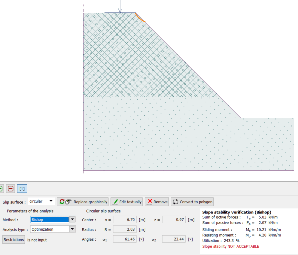
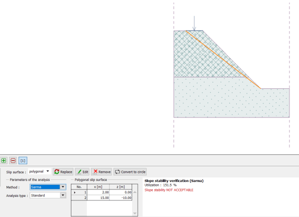
 Some quick calculations on Geo5 using the information obtained from the Ground Investigation Report show an unstable slope.
Load (mass 23000kg) = 226 kN
Modelled as a distributed load over the area of the excavator.
The ground profile is not certain, due to the possible presence of a scour feature. I have taken the case as being in the Short term, as the excavation is only to be at this angle for a couple of days. So the worst case is with granular made ground from 0 to -8, and scour infill from -8 to -15.
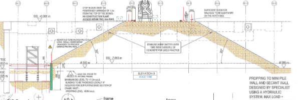
After some more digging (i’m sure this pun has been done 100 times before on this blog but it’s worth getting it in), I also found the Risk Assessment/ Method Statement, which states that the safe batter is 30 degrees, and that stop blocks should be positioned a minimum of 1.1 m from the edge. I informed my supervisor, who is also the senior project manager in charge of ground works, who said that he would look into it. They have since carried out a deeper excavation on a steeper slope elsewhere. 🙂
Time spent on resin is rarely wasted..
This blog is mainly aimed at my fellow phase 2 students and will probably appear obvious to the more experienced readers. However, I thought I would share a quick post about the amount of construction time that could be saved by challenging the detailing the design team annotate on drawings.
Firstly, as I have not yet blogged about my project, a quick introduction is required. I am working on the metro extension project in Melbourne, which is being undertaken as a joint venture by John Holland, Lendlease and Bouyges Construction under the contractor name Cross Yarra Partnership (CYP). In short, over the next 6 years the project will deliver two twin 9km tunnels and 5 new underground stations, with multiple entrances, within the Central Business District (CBD) and close suburbs (figures 1 and 2). The project is at the very beginning of construction and I am working within the CBD shafts team, delivering the 8 CBD station boxes that will allow access for underground mining operations and form the outer perimeter for the permanent station boxes (for the civils, think a more complex version of EX COFFERDAM). My current responsibilities are aligned to the design, procurement, installation and quality management of the temporary strut support system for each of the 8 CBD excavations, for which, the design and supply sub-contract has been awarded to Yongnam Steel (based in Singapore). Figure 3 shows a typical plan view of the strut layout.
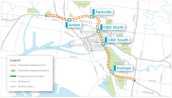 Figure 1 – Metro extension alignment
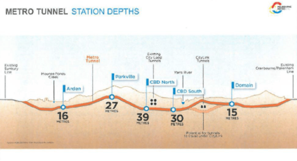 Figure 2 – Metro extension station depths
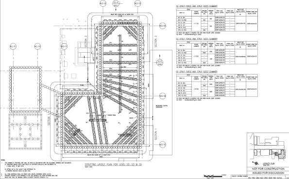 Figure 3 – Typical strut layout
So, into the meat of the issue. I was asked this week to investigate ways in which the installation timeline could be ‘rationalised’ to try and gain some time back on one of the excavations. Feedback given by the team working on site identified that the critical path for the installation of the waler and strut at each level was aligned to the amount of time the resin, for the bolts holding the waler support bracket, took to cure before loading (Min tcure). On the design drawings (figure 4) supplied by Yongnam, the detail stated that the epoxy adhesive should be Hilti HIT-RE500 or equivalent. As detailed on figure 4, this instruction is the same detail for each of the levels of struts, even though the waler and strut size at levels S6-S8 is much larger than the upper levels. The selection of the resin is based on the calculated shear and tension at the bracket location. The installation team suggested that this is most likely a standard detail on the upper levels, basically, to meet design timelines Yongnam will have designed for worst case shear and tension and then applied this across all levels. In terms of time, the minimum curing time for HIT RE-500 is 16hrs, which means the installation process is split across multiple 8 hr construction shifts. Whereas, for lower calculated shears and tensions, HILTI have other products such as HIT-HYH 200-R which cuts the tcure down to 2.5hrs, enabling more construction to take place within the 8hr shift and speeding up the overall installation process. There is also a combination of bolt size and resin selection that can be achieved to optimise tcure for each level of struts, dependent on the calculated shear and tension.
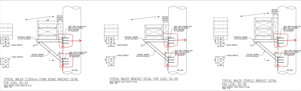 Figure 4 – Waler bracket detail
The RFI has been sent back to Yongnam to confirm the shear and tension at each plate location, so we can rationalise the selection of the bolt and the resin selection at each strut level. This detailing is something that I had never really considered could have such an impact on a project timeline, especially such a big influence on the critical path. This may be of some use to other phase 2’ers being asked to rationalise their own construction timelines. I will update the blog in the comments when I get the feedback from Yongnam and the final calculation of time saved is completed. Thoughts welcome on any other tips and tricks for cutting this time down?
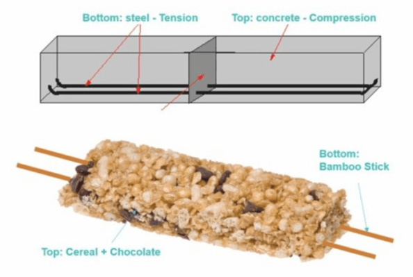
Chocrete…
For anyone thinking of conducting STEM activities there is a good idea/article about building with chocrete on the IStructE website, link below…
https://www.istructe.org/blog/2018/building-with-chocrete
West Gate Tunnel Project – Introduction
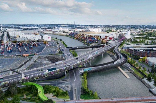
- Fig 1. WGTP Artist Impression
Intro
I have been on the West Gate Tunnel Project now for a little under a month. A $6.7 Billion dollar project, it has been designed to relieve pressure on the existing western road network as Melbourne continues to grow and infrastructure begins to feel the pinch.
A huge undertaking, the project has been awarded as a Fixed Price, Design and Construct (DC) JV between CPB and John Holland (CPBJH). CPB are currently the leading civil engineering company in Australia and JH also continue to feature as a major player.
Laydown
With an array of civil engineering works spread over ~14Km the project has been split into 3 discreet zones, West, Tunnel and East as can be seen in Fig. 2;
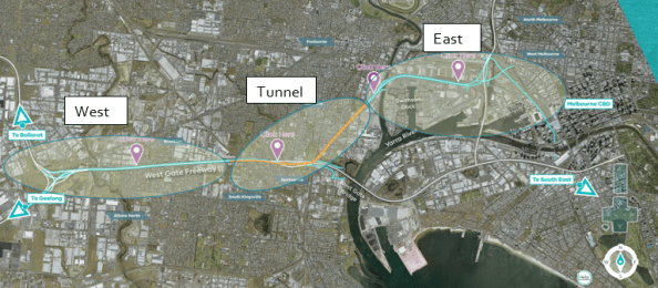
Fig 2. WGTP Zone Breakdown
Each zone loosely consists of the following works;
West – The West Zone incorporates the existing West Gate Freeway, which provides primary access to the city for all traffic from the west. Despite four lanes in either direction it is routinely subject to significant congestion. Accidents along this arterial route can all but cut off access to/from the West of the city. This accident rate and congestion along the freeway is exacerbated by traffic continuously weaving and merging along the route. As part of the project an additional two lanes will be added in either direction and “express lanes” segregated to improve the flow of traffic in/out of the city. Work in this zone is significantly complicated by restrictions imposed by the Victorian Government on lane closures throughout construction.
Tunnel – The Tunnel Zone, lying in the centre of the project bounds, is the first to see significant works. It will consist of twin tunnels of 2.8Km and 4Km respectively, which will be bored from North to South to draw traffic underground and away from residential areas (particularly HGVs). Work is currently underway in constructing the Northern Portal from where the two Tunnel Boring Machines (TBMs) will be launched. These are currently being manufactured in Germany and with a diameter of 15m, they will be the largest TBMs ever used in the Southern Hemisphere. Once here they will have to cope with some difficult ground conditions and the cutting head will often be cutting across a mix of different strata. Fig 3. shows a geological profile at the Northern Portal site. Behind the TBMs a mobile factory will place pre-cast concrete tunnel section to complete the structure.

Fig 3. Geological Profile @ Northern Portal

Fig 4. Geological Profile Key
East – The East Zone of the project will serve as a link from the Tunnel Zone to the Central Business District (CBD) and CityLink, the main arterial route leading North of the city and to the airport. It will consist of a bridge across the Maribyrnong River as well as extensive sections of elevated roadway linking into the heart of the city. Featuring in the latter stages of the programme, the complexity involved in the delivery of these works has been identified as a key risk to successful delivery of the project and a new package manager, recently employed on the Queensferry Crossing in Scotland, has been appointed to review the package in its entirety.
Additional to the construction zones, the project will also be running its own pre-cast yard, to produce the vast quantities of pre-cast elements require across the Tunnel Zone, as well as in the East Zone.
Role
I have now been appointed as a Project Engineer to the Northern Portal Team, who are responsible for the bottom up construction of the portal structure. At present we are focussed on delivery of the bare portal structure within which the TBMs will be built ready to begin their journey underground. This temporary/permanent structure will take the form of a secant piled “horseshoe” which incorporates fibre glass reinforced piles at the portal headwall to allow the TBMs to break through. Once excavated a base slab will be poured over numerous tension piles on which the TBM will be built. The ~40m wide box requires significant temporary propping during excavation and I am currently developing the scope of work for its placement and removal. Fig 5/6. details the general propping arrangement at roof level, while Fig 7. give a view of the section at the headwall.

Fig. 5 Cut and Cover Roof Plan
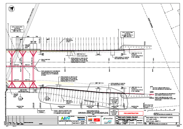
Fig 6. Cut and Cover Roof Plan 2
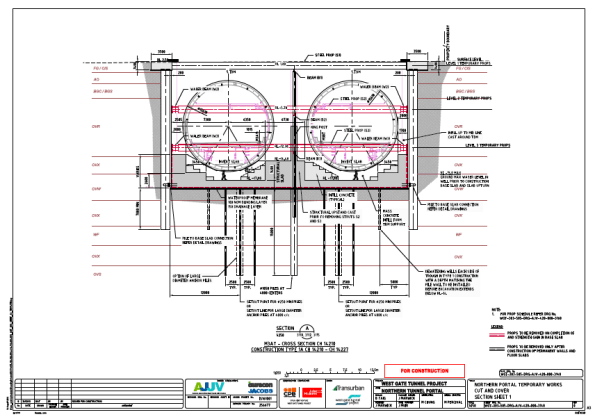
Fig 7. Northern Portal Section
Summary
There are certainly a lot of aspects to this project to capture my interest and I am sure in my relatively short time here I will be exposed to some of the challenges faced in delivering major civil infrastructure.
A couple of areas I might look at blogging about in the future or incorporating in AERs/TMRs are;
- Geotechnical Design/Challenges
- Approach to dealing with groundwater
- Diversity Employment targets
- Management structure on large scale infrastructure projects.
Cranfield high performance computers
A quick blog for those starting Phase 2 and thinking of thesis titles.
A less known about resource available to all PET students is the Cranfield high performance computers. This resource is invaluable if you are wanting to conduct any process heavy computational fluid dynamics (or FEA) using software packages such as ANSYS. Having just used this for my thesis I can highly recommend it, as without it, trying to execute on your own machine is a none starter! In addition, the student downloads that are available from ANSYS have inbuilt limitations on the size of problem you can execute.
If you are thinking about using this resource then more information can be found by searching on the Cranfield intranet for ‘accessing HPC’. You will then need to apply for the Crescent service, which is a dedicated teaching resource to MSc students. Once you have been granted access you are free to use the server.
A basic outline of the steps involved is to develop the model on your own machine, upload to your Cranfield storage, open on ANSYS remote desktop connection, finalise all aspects of the model, save as a .case file and exit, open Cranfield server and follow instructions to load a submission file. Once loaded into the server, there is no requirement to leave your laptop on as it will execute remotely and upload results to your online storage. Download and analyse.
There are other software packages available but ANSYS contains elements of and most aspects of both the C and E&M courses. If anyone think they are going to use it I can share the execution files that I used. They seemed to work ok ….
Gatwick Arrivals and Possible Projects
INTRO
My first week at Gatwick has been focused on the thorough induction training required by Gatwick Airport Limited (GAL) and getting time to talk with the people who will be able to get me set up on some projects.
Induction. GAL are not primarily an engineering firm but more an enduring operation focused on customer safety and maximising the efficiency and quantity of customer flow through the airport. So the training has been split between the mundane required safety training and the more interesting introduction to their corporate governance. I will neglect the former and talk a little on the latter especially on some of the training content. So far my key impression is that the civilian world seems a lot better at doing arrivals compared to the Regiments I have been posted into.
Projects. On the project side, I have had talks with and attended team meetings with Adam Jones who leads the Baggage Project, and with Gordon Winder who is lead for the Pier 6 Extension and associated projects. It is worth noting that in most cases GAL are on the client side of the project. I will talk a little about both projects in general as a back ground to future posts.
