Archive
West Gate Tunnel Project – Introduction
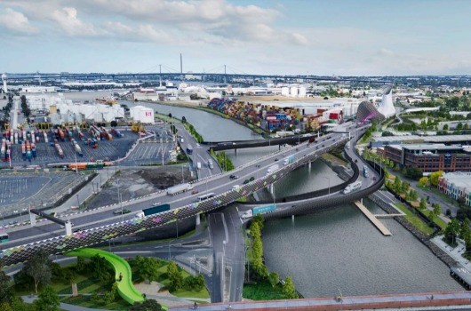
- Fig 1. WGTP Artist Impression
Intro
I have been on the West Gate Tunnel Project now for a little under a month. A $6.7 Billion dollar project, it has been designed to relieve pressure on the existing western road network as Melbourne continues to grow and infrastructure begins to feel the pinch.
A huge undertaking, the project has been awarded as a Fixed Price, Design and Construct (DC) JV between CPB and John Holland (CPBJH). CPB are currently the leading civil engineering company in Australia and JH also continue to feature as a major player.
Laydown
With an array of civil engineering works spread over ~14Km the project has been split into 3 discreet zones, West, Tunnel and East as can be seen in Fig. 2;
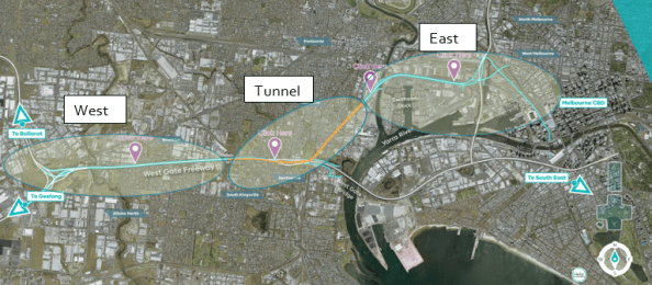
Fig 2. WGTP Zone Breakdown
Each zone loosely consists of the following works;
West – The West Zone incorporates the existing West Gate Freeway, which provides primary access to the city for all traffic from the west. Despite four lanes in either direction it is routinely subject to significant congestion. Accidents along this arterial route can all but cut off access to/from the West of the city. This accident rate and congestion along the freeway is exacerbated by traffic continuously weaving and merging along the route. As part of the project an additional two lanes will be added in either direction and “express lanes” segregated to improve the flow of traffic in/out of the city. Work in this zone is significantly complicated by restrictions imposed by the Victorian Government on lane closures throughout construction.
Tunnel – The Tunnel Zone, lying in the centre of the project bounds, is the first to see significant works. It will consist of twin tunnels of 2.8Km and 4Km respectively, which will be bored from North to South to draw traffic underground and away from residential areas (particularly HGVs). Work is currently underway in constructing the Northern Portal from where the two Tunnel Boring Machines (TBMs) will be launched. These are currently being manufactured in Germany and with a diameter of 15m, they will be the largest TBMs ever used in the Southern Hemisphere. Once here they will have to cope with some difficult ground conditions and the cutting head will often be cutting across a mix of different strata. Fig 3. shows a geological profile at the Northern Portal site. Behind the TBMs a mobile factory will place pre-cast concrete tunnel section to complete the structure.

Fig 3. Geological Profile @ Northern Portal

Fig 4. Geological Profile Key
East – The East Zone of the project will serve as a link from the Tunnel Zone to the Central Business District (CBD) and CityLink, the main arterial route leading North of the city and to the airport. It will consist of a bridge across the Maribyrnong River as well as extensive sections of elevated roadway linking into the heart of the city. Featuring in the latter stages of the programme, the complexity involved in the delivery of these works has been identified as a key risk to successful delivery of the project and a new package manager, recently employed on the Queensferry Crossing in Scotland, has been appointed to review the package in its entirety.
Additional to the construction zones, the project will also be running its own pre-cast yard, to produce the vast quantities of pre-cast elements require across the Tunnel Zone, as well as in the East Zone.
Role
I have now been appointed as a Project Engineer to the Northern Portal Team, who are responsible for the bottom up construction of the portal structure. At present we are focussed on delivery of the bare portal structure within which the TBMs will be built ready to begin their journey underground. This temporary/permanent structure will take the form of a secant piled “horseshoe” which incorporates fibre glass reinforced piles at the portal headwall to allow the TBMs to break through. Once excavated a base slab will be poured over numerous tension piles on which the TBM will be built. The ~40m wide box requires significant temporary propping during excavation and I am currently developing the scope of work for its placement and removal. Fig 5/6. details the general propping arrangement at roof level, while Fig 7. give a view of the section at the headwall.

Fig. 5 Cut and Cover Roof Plan
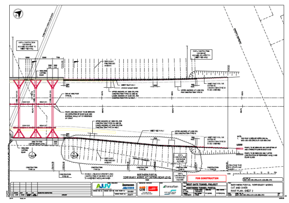
Fig 6. Cut and Cover Roof Plan 2
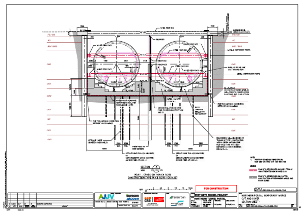
Fig 7. Northern Portal Section
Summary
There are certainly a lot of aspects to this project to capture my interest and I am sure in my relatively short time here I will be exposed to some of the challenges faced in delivering major civil infrastructure.
A couple of areas I might look at blogging about in the future or incorporating in AERs/TMRs are;
- Geotechnical Design/Challenges
- Approach to dealing with groundwater
- Diversity Employment targets
- Management structure on large scale infrastructure projects.
