Grouting a tree
This load-bearing architectural feature called a tree column is causing some problems.
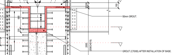
Grout will be poured into the void shown in red after the base has been installed. The designer/ Mace/ architect combo are worried that there will be voids in the grout.
Suggestions so far have been:
a) To measure the volume of grout poured in.
b) A mock-up has bee created to test construction and finish. They are proposing to cut this in section to check the grout.
The client weren’t satisfied with Option a and option b is ok but doesn’t check the actual tree columns.
My idea is to do option A and then use electrical imaging on both the mock-up and final tree-columns. Is this feasible, can electrical imaging be used for this type of thing? or are there other alternatives?

Can you stick a series of grout tubes in? Like filling a post-tensioned void, when grout flows out the top, you prove the cavity is full.
Ah, I see you just beat me to it!
Interesting. Is this a transition from concrete filled steel column sections to a steel frame? I’m struggling with the sheer studs on the sides of the column, which must be fixed to steel casing and there doesn’t appear to be any reinforcement of the concrete and so no starter bars etc. If my reading is right then the norm would be to use a grout tube to deliver grout to the lowest point beneath the upper column and it will flow up and level off. Same as grout filling pre-stress tendons, no worries, but you could try to measure the volume if you really wanted to. Is the designer an engineer or an architect? There appears to be little if any understanding of the technical in this. What actions are going to be applied to this “tree column” and why this strange detail?
Exactly as you said, it’s a connection between steel “branches” and concrete “trunk” (to use the architectural terminology). It was originally designed by an architect, But Buro Happold applied some engineering to it. Not sure if you clicked on the blue link on my post but that gives a fairly good representation of the design. Measuring the volume has been suggested, which most agree is the most sensible and suitable idea, but the client is so worried about these columns that they want to check^3.
Under a base like this you normally form a letter box form and post in CONBEX HF ( if the shimmed gap is down at 50mm) .Some insist on a vent holes in the base plate. Because of the unusual ‘U’ shape I can’t see why you would just tremie the grout in and then use vent holes. The more important thing is the non shrink ( hence Conbex) and the spec on the compressive stress required. This looks high. I looked and I think Conbex HF can get to 60-70 N/mm2 in 28 days
John,
Our methodology is essentially exactly as you have suggested (including the vent holes), however there are some worriers worrying that we could still get voids and not know about it, which is why I was thinking about some sort of electronic imaging. Not sure if this is possible with so many layers of different materials. We will essentially need to see voids that are within grout that is within a casing of steel that is wrapped in concrete.
With regards to the grout, the contractors are planning on using Masterflow 4800 which has proved successful elsewhere on site.