Archive
How to Splice up your life?
Just a quick post to see if anyone has a solution to the following issue which has arisen on my site, thought not in my immediate team.
BLUF: As I briefly mentioned in a previous post in order to avoid excessive wear on the TBM cutting head the designers have specified Glass Fibre Reinforced Plastic (GRP) reinforcement bars in the piles making up the head wall, through which the Tunnel Boring Machine (TBM) will eventually punch a hole. These have finally arrived following a series of delays but now there is some uncertainty on how the bars will be spliced together, as the team want to avoid the use of steel couplers.
Below is a picture of the GRP bar and the initially proposed method of using steel couplers;


My initial thoughts are that while I understand the use of GRP bars to avoid cutting through masses of steel I am surprised that relatively small gauge steel couplers will have much effect on the cutting head of a behemoth 15m dia TBM? Surely a monster of this size will just tear through the GRP bar and spit the couplers out whole at the other end?
If the couplers are likely to have a detrimental impact on the cutting teeth, then what might be a viable solution to forming a credible bond between sections of cage?
I welcome people thoughts and solutions.
UPDATE – 16/07/18
I don’t think my original description of the issue was very clear and what looks like a threaded end on the GRP bar in fig 2 might have been misleading. The bars were always going to be lapped (fig 1), but with U-bolts as seen below holding them together (I incorrectly called them couplers in the original post).

fig. 3 – U-bolt
Although these appear quite insignificant, the TBM guys have said they don’t want any steel, including these, in the piles when they cut through the head wall.
A number of possible solutions were investigated including cable ties as was suggested by Jim in the comments. However, these were deemed insufficient as the lapped connections will need to support the weight of a lower cage during installation.
Each cage is made up of two cages of around 15m in length. in the worst case loading the weight of the lower cage, 1200Kg is supported over 4 spliced connections as shown in the fig 4 below;

fig 4 – cage cross section
The solution that was put forward and adopted was to drill and fix 7 GRP pins through both GRP bars at each of the splice locations as outlined in fig 5.
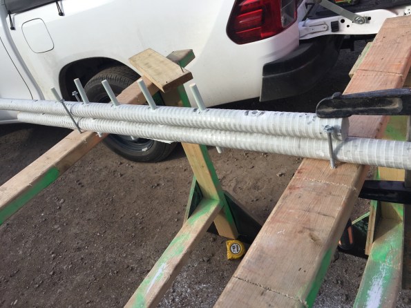
fig 5 – proposed solution
In order to adopt this as a solution, the connection had to put forward for testing to check that the strength of the connection was sufficient. The test load was based on the following;
- 1200Kg/4 splices -> 300kg per splice -> design load = 3000N
- Load test to 3000N and hold for 5 min
- Load test to 7500N (2.5 x design load) and hold for 5 min
- load test splice to failure (hopefully achieving 5 x design load, 15000N)
the image below shows the testing rig that was adopted by the lab;
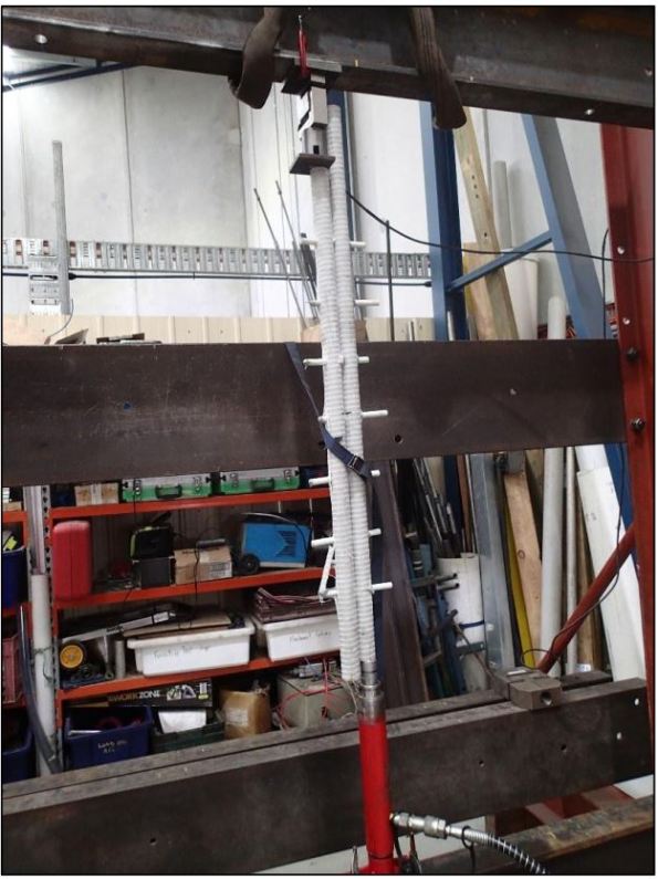
The test was repeated three time on the test pieces and yielded positive results with each test reaching 1500Kg with no defects, defections or cracking observed. This has now been adopted as the preferred solution.
They keep slipping up
A really juicy one here on concrete for the E&M’ers to get their teeth stuck into.
Here is something to watch out for if anyone is involved in slipforming.
-
- The four shear cores in my area at Battersea are being built using slipforms. The main benefit of this method is that it can be constructed very quickly (if carried out by a competent contractor with adequate round-the-clock quality assurance).
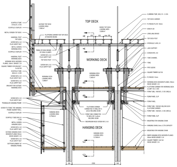
- Quick recap on Slipform: Shuttering (the formwork) is attached to yolks, which are held up by climbing tube. The slipform rig is held up entirely by the climbing tubes which run to the base of the slipformed wall, and the jacks are almost continuously lifting the slipform rig. The concrete that is exposed below the shuttering only needs to support it’s own weight, which is continuously checked as the slipform is lifted.
- The axial force produced by the jacks must overcome the friction between the shuttering and the concrete to allow the shuttering to move up. However, if the shear force due to friction between concrete and the shuttering overcomes the shear strength of concrete then the concrete can fail at the surface, resulting in poor finish. If the concrete has cured and the shear force overcomes the tensile capacity of the concrete then whole sections of wall can be dragged upwards. This happened on one of the cores in Battersea, resulting in large tear-outs and long delays.
- Sub-contractor’s reasons: The high strength C75/85 concrete that was used in this particular section of wall was going off too quickly, resulting in it adhering to the shuttering. A possible but flaky argument trying to transfer the blame to the concrete mixers.
- Weapon fires, weapon fires, weapon stops… The concrete was repaired using traditional formwork on the hanging deck, and after 8 days of repairs slipforming continued as normal… for a few days until the same thing happened again in an area where the normal C50/60 concrete was being used.
- What was the reason for failure? Slipforming is supposed to be a continuous process, so that the concrete is given time to harden in order to support it’s own weight, but not given too much time because it can adhere to the shuttering. Also, this means that there will not be weak ‘construction’ joints with the concrete below which will give the concrete poor tensile strength.
- First incident (photos below): There had been a long pause in order to fix some large steel embedment plates before the concrete was poured. The concrete was poured on the night shift, where as it later emerged, the subcontractor had no QA managers working and an inexperienced concrete foreman/supervisor. It is possible that the high strength concrete was going off quicker, but this should have been anticipated and either arranged to be poured quicker or designed with admixtures to slow the curing process. An operative on site also let slip that the concrete looked as if it had gone off when it was poured.


- Second incident: (photo below) After the first incident, the exposed shuttering was cleaned, however the shuttering overlaps the concrete at the bottom by about 0.4 m to allow a good seal when pouring concrete. It is likely that in this area there is a film of concrete that has stuck to the shuttering, which makes it much easier for fresh concrete to bind to the shuttering. The failure occurred after a very hot day, which is likely to have compounded the problem due to increased speed of curing.

- After some investigation it seems as if the most likely problem is that the sub-contractor has not been managing their logistics well, allowing concrete to stand on site, or having large quantities turn up at once causing queuing. It seems as if there were two failings here; in logistics managemnt and in Quality Assurance. A real Sliphopopotamus.
Construction micro-organisms: Anthrax from contaminated land and buildings
I have just had to do this weeks “Safety Moment” presentation for my Programme Office. For this I decided to do an unusual risk but one that is present on my site and could be present when we as the Army operate overseas.
BLUF: A very small likelihood but given a lot of attention due to the possible consequences.
- What is Anthrax. Anthrax is primarily a disease of herbivores (plant eating animals). Humans contract it as a result of contact with infected animals or animal products. In humans, the disease takes one of three forms, depending on the route of infection. Cutaneous anthrax, which accounts for more than 95% of cases world-wide, results from infection through breaks in the skin; intestinal anthrax results from ingestion of spores, usually in infected meat; and pulmonary anthrax results from inhalation of spores.
- Anthrax in the UK. The UK has an exceptionally low rate of anthrax, and nearly all cases since 1981 have been associated with imported material. Of the 19 cases reported, in England & Wales between 1981 and 2009, all but one were cutaneous.
- Cutaneous Anthrax Explained. Cutaneous anthrax usually occurs through contamination of a cut or abrasion, although in some countries biting flies may also transmit the disease. The first sign of an anthrax infection is a small painless inflamed swelling like a pimple or boil.
- Pulmonary Anthrax Explained. In pulmonary anthrax, inhaled spores multiply to cause disease that affects the entire body instead of a specific organ. This is an occupational disease encountered in industries in which the workers are exposed to high levels of spores in dust. Pulmonary anthrax, although exceedingly rare, are both more dangerous than the cutaneous form because they are usually identified too late for treatment to be effective.
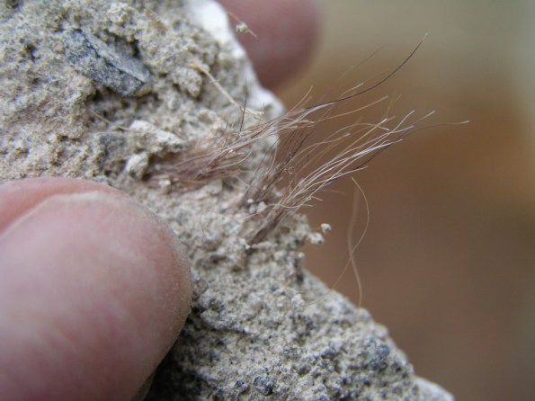
- Anthrax in construction and demolition. Animal hair has been used as an ingredient in internal plasters for centuries. The best hair was obtained fresh from the tanners yard. Controls for the prevention of anthrax have existed since 1919; however, there is no guarantee that hair in plaster used before 1900 was not contaminated in the construction industry. In addition controls were not greatly enforced until after WWII.
- Risk. In reality, the risk of developing an anthrax relating infection is low so long as suitable and sufficient risk assessments and management plans are adhered to.
- Mitigation Methods.
- Basic.
- Cover cuts and abrasions
- Keep hands clean
- Wear suitable PPE (e.g. disposable gloves, overalls)
- Prohibit smoking and consumption of food and drink
- Ensure plaster is handled and disposed of in accordance with local and statutory controls and dust generation is minimised.
- Personnel informed of the risk and the risk management system.
- Respiratory Protective Equipment (RPE) – wear RPE if removing old plaster containing animal hair. Choose RPE with an assigned protection factor of 20 (eg FFP3 disposable mask or half mask with P3 filter). For longer duration work consider powered RPE with the same protection (eg TH2 powered hood / helmet).
- Basic.
- Military Construction. The Royal Engineers need to recognise that in the future operating environment a large amount of construction will be refurbishment of existing buildings on brownfield sites. Contamination of these sites is to be expected and the only tools in the military’s arsenal to deal with this is CBRN equipment and TTPs. The Royal Engineers should consider gaining the skills necessary to deal with its own contaminated sites overseas whether it be Anthrax, Industrial Chemicals or Asbestos.
Future Phase 3 (Civil) placement in London
Hi everyone, not a technical blog, just passing on contact details of my Phase 3 in case anybody wants to go there next year.
I have been working for Wentworth House Partnership (WHP), who are part of the Keltbray Group. Keltbray are a specialist contractor, traditionally in demolition, but have expanded into piling, asbestos removal and rail amongst other things. They have recently set up a structures business (concrete framing) in its own right, and have just won the contract to build Battersea Phase 3A.
WHP are the design consultancy for Keltbray, but do about 25% of their work for external companies. Most of the work is for temporary works, which means fast paced designs and a very varied experience. I cannot say if this is better or worse than a permanent works design office as I’ve not worked in one, but it has suited me. More hand calcs, less importance put on things being used to 100% of their capacity, as long as it works and is 80%+ efficient it is usually good enough.
I have designed in steel, timber, concrete and lots of design work using scaffolding and other off-the-shelf solutions. Some geo too; there is a geo ‘department’ (4 guys) but I have only really dipped my toes into the water there and done the simple analysis. All in there about 45 engineers and technicians in the office.
The three directors are all Fellows of the ICE and IStructE, and two are active ICE reviewers. They know what you need to pass CPR, and are a really good source of advice. They arrange weekly CPD in house over a free lunch and at any one time probably have about 5 or 6 of their own staff going through the Chartership process.
Stuart Marchand (the managing director of WHP) was a founding member of the temporary works forum and a previous chairman. Tim Lohmann (another director at WHP) is the current chairman, and the final director (Stuart Vaughan) probably will be chairman in the future. My point is that WHP is a very good place to learn about temporary works, which I think share many characteristics to a lot of military engineering solutions.
The office is in Esher, so really handy if you live in The Keep. If not it is a 24 minute train ride from Vauxhall. The full address is: Wentworth House Partnership St Andrew’s House Portsmouth Road Esher KT10 9TA.
If you’re interested, email the directors and mention the PET Course, they have hosted myself and Fred Kiddie before me so they know what the course is about.
director@wentworth-house.co.uk
