Archive
How to Splice up your life?
Just a quick post to see if anyone has a solution to the following issue which has arisen on my site, thought not in my immediate team.
BLUF: As I briefly mentioned in a previous post in order to avoid excessive wear on the TBM cutting head the designers have specified Glass Fibre Reinforced Plastic (GRP) reinforcement bars in the piles making up the head wall, through which the Tunnel Boring Machine (TBM) will eventually punch a hole. These have finally arrived following a series of delays but now there is some uncertainty on how the bars will be spliced together, as the team want to avoid the use of steel couplers.
Below is a picture of the GRP bar and the initially proposed method of using steel couplers;


My initial thoughts are that while I understand the use of GRP bars to avoid cutting through masses of steel I am surprised that relatively small gauge steel couplers will have much effect on the cutting head of a behemoth 15m dia TBM? Surely a monster of this size will just tear through the GRP bar and spit the couplers out whole at the other end?
If the couplers are likely to have a detrimental impact on the cutting teeth, then what might be a viable solution to forming a credible bond between sections of cage?
I welcome people thoughts and solutions.
UPDATE – 16/07/18
I don’t think my original description of the issue was very clear and what looks like a threaded end on the GRP bar in fig 2 might have been misleading. The bars were always going to be lapped (fig 1), but with U-bolts as seen below holding them together (I incorrectly called them couplers in the original post).
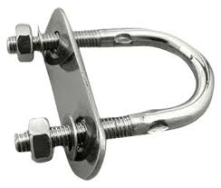
fig. 3 – U-bolt
Although these appear quite insignificant, the TBM guys have said they don’t want any steel, including these, in the piles when they cut through the head wall.
A number of possible solutions were investigated including cable ties as was suggested by Jim in the comments. However, these were deemed insufficient as the lapped connections will need to support the weight of a lower cage during installation.
Each cage is made up of two cages of around 15m in length. in the worst case loading the weight of the lower cage, 1200Kg is supported over 4 spliced connections as shown in the fig 4 below;

fig 4 – cage cross section
The solution that was put forward and adopted was to drill and fix 7 GRP pins through both GRP bars at each of the splice locations as outlined in fig 5.
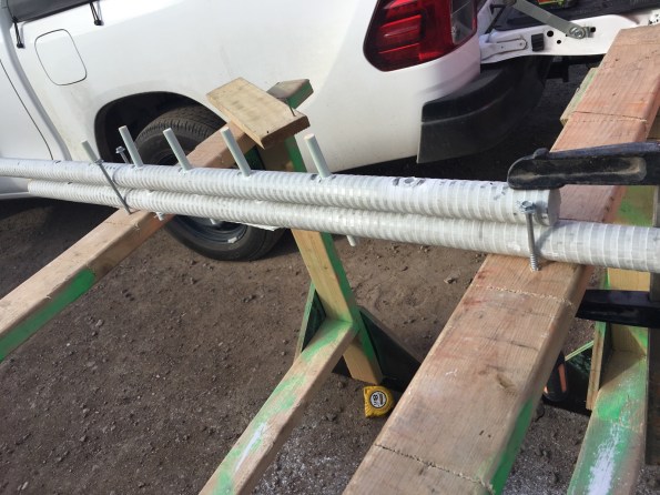
fig 5 – proposed solution
In order to adopt this as a solution, the connection had to put forward for testing to check that the strength of the connection was sufficient. The test load was based on the following;
- 1200Kg/4 splices -> 300kg per splice -> design load = 3000N
- Load test to 3000N and hold for 5 min
- Load test to 7500N (2.5 x design load) and hold for 5 min
- load test splice to failure (hopefully achieving 5 x design load, 15000N)
the image below shows the testing rig that was adopted by the lab;
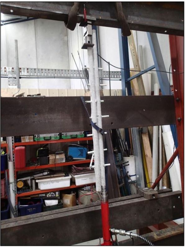
The test was repeated three time on the test pieces and yielded positive results with each test reaching 1500Kg with no defects, defections or cracking observed. This has now been adopted as the preferred solution.
