Archive
Controlling deflections in metal decks

Fig. 1 Jaguar Land Rover – Noise Vibration & Harshness Project Roof Aug 2018
Steel and concrete interfaces on my project are causing us to ‘wave’ goodbye to the specified tolerances.
For an element of multi-story steel frame, we are forming composite floor slabs from metal decking and in-situ concrete. This seemingly tried and tested method benefits from the speed of frame construction and a reduction in material costs due to combined geometric performance. And yet, even with an experienced design team and contractor, the finished levels of our slabs wave up and down by ~40mm.

Fig. 1a Heat map underside of slab defelctions
A quick google search generates lots of information and warnings relating to level tolerances for composite metal deck slabs but the outcomes we have observed seem to surprise the project team.
Is anyone else using metal decking or aware ways to overcome problems with its use?
1. Tolerances
A regular 6m x 7m grid of columns supports a typical arrangement of primary and secondary beams.
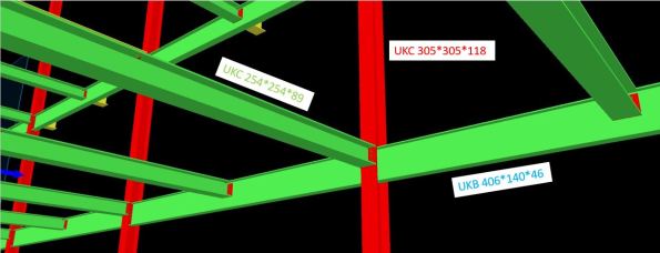
Fig. 2 Screen grab of model with slab removed
Table 1 – Steel Frame Elements
| Element | Size |
| Column | UKC305*305*118 |
| Primary Beam | UKB406*140*46 |
| Secondary Beam | UKC254*254*89 |
| Metal Deck | ComFlor 51+ |
The designer produced a tolerance specification, in which they confirmed deflections should not exceed the lesser of span/180 or 20mm (in accordance with UK National Annex to BS EN 1994-1-1 and BS5950-4).
In our frame; 7000 / 180 = 38.8mm > 20mm therefore max δ = 20mm.
As built surveys confirmed that the secondary beams (UKC254) were consistently deflecting ~20mm under construction loads only. This was also true of the primary beams (UKB406).
The greatest deflection is highlighted by the sketch in Fig. 3 and occurs when the secondary is connected to the primary at mid-span. The 20mm tolerance has already been used up and the subsequent deflection in the secondary means the combined deflection at mid-point of the slab is ~40mm.
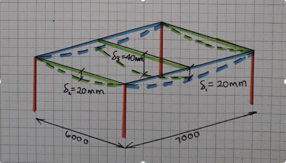
Fig. 3 Steel frame bay deflections
2. Method
The concrete pour on Level 1 was poured to a level. An inexperienced graduate engineer was convinced by a construction manager that this was the correct methodology. All drawings indicated that slabs on metal decking should be poured to a thickness to prevent ponding of concrete.
As more concrete was poured to achieve the correct level, the deflection increased under the additional self-weight loading. This cycle continued and resulted in a slab 40mm thicker than design at mid-span.
We felt this error in methodology was the root cause of the excessive deflection. For Level 2, particular attention was applied to ensure the slab was poured to a thickness and yet similar deflections were observed (Fig. 4).
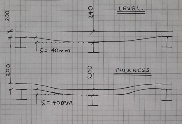
Fig. 4 Slab profiles
3. Future options to limit deflection
This had led me to believe that the sections have been under sized in the design. The slab on Level 2 is due to be a plant room and has gullies positioned adjacent to columns – if any of the plant leaks, water will not run uphill on our wavy slab!

Fig. 5 Finished level variation in slab pour to thickness
In a report by the ASCE[1], four options to reduce deflection in composite metal decks are offered;
- Increase section sizes
- Pre-camber members
- Place additional concrete
- Back propping
Given that our frame is already built, the only option I think we have is to install temporary works to back prop future slab pours.
I welcome any other suggestions…
Will we also need to increase the reinforcement in the slab?
Should we allow for more deflection once variable loads are applied?
______________________________________________________________________________________
Updated to show more recent as-built heat map of finished level of slab.
Majority of LHS was poured to a level with clear results +/-9mm.
RHS and bottom left all poured to thickness with -40mm under secondary beams.
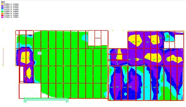
Fig. 6 As-built finished levels
[1] https://www.concreteconstruction.net/_view-object?id=00000153-8c44-dbf3-a177-9c7d96b40000
Loads of Temporary Steel
Introduction:
This seems like a relatively unique engineering feat so thought worth a quick blog to share how I think it works and highlight an issue which will soon need addressing.
The original Shell House structure is being renovated. The clock tower and three sides of the facade stay, everything else goes. Also, an additional 4 storeys are excavated prior to building back up.
Image 1. Original Shell house structure
Retention works prior to demolition:
- Plunge columns
- Crane base
- Stability core
- Perimeter transfer structure
- Clocktower transfer and support elements
Retention works during Demolition:
- Façade support braces inserted as demolition progresses
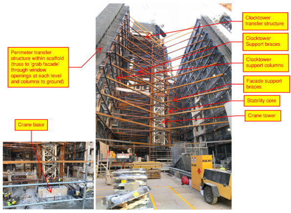
Image 2. Facade retention system as at 24 Aug 18
How I think it works:
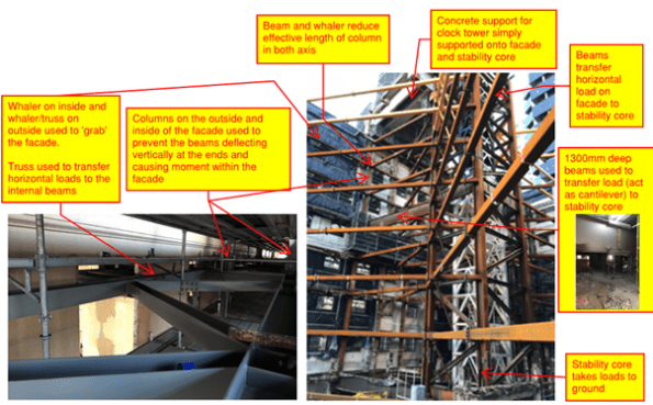

Image 3. How I think it works
Retention works during excavation (soon to commence):

Image 4. Excavation procedure
Issue:
Plunge columns are up to 40mm out of plumb – what are the risks, how can they be mitigated?
I hope to answer these questions in my next TMR so any comments very welcome
Concrete Quality: How Bad Can It Get Before Structural Compromise?
Hello all,
Just a quick one to spark some debate and follows on from Ed’s the other day. I have been involved with the vertical elements of my project site which include columns and outrigger core walls. The pours have been going well but on opening the forms up today a number of elements have had issues. Multiplex have referred these issues to the consulting engineers and are waiting on their response for the required remedial action or acceptance as they see fit. Some of the elements where poured on different days using a mixture of kibbling and pumping. All are 80mpa which generally is being reached well before the 28 day mark with the columns feelably hot. The mix is designed to be self compacting with no requirement for vibration but the supplier has been having issues with producing consistently accurate mixes. These elements are on level 7 of 82.
Column 1 – Evidence of very small honeycombing and cold pour joints
I would suggest that no rectification is required for this column. Your thoughts?
Column 6 – Evidence of small honeycombing and cold pour joints
Again I would suggest that no rectification is required for this column. Your thoughts?
Column 7 – Evidence of cold pour joints and large scale honeycombing which is exposing reinforcement.
My feeling on this one is that rectification will be required. I think that as a minimum they will ask for the concrete to patched to cover over the steel work but that more extreme remediation could well be asked for.
Column 10 & Outrigger Core Wall 8 – Evidence of small honeycombing and cold pour joints isolated to a single batch of concrete. This was kibbled and you can clearly see the flow of concrete away from the column, which was the insertion point, into the rest of the wall.
As before I would suggest that no rectification is required for this column. Your thoughts?
Multiplex should be getting the consultants response shortly so I will update the post with this detail once received and you will be able to compare your thoughts to that of what actually happened.
National Trust vs Apple; Who will win?
This isn’t a technical blog, but a quick update to share experience of a heritage issue we are currently working through in my construction precinct. One of our three station entrances is to be constructed in an area known as Federation Square within the Melbourne Central Business District (images 1 & 2). Construction work was due to start on 2 September 2018, however, we have just been served with a 60day interim heritage protection notice for Federation Square. The protection notice is the result of an application by the National Trust to the Heritage Victoria Register, in response to the Victorian Government approving plans for the construction of the new flagship Apple store at Federation Square (image 3). The development of the Apple store requires the demolition and relocation of the Yarra Building which currently houses an indigenous people museum and arts centre (image 4). Federation Square was developed in 2002 as a central meeting place for Melburnians where the culture and heritage of the City could be displayed and public events could be held. The previous Melbourne City Square was sold for re-development. If Federation Square is granted heritage status then all current and future construction works, including our station entrance, will require to go through a lengthy permit process to ensure that the design can meet the criteria for constructing in a heritage area. The project is unsure which way the decision will go. There is currently no precedent for heritage status being awarded to such a young structure (16 years). However, the Victorian Heritage Act 2006, does not specifically define how old a place must be and the Heritage Victoria Register will consider any nomination put forward. The issuing of the interim protection notice has initiated talks with our Client (Rail Projects Victoria) to identify which clauses of the contract can be triggered now and what are the time and cost implications if the heritage status is granted. I will keep you updated with how this one turns out.
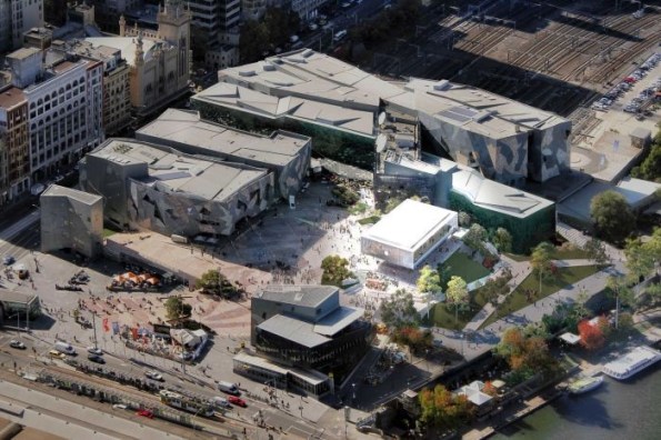
Image 1 – Aerial view of Federation Square. Proposed new station entrance bottom left and proposed Apple store center right.
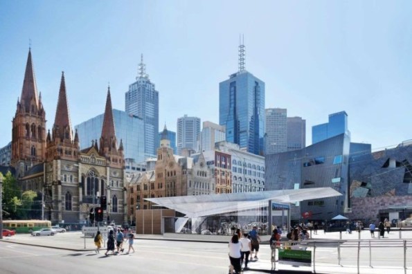
Image 2 – Proposed new Metro Tunnel Entrance at Federation Square
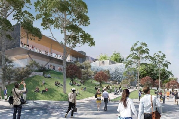
Image 3 – Proposed new Apple store. View from Yarra River.

Image 4 – Current street view of Federation Square. Buildings on right of picture to be demolished for Apple store construction.
