Archive
Controlling deflections in metal decks

Fig. 1 Jaguar Land Rover – Noise Vibration & Harshness Project Roof Aug 2018
Steel and concrete interfaces on my project are causing us to ‘wave’ goodbye to the specified tolerances.
For an element of multi-story steel frame, we are forming composite floor slabs from metal decking and in-situ concrete. This seemingly tried and tested method benefits from the speed of frame construction and a reduction in material costs due to combined geometric performance. And yet, even with an experienced design team and contractor, the finished levels of our slabs wave up and down by ~40mm.

Fig. 1a Heat map underside of slab defelctions
A quick google search generates lots of information and warnings relating to level tolerances for composite metal deck slabs but the outcomes we have observed seem to surprise the project team.
Is anyone else using metal decking or aware ways to overcome problems with its use?
1. Tolerances
A regular 6m x 7m grid of columns supports a typical arrangement of primary and secondary beams.
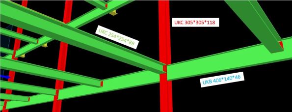
Fig. 2 Screen grab of model with slab removed
Table 1 – Steel Frame Elements
| Element | Size |
| Column | UKC305*305*118 |
| Primary Beam | UKB406*140*46 |
| Secondary Beam | UKC254*254*89 |
| Metal Deck | ComFlor 51+ |
The designer produced a tolerance specification, in which they confirmed deflections should not exceed the lesser of span/180 or 20mm (in accordance with UK National Annex to BS EN 1994-1-1 and BS5950-4).
In our frame; 7000 / 180 = 38.8mm > 20mm therefore max δ = 20mm.
As built surveys confirmed that the secondary beams (UKC254) were consistently deflecting ~20mm under construction loads only. This was also true of the primary beams (UKB406).
The greatest deflection is highlighted by the sketch in Fig. 3 and occurs when the secondary is connected to the primary at mid-span. The 20mm tolerance has already been used up and the subsequent deflection in the secondary means the combined deflection at mid-point of the slab is ~40mm.
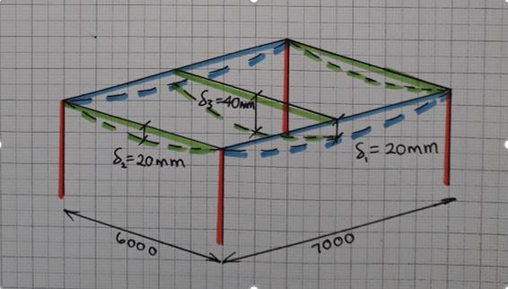
Fig. 3 Steel frame bay deflections
2. Method
The concrete pour on Level 1 was poured to a level. An inexperienced graduate engineer was convinced by a construction manager that this was the correct methodology. All drawings indicated that slabs on metal decking should be poured to a thickness to prevent ponding of concrete.
As more concrete was poured to achieve the correct level, the deflection increased under the additional self-weight loading. This cycle continued and resulted in a slab 40mm thicker than design at mid-span.
We felt this error in methodology was the root cause of the excessive deflection. For Level 2, particular attention was applied to ensure the slab was poured to a thickness and yet similar deflections were observed (Fig. 4).
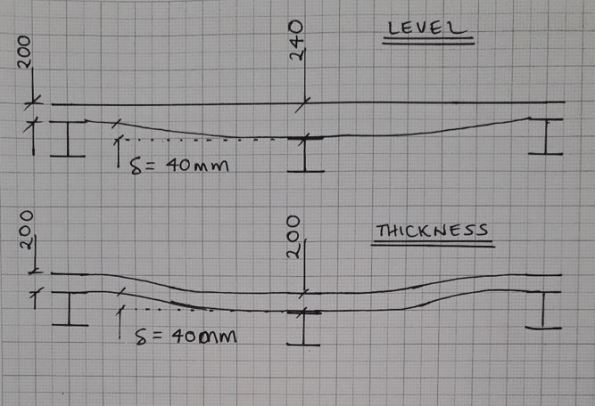
Fig. 4 Slab profiles
3. Future options to limit deflection
This had led me to believe that the sections have been under sized in the design. The slab on Level 2 is due to be a plant room and has gullies positioned adjacent to columns – if any of the plant leaks, water will not run uphill on our wavy slab!

Fig. 5 Finished level variation in slab pour to thickness
In a report by the ASCE[1], four options to reduce deflection in composite metal decks are offered;
- Increase section sizes
- Pre-camber members
- Place additional concrete
- Back propping
Given that our frame is already built, the only option I think we have is to install temporary works to back prop future slab pours.
I welcome any other suggestions…
Will we also need to increase the reinforcement in the slab?
Should we allow for more deflection once variable loads are applied?
______________________________________________________________________________________
Updated to show more recent as-built heat map of finished level of slab.
Majority of LHS was poured to a level with clear results +/-9mm.
RHS and bottom left all poured to thickness with -40mm under secondary beams.
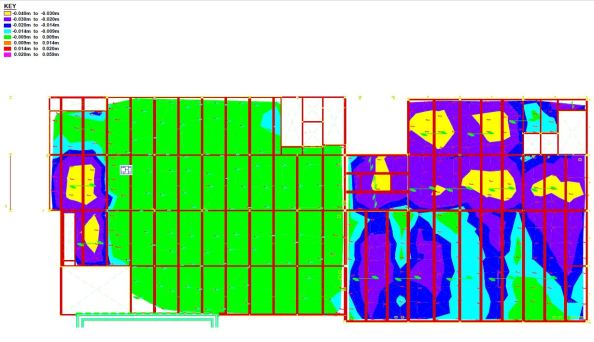
Fig. 6 As-built finished levels
[1] https://www.concreteconstruction.net/_view-object?id=00000153-8c44-dbf3-a177-9c7d96b40000
