Controlling deflections in metal decks

Fig. 1 Jaguar Land Rover – Noise Vibration & Harshness Project Roof Aug 2018
Steel and concrete interfaces on my project are causing us to ‘wave’ goodbye to the specified tolerances.
For an element of multi-story steel frame, we are forming composite floor slabs from metal decking and in-situ concrete. This seemingly tried and tested method benefits from the speed of frame construction and a reduction in material costs due to combined geometric performance. And yet, even with an experienced design team and contractor, the finished levels of our slabs wave up and down by ~40mm.

Fig. 1a Heat map underside of slab defelctions
A quick google search generates lots of information and warnings relating to level tolerances for composite metal deck slabs but the outcomes we have observed seem to surprise the project team.
Is anyone else using metal decking or aware ways to overcome problems with its use?
1. Tolerances
A regular 6m x 7m grid of columns supports a typical arrangement of primary and secondary beams.
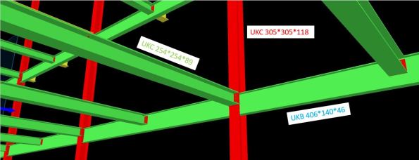
Fig. 2 Screen grab of model with slab removed
Table 1 – Steel Frame Elements
| Element | Size |
| Column | UKC305*305*118 |
| Primary Beam | UKB406*140*46 |
| Secondary Beam | UKC254*254*89 |
| Metal Deck | ComFlor 51+ |
The designer produced a tolerance specification, in which they confirmed deflections should not exceed the lesser of span/180 or 20mm (in accordance with UK National Annex to BS EN 1994-1-1 and BS5950-4).
In our frame; 7000 / 180 = 38.8mm > 20mm therefore max δ = 20mm.
As built surveys confirmed that the secondary beams (UKC254) were consistently deflecting ~20mm under construction loads only. This was also true of the primary beams (UKB406).
The greatest deflection is highlighted by the sketch in Fig. 3 and occurs when the secondary is connected to the primary at mid-span. The 20mm tolerance has already been used up and the subsequent deflection in the secondary means the combined deflection at mid-point of the slab is ~40mm.
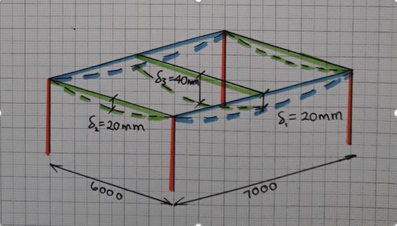
Fig. 3 Steel frame bay deflections
2. Method
The concrete pour on Level 1 was poured to a level. An inexperienced graduate engineer was convinced by a construction manager that this was the correct methodology. All drawings indicated that slabs on metal decking should be poured to a thickness to prevent ponding of concrete.
As more concrete was poured to achieve the correct level, the deflection increased under the additional self-weight loading. This cycle continued and resulted in a slab 40mm thicker than design at mid-span.
We felt this error in methodology was the root cause of the excessive deflection. For Level 2, particular attention was applied to ensure the slab was poured to a thickness and yet similar deflections were observed (Fig. 4).
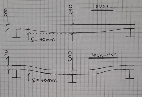
Fig. 4 Slab profiles
3. Future options to limit deflection
This had led me to believe that the sections have been under sized in the design. The slab on Level 2 is due to be a plant room and has gullies positioned adjacent to columns – if any of the plant leaks, water will not run uphill on our wavy slab!

Fig. 5 Finished level variation in slab pour to thickness
In a report by the ASCE[1], four options to reduce deflection in composite metal decks are offered;
- Increase section sizes
- Pre-camber members
- Place additional concrete
- Back propping
Given that our frame is already built, the only option I think we have is to install temporary works to back prop future slab pours.
I welcome any other suggestions…
Will we also need to increase the reinforcement in the slab?
Should we allow for more deflection once variable loads are applied?
______________________________________________________________________________________
Updated to show more recent as-built heat map of finished level of slab.
Majority of LHS was poured to a level with clear results +/-9mm.
RHS and bottom left all poured to thickness with -40mm under secondary beams.
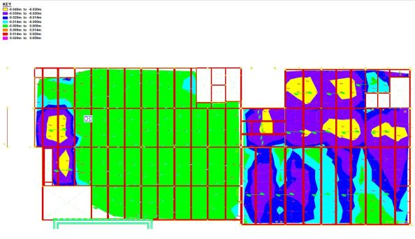
Fig. 6 As-built finished levels
[1] https://www.concreteconstruction.net/_view-object?id=00000153-8c44-dbf3-a177-9c7d96b40000

There appears to be a a circular argument going on in the design stage here
IF you are able to limit deflection ( in the temporary stage) to a 1/10 of the slab depth, then be EN 1994-1-1 allows you NOT to add an additional ponding load ( normally added at 0.7 deflection) But just saying that the limit should be 20mm on a 200mm slab doesn’t achieve this- the design does!
I put a compo slab in at a limiting span last year and the only thing that you can do is
a) temporary in span deck propping
b) Using Lytag concrete
On the latter I am surprised that most of the guidance forgets to mention this You can get down to about 18 kN/m3 That will take a third off the temporary state deflections
Although he manufacturers’ claim that the work ability is the same I found that you have to control placement closely. I was using it at very high strength though
On the issue of controlling it to level. In theory, of course, this is not possible. What you mean is controlling it to a level which allows for the system deformation
There is a BSCA Spec for compo flooring. In the area of deformation limit it just reels out the BS 8294-2 ( screeds) liits
There is a telling phrase though. Something like ‘ if the floor level is critical the frame designer should limit frame deflection to 10mm – I wish!
What it does say is that it is not something a novice should supervise.
Thanks for the steer John.
I’ve looked into the lightweight concrete and found this data sheet gives a good overview;
Click to access COL897260.pdf
In our plant room there is talk of moving the gullies to mid span in the slab or creating a fall in screed (more load, more deflection… I’m not convinced).
Hi mate,
I assume everything is already procured so surely back propping is the answer as will stop them having to add additional concrete to get the level – assuming this reduces the load enough for the beams to pass SLS, will there not still be ponding issues when the props are removed? Suppose this is generic for all slabs which are subject to the weather (or plant leaks) as they will all deflect some and mitigated with drainage at max deflection or fall?
Does this mean the beams under slab load are already failing SLS? How are you getting away with it from code compliance perspective? Is there an avenue for non conformity structure?
To clarify, by ponding I meant as the concrete is poured onto the deck, it deflects and so requires a greater volume to bring the finish up to level. Adding more concrete, increases the deflection and the cycle continues… to a point.
Yes the frame is complete so if we are going to reduce the deflection on future slabs we’ll most likely prop.
It seems the designer has underestimated the capacity of the UCs used as secondary beams and this has been raised as an NCR. The designer now has to respond with justification that the design works.
I anticipate their reply will claim the composite system utilises the concrete in compression to resist further deflection once the variable loading is applied. And that we’ll likely see little more deflection.
Concrete in compression, steel in tension = more efficient system.
Since we’ve proven on site that both pouring to a level and pouring to a thickness produce similar outcomes, it may be that we accept the deflection on the underside of the deck and return to pouring to a level. This way at least our TOC tolerance works…
Have added a more recent heat map to show TOC finished levels. Clear difference between the area poured to a level and that to a thickness.
We’ll be pouring slabs on the next section of frame in about a month. I’ll report back on what variation of method we use…
Hi Joe,
I tried to get to this sooner but WordPress beat me! When placing concrete the structure is the steel alone without any composite top flange so prone to lively deflections. If you use temporary back propping you will achieve a concrete pour onto the beams with a much reduced effective length and therefore create a composite beam that is nearer to true rather than adversely pre-cambered. Once concrete has cured you are then loading a much stiffer T section. screed will then cause much less deflection if you want to reverse falls to hit the gullies. If you are able to induce reverse camber with the temporary props you can have a beneficial pre-camber (careful with this one!).
We will be pouring very similar composite slabs on my project in the coming months.
The design avoids back-propping by narrowing the spans and using light-weight concrete (Lytag or similar). The designs accept that there will be deflection in the slabs and we will pour to thickness not to level from the start. The major design concern appears to be regarding the finishing of light-weight concrete. Done badly you can be bring all the light agg to the surface creating a horrendous lumpy finish. This can be avoided by allowing the mass to part-cure before working with the float – having an experienced contractor will also help.
On the subject of specifications, the NSCS has been less than helpful so I will dig up the BCSA John has mentioned. Til then I will find solace in the recommendation that a novice shouldn’t be left in charge of this.
Try rearranging the deflection equation to see if you have adequate sectional geometry to handle the maximum allowable. In my case, the secondary beams had insufficient ‘I’ in the intermediate state.
eg.
δ = L/250 = 5wL^4 / 384EI
Rearrange for I (required).
Try this crib sheet for steel: https://htstrial.files.wordpress.com/2019/04/deflection.pdf
Hi Joe.
Our works are mostly sequenced to take place 2 levels below the steel decking (generally speaking) so as to have 2 completed metal decks above to act as protection for the concrete gangs. This means we can’t work on L00 until the decking is complete at L02 a long way down the line.
Did you guys use some intermediate enhancement to the steel deck alone to improve crash deck performance from a single floor plate or did you concrete the slabs asap before working above on the steel?
Tom,
In the steel framed section of our structure we only had max. 4 stories.
We had the luxury of a programme that allowed top down sequence for slab pours. Metal decks leak (loads) so this meant we didn’t have to clean up grout drips on every floor.
Sounds like you do not have this option but consider mitigation measures if possible. Be anal with your acceptance of decking. The normal limit is <5mm for any gaps.
As far as using metal decking as a working platform, I initiated a permit to load system and treated it as temp works. I padlocked any access to decks and only issued keys once satisfied the decking was ready. Have a look in the product data sheets to see what the max construction loads are. I doubt you will need to reinforce unless loading with plant items.
How are you going to fix safety netting prior to metal decking? Check this in your sequence too…
Joe,
I think Tom’s concern is that the decking is being used to protect workers on a level two below working top from the risk of falling steel elements of the frame that is being erected above them.
Tom,
I think I’d work on the energy required to puncture the decking and see if it is reasonable to presume that steel meeting the deck and punching through will be decelerated so that it then falls from an effective height of one deck only. This then regulates the fall height and the assumption becomes that it will meet the deck below at a max velocity of about 6m/s. The next check is to see if this has insufficient energy to punch through onto the level that is being worked on.