Archive
H=0.5V=Sliding Modules?!
Company tour over, I was asked to design the spread foundations (not shallow) for a two-storey temporary lecture theatre facility for Swansea University. This is as their development strategy is 3 years behind programme. Albeit indirectly thesis related, it allowed me to refresh my soil classification and foundation knowledge as well as gain some pre-phase 3 calculation and design practice.
Foundation Design
This project is to be the first installation of their new RapidPlan product – a proprietary hot rolled steel framed box of 12×3.6×3.6m. Figure 1 shows the arrangement of a module (black box running left to right) and duplicated top to bottom. It will be 50mx36m. The different colour dots denote different column loads. There will be 83 foundation pads so standardisation, like the modules, is essential for design cost reduction and ease of construction. The aim is not to use deep foundations as the other tenderers are all proposing so to be very competitive.

Figure 1 – Arrangement and column loads (measurements in mm)
The Site & Ground
The site is reclaimed from the sea (100m) and exposed so peak wind velocity (qp) and shape factors (cs) are high. The ground has 100mm topsoil, then a 3m engineered piling mat (with sand fill) (which is strong – Plate Load Test to 365kN/m2 with only 1.25mm settlement) then medium dense sand down to 12metres. There is loads of PLTs, boreholes, trial pit and CPT data available. The piling mat is assessed as φ’=35o and SAND at 32 o. The ground is granular so has been treated as drained and is young so normally consolidated.
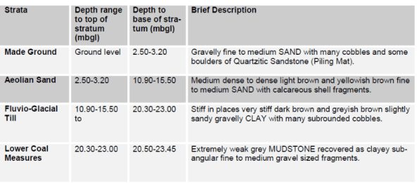
Figure 2 – Summary of Ground Conditions (WSP, 2013)
The ground water level is relatively static at 2.5m depth so is at the piling mat and sand boundary. This significantly reduces the strength of the sand (ϒ’=ϒsat– ϒdry) below that of the stiffer piling mat. Having initially used the presumed bearing capacity check (qp) from Method 2(EC7) the ground was deemed capable.
Loads
On lightweight modular structures live loads are often greater than live loads i.e. Qk>Gk. Column loads were issued by their structural engineers Fairhurst (used as a Phase 3 company before). This enabled limit state checks by Method 1. The 6no vertical loads, Figure 1, ranged from 64-440kN unfactored/service. Not a problem. However, the worst vertical to horizontal ratio at the base of the edge columns (blue dots) is 48%! I remember John saying that if H>0.1V then be worried, don’t get involved and see a specialist! Enter PET student…
Design Considerations

Figure 3 – Free body diagram
– A 1x1x1m concrete pad or paving slab is traditionally used to avoid using rebar and rarely with holding down bolts. A pad over strip foundation is planned because if L>B the zone of influence for bearing capacity increases from B to 3B deep.
– Each module uses moment connections (it’s a box that won’t tip over) so sliding is the module’s largest risk. Globally this means transferring 0.5H to the other longitudinal/transverse base. The column to pad connections are pinned.
– The sliding resistance (Rd only) from concrete to ground at 155kN/pad suffice compared to 64.5kN (0.5H). Passive resistance (Rpd) was not considered necessary at this stage.
Constraints
– It’s to have a 5-7year design life.
– The governing level is the FFL at the northern edge for level access. There is a 400mm level difference from northern to southern pads.
– The bases are to be at the minimum 450mm depth to prevent frost heave.
– I don’t want to go any wider or deeper than 1.5m as the saturated sand comes into play reducing GBC and increasing the risk of immediate (ρi) & differential (δ) settlement. Albeit the modules can manage 10mm.
Design Development
With the combined vertical and horizontal actions the two options considered (based on the site levels) are:
| Maximum pad thickness (1x1x1.5m) | Minimum pad thickness (1.5×1.5×0.5m) |
| + Increases surcharge load (qo) and so GBC | – Minimum surcharge load (qo) so GBC reduced |
| + Increases P with concrete self weight | – Decrease of P so GBC reduced |
| + Increases Rd and engages Rpd. | – Minimal sliding resistance (Rpd = 0) |
| – But increases moment (MH) & relies on Rpd | + Reduced moment (MH) |
| – Minimum depth of strong piling mat | + Increased depth of strong and stiff pile mat |
| – Increased concrete cost (3.4x) and installation | + Reduced installation time and cost |
| Risk is strength and settlement in the ground | Risk taken on effects of actions i.e. sliding |
Table 1 – Design options
I’ve used Geo5 to verify my ULS workings, but need to complete the SLS settlement checks which may be the determining factor. I have a preferred option and am hoping this forum will help confirm or quell my intentions. Especially as I’m still unsure about John’s H>0.1V… Any ideas? Or had similar issues? Or have I just slid you over the edge?
Realistically whilst there is an ideal engineering solution I am seeing first hand that the chosen solution is likely to be economically driven.
