Archive
With Great Power(Point) Comes Great Responsibility!
A quick blog about conflicting relationships on my design project.
(Credit to Glynn Tomsett for the title)

I am currently working on a project which involves developing a base concept design for upgrading the Melbourne Airport short stay car park, serving Terminals 1-3, in line with a wider airport expansion programme.
The design includes re-configuration of the current floor plans to include pick-up and drop-off, additional entry and exit ramps to cater for increased traffic flow and development of pedestrian access to the terminals.
The client, Melbourne Airport, engaged my design consultant along with an architectural firm to take on the work late last year. They subsequently contracted a PM firm to manage the project.
I attended an interim client meeting a week or two ago, which involved the design consultant (us) and architects presenting their ‘optioneering’ to the PM team ahead of delivery to Melbourne Airport’s Board of Directors. During the presentation it became apparent that we were pulling in slightly different directions from the architect, who was eager to push the ‘all singing all dancing option’ with a new orientation space (structure) in front of the car park and 2 new fandangled pedestrian bridges. It might have been that there were 20+ bodies crammed into a single glazed room with broken air-conditioning on a sweltering Melbourne day, but I could definitely sense a bit of tension in the air, so I did a bit of digging.
It turns out that when we were originally engaged on the project with the architect there was no direction on who was to lead the design effort so both parties went off in their own direction. Predictably, the architects came up with a number of flowing designs that boasted ‘confluences’ and ‘spaciality’ etc, but which required extensive structural work and in some instances were unfeasible.
By all accounts they did not take kindly to the engineering advice from Aurecon about the feasibility of some of their ideas and this caused some early conflict between the parties. It wasn’t until the PM firm were engaged that the matter was resolved after they appointed Aurecon the lead coordinator of the design effort.
From what I have seen however, this hasn’t stopped the architect from attempting to force their ideas on the project and they are obviously keen to retain as much influence/control over the design as possible, including what information gets delivered to the client.
Following the meeting I attended, the PM team identified quite a few areas in the presentation that needed further development and tightening up ahead of delivery to the Melbourne Airport Board of Directors. It was agreed that the architect who had compiled the original presentation would send it through to us work on update. What followed was a frantic 1 1/2 days of pulling together the required information ahead of the meeting.
The team were literally working to get the presentation up to scratch right up to the minute the taxi arrived to pick them up. I didn’t attend this meeting, however, when the design manager got there the architect had already arrived and had a presentation on the screen ready to go. When she explained that she had the updated presentation which the team had worked hard on, the architect refused point blank to swap it over and after some discussion (conscience not to cause a scene in front of the client) she ceded and the presentation was delivered using the original version which had only a few minor amendments made by the architect.
I was quite surprised at this level of childish behavior, an indication I suppose of the architect’s need to maintain some control over the project to justify their position and inject as much architectural scope as possible.
I wondered if anyone else had any other anecdotes about conflicts between parties from their placements?
Response to ‘Screw it!’
This blog is a response to Auggy’s post below (Screw It!) as I can’t add images to the comment (apparently there is a plug-in, but I don’t have it).
Auggy, having spoken offline about never seeing these used before, I am now seeing screw piles everywhere!
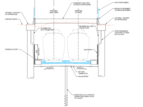
I am currently working in the design office for a level crossing removal project (Level Crossing Removal Project) which is grade separating the road and rail network at 75 locations across Melbourne. We are just about to start the developed design on two level crossings at Mentone and Cheltenham. In these areas the grade separation is achieved by lowering the rail line into a trench (approx. 9m below current ground level) and then bridging the road crossings. The works package includes retaining structures, multiple bridges, two new stations, three high-rise over rail developments and an urban regeneration project; so lots of scope to get involved in a number of disciplines.
Anyway, screw piles. At certain chainages, the trenching of the rail line will be below the ground water table and therefore a tanking slab is required. From looking at the design drawings (below) it appears that screw piles are being used as tension piles to assist the tanking slab in resisting the uplift forces. As you’ll see from the drawings the tanking slab is only 400mm thick which, without looking at the calculations, seem thin to me. This construction is undertaken close to the beach and the ground in this region is a local formation of sand and clay, so there likely considerations for heave with the design of the tanking slabs, however, I have not yet been able to uncover the geotechnical report to confirm.
In summary, it seems that the application of screw piles is more widely used than I first thought and would interesting to see if these are being used more widely in the UK?

Screw it!!
Another quick blog about something that came up in conversation yesterday with my Phase 3 mentor, which potentially has application to military construction and disaster relief operations.
BLUF
If not already used, could screw piles have an application for short to medium term RE infrastructure projects and limit groundworks and the need for reinforced concrete foundations?


BACKGROUND
My mentor here is chartered with the ICE and spent 10 or so years working in the UK, before coming out to Australia. One of the pieces of evidence he used in his CPR was his introduction of screw piles to the highways agency for the erection of gantry signs along carriageways.
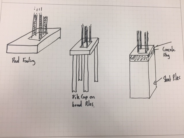
Apparently screw piles had been in use by the rail industry for some time, but the technology hadn’t made its way into other sectors. He was working on a roads project somewhere along the M6 near Birmingham which included the installation of a number of new overhead gantry signs. Traditionally the foundations for a gantry would have been one of either;
- Concrete pad footing large enough to deal with overturning actions
- Pile cap on top of bored piles
- Sheet pile box with concrete plug in the top.
Some of the considerations for the erection of gantry signs and any other roads infrastructure are;
- Time on site (Reducing the need for traffic control measures and risk to road crew of working next to live traffic)
- Ability to remove/relocate structure to accommodate future development, road widening etc.
He identified that the traditional methods described above weren’t necessarily suited to this as piling works take time and equipment, and concreting needs prep and curing times. Additionally you aren’t left with too many options but to break out the concrete if you need to move or relocate assets, which isn’t very sustainable especially if your leaving 10 or so metre piles in the ground.
SCREW PILES
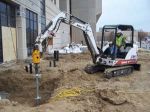
Screw piles on the other hand can be installed very quickly and need minimum plant, the attachment for screwing in the pile can be fitted to an excavator or skid steer for example, so very much scalable;


Once installed a simple grillage can be bolted to the piles to provide a connection for your gantry. Once the gantry is no longer required, the structure can simply be dismantled, the screws piles removed and re-used elsewhere.
MILITARY APPLICATION?
Something as simple as this, strikes me as a low tech, adaptable foundation solution which can be rapidly employed across different environments and avoid the need for lengthy and costly groundworks. From my brief reading, it appears the bearing capacity/hold down force required is achieved by screwing in the pile (in the example I looked at typically 2m sections which bolt together) until a specific torque is reached which determines you have reached the desired capacity. This suggests to me you might be able to avoid the need for lengthy geotechnical investigations (to some extent) and simply extend your screw piles to reach the desired capacity. This might be an over simplification…I think you can summarise the pros and cons as follows;
PROs
- Low tech
- Limited plant requirement which is standard to a plant troop
- Scalable; can easily up size piles or increase the number of piles
- Flexible; if the pile doesn’t achieve the desired capacity add sections and keep going
- Avoids ground works (especially in poor or wet ground)
- Rapid installation
- Re-useable/sustainable
CONs
- Limited capacity compared to traditional piles (This might not be an issue as unlikely to need significant capacity);
Fig below show the ultimate tensile capacity (take as a displacement of 20% of screw dia) for 100mm dia screws with different helix spacing tested at 3.05m (circles) and 6.10m (triangles). Material was 2m stiff silty-clay overlaying a deposit of lacustrine varved clay (Undrained shear strength 200KPa and 30KPa)

Note: spacing of helix’ is important in determining whether the plates act independently or in a cylindrical shear method
- Logistic burden; Probably not going to be available locally so would need to be freighted to op theatre. concrete on the other hand can generally be sourced locally
- Not suited to rock; not sure what strength of material would preclude their use.
while I was looking into these it got me thinking about a JFEE I did in Kenya a few years back which included the construction of a community centre. The previous Sqn had a number of issues with the foundations, which if I remember correctly was mainly down to the weather and rain filling the excavations and shrink/swell issues with the murrum. Could this potentially have been avoided through the use of screw piles? Screw piles seem equally suited to disaster relief operations and is seismic areas the ability to re-use them could provide an advantage over concrete foundations which presumably would become U/S after an earthquake?
THOUGHTS?
I’d be interested to hear what people think about the application of these for the Corps, or have we already used them? Has anyone come across them on one of their projects ?
“A good consultant does what we ask of them, a great consultant challenges our thinking”
I thought I would just share a quick blog after I attended a ‘Design to innovate’ workshop on my Phase 3 attachment with Aurecon today.
Aurecon is big multi-national company formed out of the merger of Africon, Connell Wagner and Ninham Strand in 2009. It’s main markets are Australia/NZ, Asia and parts of Africa. Its big selling point is that it claims to offer a different service from ‘all the other consultants out there’ and it has been described as the Google of the design world.
while I have initially been a bit cynical about this self styled approach, the quote I have titled this blog with came up in my workshop today and I thought it was quite good. The workshop then went on to explain the background to Aurecon’s thinking and introduced the ‘Blue Ocean Strategy’, a concept which was new to me and one I thought worthy of sharing for those who haven’t come across it. Rather than try and explain it myself, the short 2 1/2 minute video below will give you the idea;
Aurecon are trying to provide the next level of service in design consultancy, by improving the client experience and pushing the boundaries of the traditional design service. An example of this is that they are actively identifying future issues in their market areas, designing against them and them approaching clients with a solution to a problem they don’t necessarily yet know they are going to have.
I am not yet 100% convinced how much of what they are offering is new (and given my lack of experience I have nothing to compare against), but am interested to see what I pick up over the next couple of months. Maybe everyone else consultant has a similar pitch..?!
Introduction to Civil 3D
Introduction
Upon arrival at my Ph3 Design Office my Line Manager had me complete a Civil 3D AUTOCAD course. I am sure that many of the Civils are most likely using this or a similar software package in their design offices. However, if any of you aren’t or are only just beginning to use it then I felt this would a useful opportunity to share my experiences with you. Additionally the course deliver has permitted me to share my electronic course notes, which are a useful handrail for using Civil 3D’s specialist features.
Recommendations
The Professional Engineer Wing are invited to note the following recommendations:
- PEW should become an AUTOCAD approved course deliverer. This would formalize the CAD lectures on the course and enable students to achieve recognized AUTOCAD qualifications, which would aid them during Ph2 and Ph3.
- Civil 3D should be taught, to the Civils, as part of the PET course. As AUTOCAD is already taught as part of the course, it would be useful for students to know and understand how to use the specialist plugins available to civil engineers.
Civil 3D Specialist Features
The following is a brief summary of the specialist features that are incorporated as part of the Civil 3D software program:
- Digital Terrain Modelling. Civil 3D allows you to directly input survey data and from that data build a topographical surface. It will also reference the nomenclature of those points to input terrain features like trees, manholes etc. automatically.
- Road Design. Civil 3D has specialist features for designing alignments, profiles and corridors. Additionally it has many roadway features such as junctions, roundabouts etc. preloaded. It references data from legislative safety standards and will adjust the design to ensure they’re met.
- Grading and Earthwork Volume. Civil 3D enables you to grade with ease, this can be used for road design or simple surface manipulation for drainage etc. Additionally, it is able to use the data from grading to determine earthwork volumes.
- Gravity & Pressure Pipe Networks. Civil 3D is preloaded with the vast majority of conceivable pipe network fixtures and fittings. This makes designing and understanding the flow in pipe networks as simple as drawing polylines.
For more detailed information on how to use the various specialist features in Civil 3D, please refer to the course notes below.
Summary
So far in Ph3 I have been responsible for designing surfaces using Civil 3D to ensure that storm water on a new development will drain in accordance with the Maryland Department of Environment’s state legislation. Additionally, I will soon assume the design responsibility for foul water drainage system as part of a new military facility.
I have found the specialist tools in Civil 3D to be highly effective and huge time saver, in creating the designs for the aforementioned projects. I wholeheartedly recommend the software to my peers and hopefully you will all find it as useful as I have.
Course Notes
