Screw it!!
Another quick blog about something that came up in conversation yesterday with my Phase 3 mentor, which potentially has application to military construction and disaster relief operations.
BLUF
If not already used, could screw piles have an application for short to medium term RE infrastructure projects and limit groundworks and the need for reinforced concrete foundations?


BACKGROUND
My mentor here is chartered with the ICE and spent 10 or so years working in the UK, before coming out to Australia. One of the pieces of evidence he used in his CPR was his introduction of screw piles to the highways agency for the erection of gantry signs along carriageways.
Apparently screw piles had been in use by the rail industry for some time, but the technology hadn’t made its way into other sectors. He was working on a roads project somewhere along the M6 near Birmingham which included the installation of a number of new overhead gantry signs. Traditionally the foundations for a gantry would have been one of either;
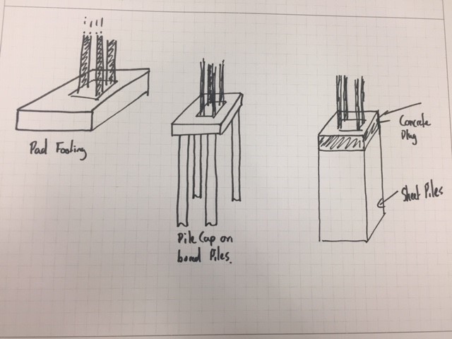
- Concrete pad footing large enough to deal with overturning actions
- Pile cap on top of bored piles
- Sheet pile box with concrete plug in the top.
Some of the considerations for the erection of gantry signs and any other roads infrastructure are;
- Time on site (Reducing the need for traffic control measures and risk to road crew of working next to live traffic)
- Ability to remove/relocate structure to accommodate future development, road widening etc.
He identified that the traditional methods described above weren’t necessarily suited to this as piling works take time and equipment, and concreting needs prep and curing times. Additionally you aren’t left with too many options but to break out the concrete if you need to move or relocate assets, which isn’t very sustainable especially if your leaving 10 or so metre piles in the ground.
SCREW PILES
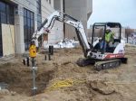
Screw piles on the other hand can be installed very quickly and need minimum plant, the attachment for screwing in the pile can be fitted to an excavator or skid steer for example, so very much scalable;


Once installed a simple grillage can be bolted to the piles to provide a connection for your gantry. Once the gantry is no longer required, the structure can simply be dismantled, the screws piles removed and re-used elsewhere.
MILITARY APPLICATION?
Something as simple as this, strikes me as a low tech, adaptable foundation solution which can be rapidly employed across different environments and avoid the need for lengthy and costly groundworks. From my brief reading, it appears the bearing capacity/hold down force required is achieved by screwing in the pile (in the example I looked at typically 2m sections which bolt together) until a specific torque is reached which determines you have reached the desired capacity. This suggests to me you might be able to avoid the need for lengthy geotechnical investigations (to some extent) and simply extend your screw piles to reach the desired capacity. This might be an over simplification…I think you can summarise the pros and cons as follows;
PROs
- Low tech
- Limited plant requirement which is standard to a plant troop
- Scalable; can easily up size piles or increase the number of piles
- Flexible; if the pile doesn’t achieve the desired capacity add sections and keep going
- Avoids ground works (especially in poor or wet ground)
- Rapid installation
- Re-useable/sustainable
CONs
- Limited capacity compared to traditional piles (This might not be an issue as unlikely to need significant capacity);
Fig below show the ultimate tensile capacity (take as a displacement of 20% of screw dia) for 100mm dia screws with different helix spacing tested at 3.05m (circles) and 6.10m (triangles). Material was 2m stiff silty-clay overlaying a deposit of lacustrine varved clay (Undrained shear strength 200KPa and 30KPa)

Note: spacing of helix’ is important in determining whether the plates act independently or in a cylindrical shear method
- Logistic burden; Probably not going to be available locally so would need to be freighted to op theatre. concrete on the other hand can generally be sourced locally
- Not suited to rock; not sure what strength of material would preclude their use.
while I was looking into these it got me thinking about a JFEE I did in Kenya a few years back which included the construction of a community centre. The previous Sqn had a number of issues with the foundations, which if I remember correctly was mainly down to the weather and rain filling the excavations and shrink/swell issues with the murrum. Could this potentially have been avoided through the use of screw piles? Screw piles seem equally suited to disaster relief operations and is seismic areas the ability to re-use them could provide an advantage over concrete foundations which presumably would become U/S after an earthquake?
THOUGHTS?
I’d be interested to hear what people think about the application of these for the Corps, or have we already used them? Has anyone come across them on one of their projects ?

Auggie,
I couldn’t agree more about the potential use of these for the Corps. I wrote my CI’s paper on helical steel piles for LSB abutment design for military and disaster relief deployments and found good papers seeming to support their use for our purposes.
I wrote the paper around a case study using some load and geotechnical data from @glynn518 ‘s Afghan LSB and the steel piles seemed to hold up in theory. The major benefits can be seen, as you point out, in logistics and time on site, ultimately reducing exposure. Using correlation installation methods you can also limit the requirement for GI. A drawback that came up in my bridge-specific discussion was the capping of pile groups and the achievement of required tolerances in the installation – capping with concrete undoes all your time and log savings but capping with steel requires higher locational accuracy and (probably) a bespoke capping plate. Maybe you’ve seen this addressed in practice already?
Being written before the full swing of the geotechnics modules of Phase 1 some of the geo intro in my paper is pretty sketchy but I think the findings on the piles should stand up. I’d be happy to share it, such as it is, if anyone is interested.
Tom
Based on my experiences on Phase 2 I would suggest the easiest to get around issues with locational accuracy would be to retrospectively mag-drill any holes for bolted connections in the capping plate. There will still need to be some tolerances to ensure appropriate load transfer, but this would be less onerous. Equally dependant on the application you might be able to simply clamp the structure onto the pile (I saw this used in a video where a static caravan was supported on screw piles).
Cracking bridge that Tom! A good video on YouTube still for those that want a visual representation of Tom’s point. (https://www.youtube.com/watch?v=LngrWXYVxaE) Have to cut and paste into the browser as I can’t work out how to hyperlink it.
For every good idea and potential demonstration of innovation there is a pathway by which it can be stifled. In a more practice and positive vein, SI(PET) and myself will now try to fond pout how to get this into the Capability system and no doubt there will be gratitude from a desk officer sonewhere for the additional burden.
I put some of these in as a grad.
An extra building (some kind of shed) got added to the scope after the PFA piling programme had finished. Was going to cost a fortune to call the rig back.
From memory, the ground was peat bog with a high water table on a site near the edge of the Thames in Woolwich.
The specialist subby put them in with a LWT and as you’ve suggested, added length until they achieved the resistance needed ~5.0m ish I think but this was 2010…