Archive
An engineer without a site… for now.
21 Moorfields will be a 17-storey office and commercial building, ear marked to become the London HQ of Deutsche Bank, in the heart of the City of London. It is a fascinating project that pushes the boundaries of light-weight steel structural design and threads the needle, in some cases quite literally, through the maze of site constraints. The project is estimated to cost upwards of £350M and is scheduled for practical completion in 2022.
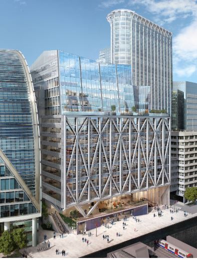
The East Face above the Crossrail station entrance
The development spans over the 6 live London Underground (LU) lines running into Moorgate Station and is immediately above the western ticket hall and access shaft for the London Liverpool Street Crossrail (CRL) station. The ‘ground floor’ of the site is also the roof of Moorgate Station and is a composite steel beam and RC slab deck supported on a series of piled columns known as the retained deck (RD).
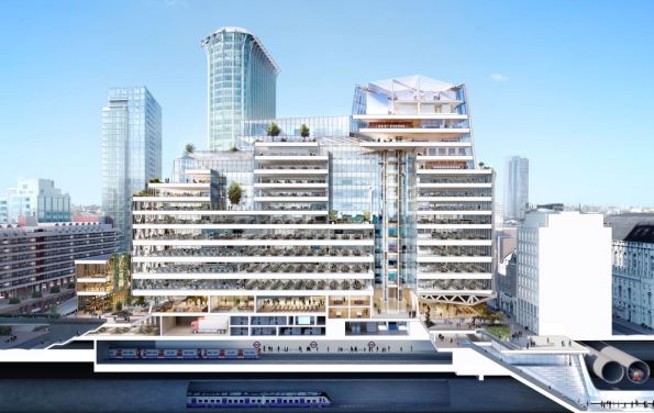
Architects impression showing the two LU lines and the Crossrail running tunnels – piling through this lot was literally threading the needle.
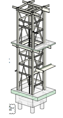
The steel superstructure spans 55m across the retained deck between two parallel rows of giant piles (the largest of which is 2.5m diameter and 57m long). Each pair of piles supports a 10-storey arch and truss to span the gap with a number of temporary works stages to ensure stability of the structure through to completion.

Truss and arch system with cantilevered East Face Truss
I have been assigned to manage the superstructure concrete package, starting with the pile heads, steel base plates and mezzanine deck, moving onto deck and beam work at every level.
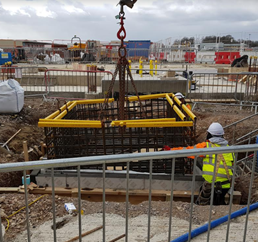
All very good but there is one small problem… we aren’t allowed on site.
The early works contractor (Mace), failed to secure the second-stage (i.e. superstructure) contract and so are vacating the site – slowly. Until they do so (the end of this week) we are sitting in an office down the road with only the high camera for site updates. To complicate this, the D&B contract between McAlpine’s (my lot) and the client (Land Securities) has yet to be signed so when works do start on Monday no one will be under contract to anyone else.

The closest any one can get to site until Monday
This enforced exile has given me ample opportunity to read into my works package and spend time with the QS team to fully understand their processes. I have also already experienced almost every type of contractual arrangement I can recall from PPO and PCM – we have PCSA, Letters of Intent, Contract Administrators Instructions, Frameworks and, hopefully soon, a JCT D&B contract.
Come Monday I can sharpen my stadia rod and don my finest hi-vis vest for a bit of Engineers in the Wild excitement on site. Until then I’m back to my bills and quotes, spreadsheets and delivery notes.
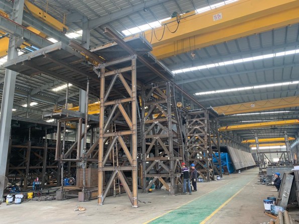
Scale of Temp Works
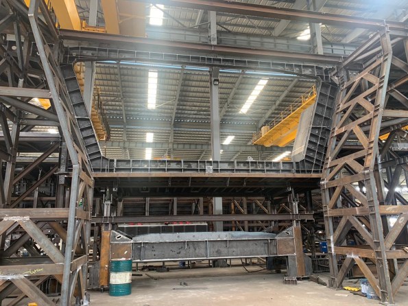
John I remember you telling us in Phase 1 you are always amazed at the scale of temp works that are involved in creating the permanent works. For my project the team are spending AUS $2.5M on establishing and running a precast yard. Below are some pictures from the trial erection currently underway in China of the pre-cast bridge segment forms. The forms are designed to be adjustable to accommodate the curves with the new segment cast next to the previous one to ensure continuity.
The average segment will be 11m long, 2m wide and 4.7m high. I’m not sure what the size the forms are but you can get an idea of their scale from the size of the people in the photographs. I’ll post more detail when they are installed on site and I understand more.

Engineering surveying
Introduction. I am now in week 3 with Multiplex on the University of Glasgow campus development, working on the £80m Research Hub project In general, the structure is a 6 storey reinforced concrete frame using flat slabs, piled foundations, steel frame roof level, pre cast concrete cladding and curtain walling. Piling finished in February with the rest of the substructure works in progress.
Issue. Along with the site engineer I have been looking at ways to improve the efficiency of our construction layout surveying. Particularly our methods used to control elevation, horizontal position and dimensions. At present we use a co-ordinate based setting out system with a Leica Total Station and are looking to improve our workflow prior to conducting as builts and setting out of MEP systems. At the moment 1 of 2 methods is typically used:
Method 1 – The junior site engineer is using a manual method. Using a dimensioned drawing, offsets from gridlines are calculated then checked on site using a reference line function.
Method 2 – The senior engineer has been replicating the project Revit model for the element, then exporting the lines to Autocad. From here the intersections are exported as a CSV and checked using the stake points function.
Neither method is ideal and so we have been looking at 2 alternatives.
Alternative 1 – Leica Building Link. This allows points to be added directly to the federated or structural Revit model. These can then be exported as an XML onto the Leica and re imported on completion to provide as builts.
+ Free, easy to use.
– Only compatible with Revit 2017, manual input method creates user error and is time consuming.

Alternative 2 – Autodesk point layout. Similar to Leica Building Link this can add points directly to the federated or structural Revit model. It has an automatic function and ability to create naming conventions.
+ Can quickly generate large numbers of points (possible to tie in with Revit families), compatible with Autocad and Navisworks, can create slab analysis heat maps.
– Relatively expensive, more complex to use compared to Leica system.


Further considerations:
Trust. Do we trust the federated /structural Revit model? It is seen as the point of truth but may contain errors. Therefore is it better for the contractor to produce their own model to identify buildability issues in advance? This can then be checked using clash detection.
Best practice. This Autodesk seminar video outlines the use of a point layout approach by a contractor in the US (https://www.autodesk.com/autodesk-university/class/Best-Practices-Utilizing-Point-Layout-2017#video). They discuss the benefits of system but note that it has taken years for them to optimise the way they integrate it and to design a workflow process.
Summary. Our current methods of engineering surveying are inefficient with room for improvement. Does anyone have experience of similar issues or advice on successful methods used in the past?
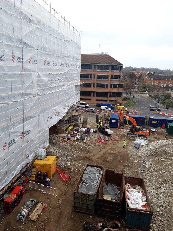
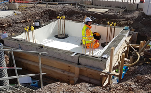
Drainage tanks in slopes
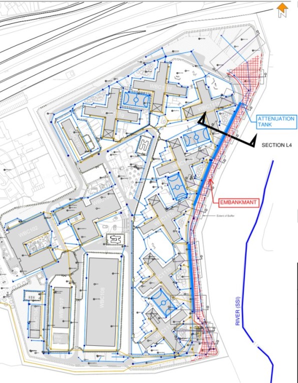
My latest Ph3 task is to coordinate the design of a reinforced slope with a surface water attenuation tank buried inside the embankment. Every part of my engineering judgement makes me think this is a bad idea – the challenge is to now engineer a solution that will work.
Background
The site lies on hill adjacent to SSI (a river and marshland). Two major risks with the sloping site;
- Excessive surface water run-off.
All surface water drainage requires attenuation to limit the discharge into the river. The redevelopment work will increase the capacity and size of the facility by 4-times the original.
- Major cut and fill exercise.
Project design specifies split levels and requires major cut and fill exercise to create plateaus for several large buildings.
Initial Design
Initial storm drainage design located attenuation tanks under sports pitches. This is an ideal scheme; large areas with minimal loading permits shallow excavations for large capacity tanks.
The Construction Phase Plan could not be achieved in unison with this scheme. Large laydown areas were required to facilitate the erection of multiple pre-cast concrete buildings simultaneously. Freedom of movement for heavy crawler cranes was integral to critical path activity. Any buried attenuation tanks would not have been able to handle these loads and the scale of temporary works to mitigate damage was not cost effective.
A large (350m-long, 6.0m high) retaining structure is necessary along the Eastern edge of the site to achieve level ground. Initial design concepts sought to utilise excavated Oadby Till (Clay) to produce a cement stabilised embankment.
Issues
Boundaries – Need to move the location of the attenuation tanks. The only available space where the tank could be buried deep enough to handle heavy construction traffic was adjacent to embankment.
Properties – Contractor is keen to use materials won on site to reduce costs (and claim some sustainability benefit). The clay alone does not have the capacity to achieve the 40-degree slope required. Confirmation of material strength following cement stabilisation can take 35+ days. This would not work with an already compressed programme.
Ground Water – A second design to reinforce the clay has been proposed but in an undrained state, the tails of geogrid would clash with the only available location of the tank.
Contamination – An underlying mudstone layer has high sulphate levels that are detrimental to cement stabilisation. Some of the boundary layers are ill-defined and risk of sulphates with the clay exists – further justification to reject cement stabilisation.
Options
My role is to understand if the following concept is achievable;
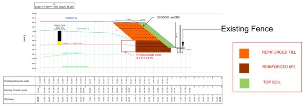
Major demolition works on site have generated a source of granular fill. This screened 6F2 could be used to form a steeper embankment and prevent a geogrid/tank clash due its superior characteristics. Preliminary calculations suggest there is insufficient quantity of this on site to form the entire embankment.
A hybrid embankment could be the solution.
Using drained granular fill to support the lower section of the embankment means shorter geogrid tails can be used next to the tank. The cut and fill clay will form the upper section of the embankment where the geogrid tails can extend above the tank. This maximises the re-use of material won on site.
I know others have looked at earth embankments – any thoughts?
Arrival on the West Gate Tunnel Project
Having completed Phase 1 of the PET(C) I have successfully transitioned onto Phase 2, working for John Holland on the West Gate Tunnel Project (WGTP) in Melbourne Australia (a fantastic city with great weather, so far). I have now been in the site office for 2 weeks and think I have enough of an understanding of the broader project and my site to impart some of my findings and thoughts on this blog.
I apologise in advance for the length of the blog, but I think this is testament to the sheer scale of works involved!
West Gate Tunnel Project Overview
The Clients have formed a partnership between the Victorian State Government and Transurban, and have selected two contractors to deliver the A$6.7 billion (approx. £3.65billion) infrastructure project. These are CPB Contractors and John Holland (CPBJH JV) in a 50:50 joint venture. Major construction work started in early 2018 with the project scheduled to open to traffic in 2022.
The project aims to deliver an alternative to the West Gate Bridge to the West of Melbourne’s city centre, close to the Central Business District, which currently caters for more than 200,000 vehicles a day, a very busy and congested route; having used this route for 2 weeks, in rush hour, I can certainly vouch for this.
The project involves building four more lanes on the West Gate Freeway, twin underground tunnels, a new bridge over the Maribyrnong River that links to an elevated road and a 14km Shared User Path (SUP). These three key areas have been split into three zones of interest; West, Tunnel and East.
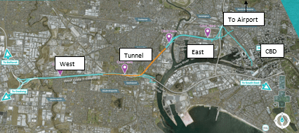
Breakdown of WGTP Zones
West Zone: Construction of four additional lanes the West Gate Freeway.
Tunnel Zone – Construction of twin tunnels running north to south, linking the M1 west of the West Gate Bridge to the North of the CBD. These tunnels are 2.8km and 4km.
East Zone –This zone will see the construction of three bridges (one freeway and two joining slip roads) across the Maribyrnong River and an elevated freeway linking into the centre of the city. This is where I have been positioned.
East Zone
Testament to the sheer size of the project, the East Zone has been split into five subzones outlined below (remembering that this is one of three). I have been placed in subzone 401 (or the ‘Maribyrnong River Crossing and Mackenzie Road’ subzone’), which will see the construction of a four-lane bridge across the Maribyrnong River with two adjacent on/off ramps (both bridges in their own rights), a connecting bridge on the east bank between both slip roads and a raised SUP (approx. 5km of the total 14km being built).


My Role
My official role within the project is as a Project Engineer working in the substructures team, of which my duties include: Planning of works, ensuring compliance with quality and procedures, monitoring safety and environmental controls and provide technical assistance to the Foreman and workforce. The task of the substructures team is to install all foundations, temporary works for the superstructure team and install all structures up to the point that the bridge decks can be installed (i.e. installation of bridge piers up to the bearings).

Example of Substructure Team’s Limit of Responsibility
Initial Thoughts and Risks
Driven preformed and bored cast-in-place piles are to be used for the foundations of the bridge, including 400mm square precast concrete piles for the sections of bridge located out of the Maribyrnong River, and steel tubular piles with reinforced concrete infill, to approx. half the depth of the pile (I believe this is for durability reasons over structural, i.e. susceptibility to corrosion of the steel tubes in the upper formations, but I hope to clarify this soon. This does make me think that there must be a method of transferring load from the RC to the steel tube at the point of RC stopping; I’m assuming through friction?), for the piers supporting the river crossing spans. Bored cast in place piles will be used for the SUP.


There have been many boreholes drilled along the alignments of each bridge as part of the GI, suggesting to me that CPBJH JV have considered ground conditions to be a key risk in the execution of these works. The GI appears to be comprehensive. Comparing the alignments, I could see that the ground changes dramatically on the East bank of the river between the three bridges. This rang alarms bells in my mind as the steel piles were clearly designed with the toe formation in the Lower Older Volcanics to achieve the required end bearing capacity. To understand how they plan to mitigate against the risk of the ground model being incorrect and the pile toe not reaching the required formation boundary, I consulted the geotechnical engineers subcontracted to design the piles who informed me that they have designed the piles 2m longer than the expected required depth for such a scenario.

Typical ‘In River Pier’ Piled Foundation


The precast piles, which are working as pile groups, are designed across the site with a toe depth that reaches formation in the Upper Volcanics formation. Again, there is clearly a risk here that these piles may not reach the required depth, based on the varying formation levels in the ground. It appears that the risk has been mitigated here by relying on the high number of boreholes conducted. I shall see how this manifests as the piling starts.
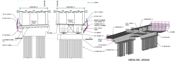
Typical ‘In Land Pier’ Precast Piled Foundation
From what I can understand, the leading factor for using driven piles across the whole project (not just 401) is the ability to limit soil excavation and disposal. When I first arrived at the area I could see vast piles of covered soil from previous excavation works. Intrigued by the reasoning for this I consulted the East Zone Manager, Alan Platt, who informed me that the soil across the whole site had been found to be contaminated and required specialist removal from site at a cost of approximately A$500 (if I remember correctly) per m³. This had not been picked up prior to the contract being agreed between the Client and CPBJH JV, with CPBJH JV unwilling to pay for the thousands of cubic metres required to be removed (clearly this would eat well into their profit margin). As it stands, from my understanding, the Client and CPBJH JV are working to find a solution to this through negotiation. I plan to dig (ignore the pun!) further into this to understand where the risk for such an event was held and how it could be avoided in the future.
In total, 738 piles are required for the permanent works alone. This does not consider for the temporary works piling, of which there is a lot; for example, 70 are required for temporary jetties alone (a whole other topic that I will look to discuss separately).
Looking at the bigger picture, it is estimated that more than 5000 piles are required for the WGTP. This led to the setup of a precast yard (something I plan on visiting soon), which will produce precast piles, bridge decks, super T’s and other precast elements. From the immense numbers of precast elements required, along with the relatively short timescale of roads opening in 2022 (not a single pile has yet been installed in the East Zone), I see procurement of precast elements as a key risk for the project and must be managed closely; piles require 14 days curing prior to delivery. It is my understanding that precast elements have not been poured for 401 yet, which makes me question our ability to begin piling precast piles on time; a quick bit of simple maths (i.e. counting days) makes this apparent. We shall see!
Summary
I have arrived on site just as site clearance and preparation has started. This has provided me with the much-needed time to understand the ‘bigger picture’ of the WGTP and the intricacies of my site (and get my head back into John Moran’s Lecture Notes!). Over the next couple of weeks, I intend on interrogating the contract in more detail to understand what is driving the project as well as how my site relates to the WGTP critical path. I look forward to ‘getting my boots dirty’ on site once the piling starts and to the challenges the lay ahead, of which I’m sure there will be plenty.
Reflections from the other side of the world…
‘G’day mate’, ‘how you going?’, ‘too easy’ and Struth, it’s hot out here… (ok so that’s enough of the Australian slang from me). Welcome to the first blog post from me on the Batemans Bay Bridge Project. After less than 2 weeks on the project I’m still trying to get my head around the technical side of things so this post will give a project overview and summarise my initial observations.
Project Background
Like me, most of you won’t have heard of Batemans Bay before. Its a small town of about 11,000 people on the East Coast of Australia in New South Wales (see map). To get here you have either a 4 hour drive south from Sydney (170 miles) or a 2 hour (94 mile) drive east from Canberra. The town straddles both banks of the River Clyde with the A1 ‘the Princes highway’ between Sydney and Melbourne passing straight through the town. On the northern side of the town, the A1 meets the B52 ‘the Kings Highway’ which is the quickest route to Canberra and the Australian Capital Territory (ACT). As a result Batemans Bay has a lot of through traffic and has become a popular destination for the Canberra residents as it has the nearest beach.
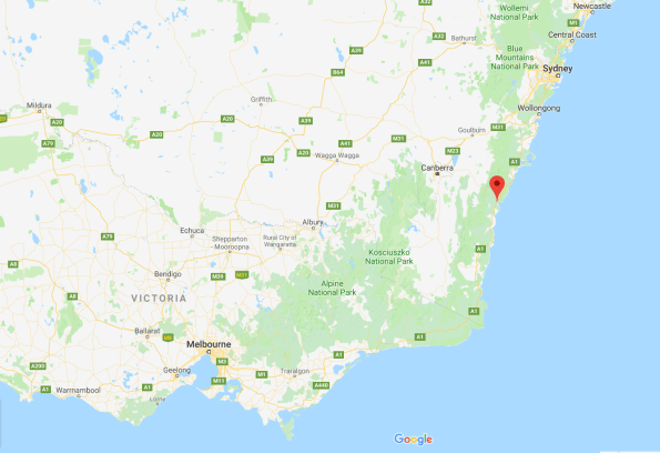
Map showing Batemans Bay location
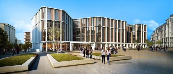
The existing road bridge connecting both sides of the river is an old 1950s steel truss bridge which supports a single carriageway. It has an unusual design incorporating a central vertical lifting span to maintain marine access upriver (see picture). With increased and heavier traffic flow along the A1, spiraling maintenance costs and congestion from bridge closures for marine access the client RMS (Roads and Maritime Services similar to Highways England) has decided to invest in a new bridge and associated junction upgrades. John Holland’s solution is a joint venture with VSL to deliver a 168 segment precast concrete box girder bridge under a Design and Construct Deed (D&C contract). This construction method was chosen to increase spans and reduce the number of piers following public consultation. An impression of the completed bridge is also shown below.
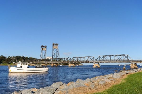
Existing Batemans Bay bridge
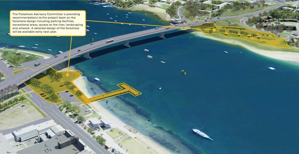
Impression of new bridge.
Further information can be found on the RMS website: https://www.rms.nsw.gov.au/projects/south-coast/batemans-bay-bridge/index.html
The delivery of the project is split into 4 overlapping phases:
Phase 1 – Design, enabling works and service diversions. This phase was due to end this month but has been extended by 3 months after additional works were added to the scope of works to ‘future-proof’ cross-river service capacity.
Phase 2 – Bridge construction. This phase is just getting underway. This week we started the establishment of the precast yard and commenced the first pier foundation pour. Initially, my job will be working as a Project Engineer to establish the precast yard bridge. This is a great opportunity to see a range of engineering including earthworks, piling, reinforced concrete, steel erection and gantry crane installation. Can you tell I’m excited about it?
Phase 3 – Junction upgrades. Elements of this phase will run concurrently with Phase 2. John Holland receives incentive bonuses for maintaining certain levels of traffic flow which will result in a staggered approach to the junction upgrades.
Phase 4 – Demolition and removal of the existing bridge including the removal of all substructure and foundations. Planning for this phase starts next year so if you fancy the job Ash Dale let me know and I’ll make sure your CV gets to the PM…
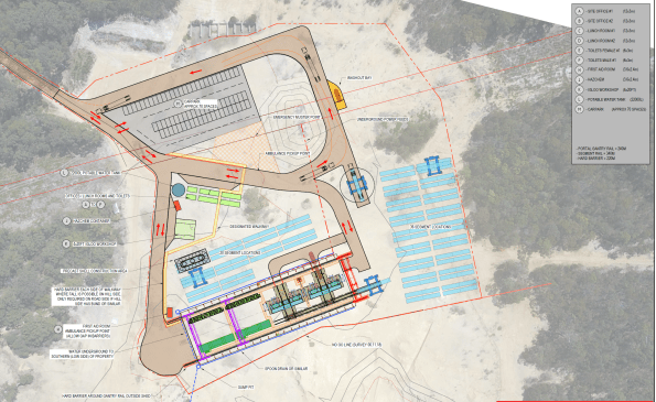
GA of proposed precast yard
Initial Observations
So what are my initial observations after 2 weeks in the office?
- Communication. The Australian construction industry and UK military both have their own slang:
– Slew cranes (mobile cranes).
– Franna cranes (not common in the UK but is used for small mobile lifting operations like a 35t TEREX or RTFL).
– FRP – Formwork, Reinforcement Pour (RC to you and me).
– Star posts (6′ pickets).
It’s definitely worth taking the time to check exactly what is meant by terms you are unfamiliar with to avoid confusion and misunderstanding. Google image search is also a great resource – it’s true, a picture paints a 1000 words and all that! We also have a French contingent from VSL as well as engineers from Asia, New Zealand and the UK. We all use the same technical language which aids communication regardless of the native tongue.
2. Commercial awareness. I’ve been surprised at how commercially involved the engineers are on site and was warned about this by the PM during my arrival chat. Here the engineers are responsible for planning/designing their work packages and resourcing them. For supply of materials this requires a minimum of 3 quotes and a purchase order. If services are required, a short form contract is needed resulting in a tender process. From my initial observations it seems that the majority of the traditional QS role sits with the engineer. There is a small commercial team here who are responsible for approvals, contract negotiation/writing and payments. I’m interested to hear if this matches the experience of the other students on placement as it was not what I expected. So what?
– Advantage: site engineers are more aware of the cost of their works so in theory produce more efficient designs and reduce overall project costs. Reduced costs = increased profit.
– Disadvantages: the organisation is split into various sub-teams working on different parts of the project. With each team resourcing their own packages there are missed opportunities to benefit from economy of scale particularly when there is limited communication between the sub-teams. This results in the duplication of tendering when works across the project could have been combined into one works package. There is also a significant amount of ‘group think’ in the office when selecting companies for tender packages which may not result in best value for money.
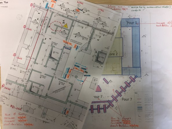
3. Drawings. The drawings for the bridge segments are incredibly complex and if I’m honest really blow my mind. Even the pre-cast yard foundation slab and steel shed erection drawings contain more detail than I’m used to. I think Phase 1 needs to cover reading and interpreting engineering drawings in more detail as I’m well behind the standard expected for the role I’m performing on site. Having example drawings at the front of the classroom during project assessments was a good start but I think more time invested in this area would make the Phase 2 transition easier to manage.
4. Military experience. The military environment provides a range of transferable skills that are really useful in the construction industry. From managing people and meeting tight deadlines to technical issues like how to build a bailey bridge (no I’m not joking they are building a bailey/Maybe bridge here) we can add heaps of value. Regardless of what you’re doing two rules remain:
- No plan survives contact.
- Keep it simple stupid.
Designing with sub standard materials
During the PEW Battlefield Study in Normandy, we came across gun positions that formed part of the Atlantic Wall. Steel was in short supply and aggregate for concrete was poor. Despite this, these structures were built, survived intense bombardment and remain 75 yrs later. 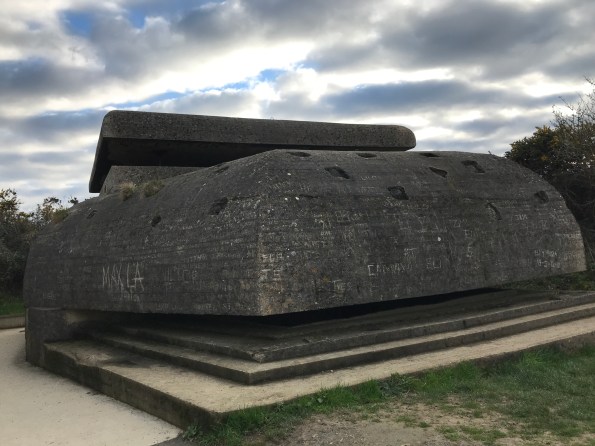

London City Airport
Having started Phase 2 with BAM at London City Airport (LCY) two weeks ago I have finally worked out enough of what is going to on provide some useful information about the project.
PROJECT OVERVIEW:
The project was tendered at £85m aiming to increase the capacity of LCY by building a new apron and taxiway as well as extending the terminal. Currently planes have to taxi up the main runway if they want to take off from the 27 end, this is
serverly restricting the capacity of the airport. BAMs role is to deliver the piles and deck and for Bechtel to follow on and construct the terminal building.
The plan is to pile into the existing dock and use precast beams and planks with an insitu topping layer to tie it all together. The project is zoned, the original plan was to undertake sectional completion, starting with P1 in Dec 2018, then P2, P3 etc. This has not gone according to plan with the rows of the piles being completed east to west length ways rather than north to south as originally planned.

P1 is basically being run as a different job to P2-5 as it involves land based operations, whereas P2-5 are being undertaken primarily from barges.
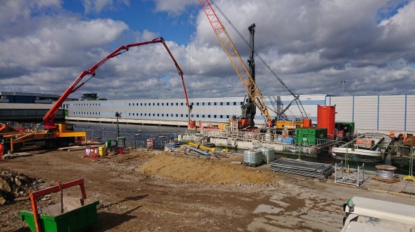
P1 Land based pouring and piling.

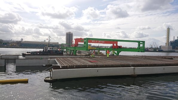
P2-5 Barge based piling, subcontracted to Skanska Cementation. Note the planks in the foreground, these are sheer links to tie in with the 150mm in-situ concrete deck.
KEY ISSUES:
Logistics. Currently there are over 4500 precast concrete elements that are being manufactured in Ireland, by Shay Murtagh, with only 20% of the total delivered there is massive pressure on them to up production. With this increase in production there is added pressure on BAM to get them placed on site, which is difficult requiring a specially built barge to place them, shown below:
Design Change. The original design was created by TPS, a subsidiary of Carillon, which obviously didn’t end well, therefore the design has been novated over to Atkins who has majorly redesigned it. They drastically increased the number of beams and planks required and the deck reinforcement complexity. This has led to BAM scrambling around trying to plug the gap between the lump sum price they tendered and what they are currently forecasting, circa £150m.
The airport is operational. The airport is open which due to a 6 degree angled safety zone from the Dock wall restricts access for the piling barge to nights only, putting the works behind from the start. It also imposes lots of other silly little constraints which cumulatively gets in the way, putting the project further behind.
Overall the client is not on side and a very adversarial relationship seems to have developed with each side looking to blame each other. Not suprising really when the project is running at least 4 months behind and £65m over budget…..
MY PART:
I have been assigned to the deck team, which is currently planning on how to install 80,000m³ of in-situ concrete onto the precast planks. This is interesting due to the amount of different types of bar layouts, 32 at the last count. This coupled with the constraints of delivery and getting things onto site, often on the night shift, requires a lot of planning.
Red Car Park Demolition
I have just started phase 2 on a demolition job for a car park on the Victoria square redevelopment in Woking. I realise that we don’t really cover demolition in phase 1 so thought I would share some photos and information on how they are doing it as a general interest piece.
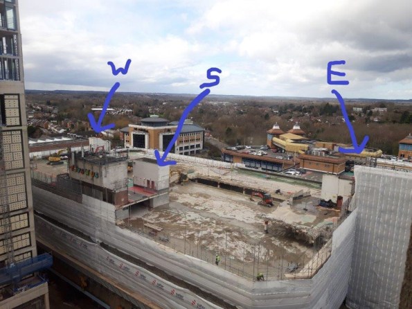
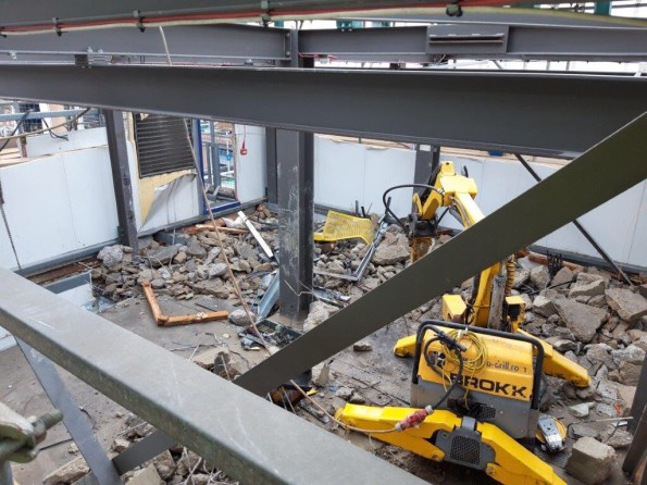
The car park has 3 cores, the South and East have a lift and staircase while the West just a staircase. The methodology is simple, the excavators work in pairs (one pecking and one munching) to remove the slab. They always work on floor up to prevent the support underneath being undermined. There was a structural load test conducted of the slab and it was determined that 1 x 13t piece of plant can stay in one structural bay with 1.5t of rubble around it to prevent collapse.
The lift cores have a concrete slab roof which is removed by a remote control pecker for H&S reasons.
When the workers start a new floor the priority is the parapet wall and then the 2m cantilever at the edge of each floor. There is a demarcation to ensure no plant is to cross onto the cantilever
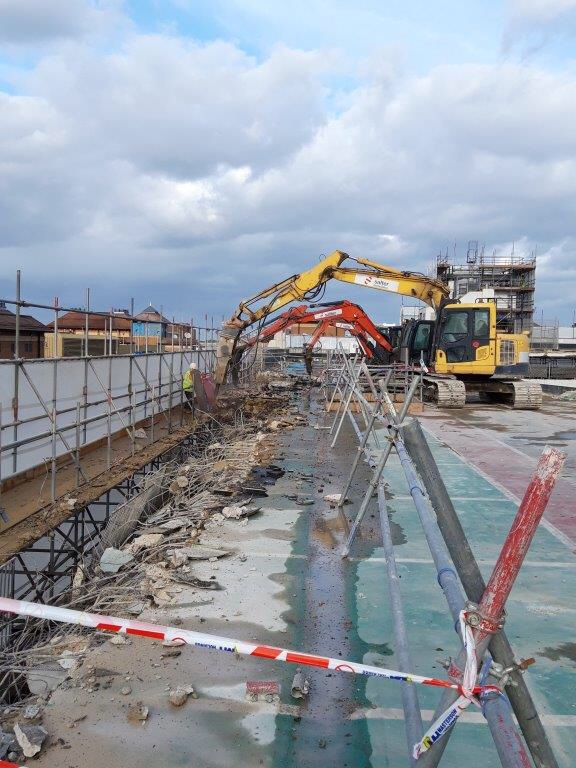
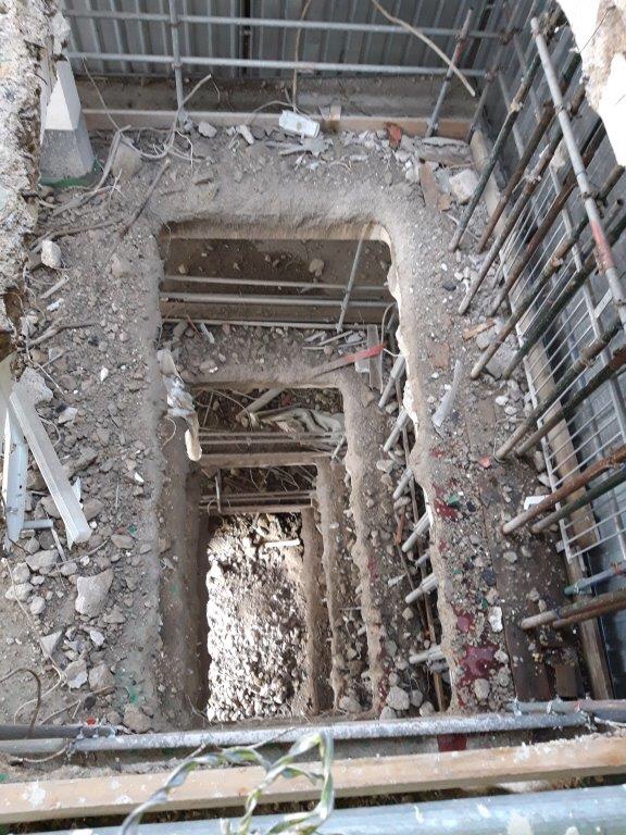
All rubble is collected by small BOBCAT shovel shifters and dropped down a shoot to the ground floor. This shoot is closely protected to prevent any labourer wondering close by.
The plant works in a methodical order, much like painting a floor in your house to ensure they don’t leave themselves trapped on a level. The rubble is then removed by a 20t excavator on street level into skips that are removed daily.
There have been issues this week with high winds ripping the protective sheeting off the scaffold which means demolition can’t take place and today the temporary water pipe used for dust suppression was broken when rubble fell down the lift shaft from the slab above and broke it in two.
Plenty of engineering challenges to come as the client seeks to keep the adjoining shopping centre open while demolishing the concrete frame around it.
Any interested questions regarding demolition send my way.
Trimming your piles
Hello all, first blog post from me (Al Bramson PET(C) 66). For those who don’t know I’m currently working at Gatwick Airport on the client side as a Project Engineer. The project I’m currently assigned to is the construction of a new passenger departure building to accommodate the A380, the big double decker plane. I’ve been inspecting some of the groundworks that has begun for this project. In particular, the pile foundations for a lift core that runs vertically through the centre of the building (see Figure 1). Kier are the subcontractor for the project and they have subcontracted the ground works to Oliver Connell.
Before Oliver Connell were to install the reinforcement cage and cast the lift pit they had left the pile reinforcement exposed (Figure 2). When I returned back to site I noticed that they had cut the pile reinforcement at the top of the pile, about 75mm above the bottom of the pile cap level. I foolishly didn’t take any photos (lesson: take lots of photos!). This cutting of rebar didn’t seem right to me as I think that there should be some reinforcement to anchor the pile to the pile cap. However, as the foundation seems to be in compression only, maybe this is not such a huge issue? The pile cap is about 1.5m deep so there is no risk of uplift as far as I can tell. Also the reinforcement cage for this is rather dense so I think they cut the pile reinforcement in order to fit the cage on top of the pile. Also possibly to save money on purchasing rebar couplers (as per Figure 4) which I understand can be collectively quite expensive.
The Senior Project Engineer seems to believe that they should have bent the rebar and definitely not cut. I checked the project drawings and they are not clear on this. I would think that the rebar would be bent if there were moments on the structure (like with a column), but the moment caused by wind loading is relatively small (bearing in mind it’s an internal lift structure). I’ve tried to research myself using the IStructE manuals with no luck. Anyone able to offer some advice?