Archive
Arrival on the West Gate Tunnel Project
Having completed Phase 1 of the PET(C) I have successfully transitioned onto Phase 2, working for John Holland on the West Gate Tunnel Project (WGTP) in Melbourne Australia (a fantastic city with great weather, so far). I have now been in the site office for 2 weeks and think I have enough of an understanding of the broader project and my site to impart some of my findings and thoughts on this blog.
I apologise in advance for the length of the blog, but I think this is testament to the sheer scale of works involved!
West Gate Tunnel Project Overview
The Clients have formed a partnership between the Victorian State Government and Transurban, and have selected two contractors to deliver the A$6.7 billion (approx. £3.65billion) infrastructure project. These are CPB Contractors and John Holland (CPBJH JV) in a 50:50 joint venture. Major construction work started in early 2018 with the project scheduled to open to traffic in 2022.
The project aims to deliver an alternative to the West Gate Bridge to the West of Melbourne’s city centre, close to the Central Business District, which currently caters for more than 200,000 vehicles a day, a very busy and congested route; having used this route for 2 weeks, in rush hour, I can certainly vouch for this.
The project involves building four more lanes on the West Gate Freeway, twin underground tunnels, a new bridge over the Maribyrnong River that links to an elevated road and a 14km Shared User Path (SUP). These three key areas have been split into three zones of interest; West, Tunnel and East.
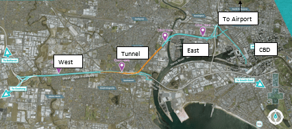
Breakdown of WGTP Zones
West Zone: Construction of four additional lanes the West Gate Freeway.
Tunnel Zone – Construction of twin tunnels running north to south, linking the M1 west of the West Gate Bridge to the North of the CBD. These tunnels are 2.8km and 4km.
East Zone –This zone will see the construction of three bridges (one freeway and two joining slip roads) across the Maribyrnong River and an elevated freeway linking into the centre of the city. This is where I have been positioned.
East Zone
Testament to the sheer size of the project, the East Zone has been split into five subzones outlined below (remembering that this is one of three). I have been placed in subzone 401 (or the ‘Maribyrnong River Crossing and Mackenzie Road’ subzone’), which will see the construction of a four-lane bridge across the Maribyrnong River with two adjacent on/off ramps (both bridges in their own rights), a connecting bridge on the east bank between both slip roads and a raised SUP (approx. 5km of the total 14km being built).


My Role
My official role within the project is as a Project Engineer working in the substructures team, of which my duties include: Planning of works, ensuring compliance with quality and procedures, monitoring safety and environmental controls and provide technical assistance to the Foreman and workforce. The task of the substructures team is to install all foundations, temporary works for the superstructure team and install all structures up to the point that the bridge decks can be installed (i.e. installation of bridge piers up to the bearings).

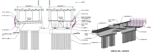
Example of Substructure Team’s Limit of Responsibility
Initial Thoughts and Risks
Driven preformed and bored cast-in-place piles are to be used for the foundations of the bridge, including 400mm square precast concrete piles for the sections of bridge located out of the Maribyrnong River, and steel tubular piles with reinforced concrete infill, to approx. half the depth of the pile (I believe this is for durability reasons over structural, i.e. susceptibility to corrosion of the steel tubes in the upper formations, but I hope to clarify this soon. This does make me think that there must be a method of transferring load from the RC to the steel tube at the point of RC stopping; I’m assuming through friction?), for the piers supporting the river crossing spans. Bored cast in place piles will be used for the SUP.


There have been many boreholes drilled along the alignments of each bridge as part of the GI, suggesting to me that CPBJH JV have considered ground conditions to be a key risk in the execution of these works. The GI appears to be comprehensive. Comparing the alignments, I could see that the ground changes dramatically on the East bank of the river between the three bridges. This rang alarms bells in my mind as the steel piles were clearly designed with the toe formation in the Lower Older Volcanics to achieve the required end bearing capacity. To understand how they plan to mitigate against the risk of the ground model being incorrect and the pile toe not reaching the required formation boundary, I consulted the geotechnical engineers subcontracted to design the piles who informed me that they have designed the piles 2m longer than the expected required depth for such a scenario.

Typical ‘In River Pier’ Piled Foundation


The precast piles, which are working as pile groups, are designed across the site with a toe depth that reaches formation in the Upper Volcanics formation. Again, there is clearly a risk here that these piles may not reach the required depth, based on the varying formation levels in the ground. It appears that the risk has been mitigated here by relying on the high number of boreholes conducted. I shall see how this manifests as the piling starts.
Typical ‘In Land Pier’ Precast Piled Foundation
From what I can understand, the leading factor for using driven piles across the whole project (not just 401) is the ability to limit soil excavation and disposal. When I first arrived at the area I could see vast piles of covered soil from previous excavation works. Intrigued by the reasoning for this I consulted the East Zone Manager, Alan Platt, who informed me that the soil across the whole site had been found to be contaminated and required specialist removal from site at a cost of approximately A$500 (if I remember correctly) per m³. This had not been picked up prior to the contract being agreed between the Client and CPBJH JV, with CPBJH JV unwilling to pay for the thousands of cubic metres required to be removed (clearly this would eat well into their profit margin). As it stands, from my understanding, the Client and CPBJH JV are working to find a solution to this through negotiation. I plan to dig (ignore the pun!) further into this to understand where the risk for such an event was held and how it could be avoided in the future.
In total, 738 piles are required for the permanent works alone. This does not consider for the temporary works piling, of which there is a lot; for example, 70 are required for temporary jetties alone (a whole other topic that I will look to discuss separately).
Looking at the bigger picture, it is estimated that more than 5000 piles are required for the WGTP. This led to the setup of a precast yard (something I plan on visiting soon), which will produce precast piles, bridge decks, super T’s and other precast elements. From the immense numbers of precast elements required, along with the relatively short timescale of roads opening in 2022 (not a single pile has yet been installed in the East Zone), I see procurement of precast elements as a key risk for the project and must be managed closely; piles require 14 days curing prior to delivery. It is my understanding that precast elements have not been poured for 401 yet, which makes me question our ability to begin piling precast piles on time; a quick bit of simple maths (i.e. counting days) makes this apparent. We shall see!
Summary
I have arrived on site just as site clearance and preparation has started. This has provided me with the much-needed time to understand the ‘bigger picture’ of the WGTP and the intricacies of my site (and get my head back into John Moran’s Lecture Notes!). Over the next couple of weeks, I intend on interrogating the contract in more detail to understand what is driving the project as well as how my site relates to the WGTP critical path. I look forward to ‘getting my boots dirty’ on site once the piling starts and to the challenges the lay ahead, of which I’m sure there will be plenty.
Reflections from the other side of the world…
‘G’day mate’, ‘how you going?’, ‘too easy’ and Struth, it’s hot out here… (ok so that’s enough of the Australian slang from me). Welcome to the first blog post from me on the Batemans Bay Bridge Project. After less than 2 weeks on the project I’m still trying to get my head around the technical side of things so this post will give a project overview and summarise my initial observations.
Project Background
Like me, most of you won’t have heard of Batemans Bay before. Its a small town of about 11,000 people on the East Coast of Australia in New South Wales (see map). To get here you have either a 4 hour drive south from Sydney (170 miles) or a 2 hour (94 mile) drive east from Canberra. The town straddles both banks of the River Clyde with the A1 ‘the Princes highway’ between Sydney and Melbourne passing straight through the town. On the northern side of the town, the A1 meets the B52 ‘the Kings Highway’ which is the quickest route to Canberra and the Australian Capital Territory (ACT). As a result Batemans Bay has a lot of through traffic and has become a popular destination for the Canberra residents as it has the nearest beach.
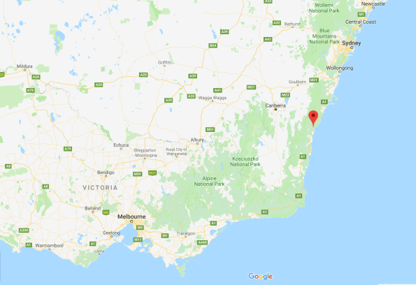
Map showing Batemans Bay location
The existing road bridge connecting both sides of the river is an old 1950s steel truss bridge which supports a single carriageway. It has an unusual design incorporating a central vertical lifting span to maintain marine access upriver (see picture). With increased and heavier traffic flow along the A1, spiraling maintenance costs and congestion from bridge closures for marine access the client RMS (Roads and Maritime Services similar to Highways England) has decided to invest in a new bridge and associated junction upgrades. John Holland’s solution is a joint venture with VSL to deliver a 168 segment precast concrete box girder bridge under a Design and Construct Deed (D&C contract). This construction method was chosen to increase spans and reduce the number of piers following public consultation. An impression of the completed bridge is also shown below.
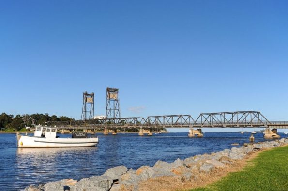
Existing Batemans Bay bridge
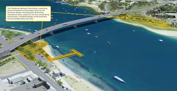
Impression of new bridge.
Further information can be found on the RMS website: https://www.rms.nsw.gov.au/projects/south-coast/batemans-bay-bridge/index.html
The delivery of the project is split into 4 overlapping phases:
Phase 1 – Design, enabling works and service diversions. This phase was due to end this month but has been extended by 3 months after additional works were added to the scope of works to ‘future-proof’ cross-river service capacity.
Phase 2 – Bridge construction. This phase is just getting underway. This week we started the establishment of the precast yard and commenced the first pier foundation pour. Initially, my job will be working as a Project Engineer to establish the precast yard bridge. This is a great opportunity to see a range of engineering including earthworks, piling, reinforced concrete, steel erection and gantry crane installation. Can you tell I’m excited about it?
Phase 3 – Junction upgrades. Elements of this phase will run concurrently with Phase 2. John Holland receives incentive bonuses for maintaining certain levels of traffic flow which will result in a staggered approach to the junction upgrades.
Phase 4 – Demolition and removal of the existing bridge including the removal of all substructure and foundations. Planning for this phase starts next year so if you fancy the job Ash Dale let me know and I’ll make sure your CV gets to the PM…
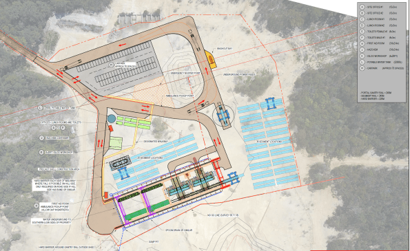
GA of proposed precast yard
Initial Observations
So what are my initial observations after 2 weeks in the office?
- Communication. The Australian construction industry and UK military both have their own slang:
– Slew cranes (mobile cranes).
– Franna cranes (not common in the UK but is used for small mobile lifting operations like a 35t TEREX or RTFL).
– FRP – Formwork, Reinforcement Pour (RC to you and me).
– Star posts (6′ pickets).
It’s definitely worth taking the time to check exactly what is meant by terms you are unfamiliar with to avoid confusion and misunderstanding. Google image search is also a great resource – it’s true, a picture paints a 1000 words and all that! We also have a French contingent from VSL as well as engineers from Asia, New Zealand and the UK. We all use the same technical language which aids communication regardless of the native tongue.
2. Commercial awareness. I’ve been surprised at how commercially involved the engineers are on site and was warned about this by the PM during my arrival chat. Here the engineers are responsible for planning/designing their work packages and resourcing them. For supply of materials this requires a minimum of 3 quotes and a purchase order. If services are required, a short form contract is needed resulting in a tender process. From my initial observations it seems that the majority of the traditional QS role sits with the engineer. There is a small commercial team here who are responsible for approvals, contract negotiation/writing and payments. I’m interested to hear if this matches the experience of the other students on placement as it was not what I expected. So what?
– Advantage: site engineers are more aware of the cost of their works so in theory produce more efficient designs and reduce overall project costs. Reduced costs = increased profit.
– Disadvantages: the organisation is split into various sub-teams working on different parts of the project. With each team resourcing their own packages there are missed opportunities to benefit from economy of scale particularly when there is limited communication between the sub-teams. This results in the duplication of tendering when works across the project could have been combined into one works package. There is also a significant amount of ‘group think’ in the office when selecting companies for tender packages which may not result in best value for money.
3. Drawings. The drawings for the bridge segments are incredibly complex and if I’m honest really blow my mind. Even the pre-cast yard foundation slab and steel shed erection drawings contain more detail than I’m used to. I think Phase 1 needs to cover reading and interpreting engineering drawings in more detail as I’m well behind the standard expected for the role I’m performing on site. Having example drawings at the front of the classroom during project assessments was a good start but I think more time invested in this area would make the Phase 2 transition easier to manage.
4. Military experience. The military environment provides a range of transferable skills that are really useful in the construction industry. From managing people and meeting tight deadlines to technical issues like how to build a bailey bridge (no I’m not joking they are building a bailey/Maybe bridge here) we can add heaps of value. Regardless of what you’re doing two rules remain:
- No plan survives contact.
- Keep it simple stupid.
