Archive
When things don’t go to plan… engineer your way out of trouble!
Over the last few weeks we have experienced a number of issues on site. For those who missed my first post, I am working on a bridge replacement project in Australia. My current job is working with the team to establish the precast yard for segment production. This post covers the main problems encountered so far and how we are engineering our way out of trouble…
- Design. The precast yard is essentially temporary works on a large scale. To maximise profit, the contractor spent limited time and money as possible on the consultant design. The result was independent design teams working on the earthworks, drainage, structural design and environmental plans. This approach could have worked however, no attempt was made to overlay and combine the designs. Needless to say there have been a number of oversights which have only been identified on site during construction. This issue has been compounded by a lack of access to CAD drawing files on site (and project level) and a lack of setting out information on the drawings. This has resulted in issues with the earthworks and drainage across site.
Lesson Identified: saving cost on design = additional cost in execution.
- Earthworks. A GPS grader was chosen to perform the majority of the earthworks due to ground conditions and speed, resulting in cost savings but has not proven to be the case. The grader was used to cut/determine the majority of levels on site. Although the technology is pretty accurate (verified by an on-site surveyor), the machine is only as good as earthwork model provided. Due to design constraints, the model was oversimplified and contained a number of errors. The result has been a lot of repeated work and significant overspend on earthworks. We are now using a surveyor to set out and confirm the remaining earthwork levels which is an additional cost.
Lessons Identified: (1) Technology is great when resourced correctly. (2) Always check levels with a surveyor.
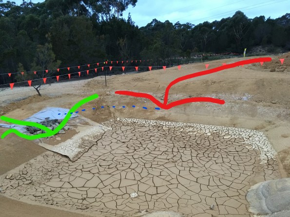
- Drainage (1). As alluded to earlier, the precast yard design has not been completely coherent. An example of this is the drainage ditch along the eastern boundary of the site. The ditch is shown in different locations on the stormwater and environmental plans (without setting out data) and is omitted completely from the site GA dwg. The ditch was initially constructed as shown on the environmental plan (alignment marked red in picture below) but was later identified during an as-built survey as being upto 10m into the segment storage area. This effectively halved the precast yard segment storage capacity and was considered unworkable. The solution was to move the ditch onto the site boundary (alignment marked in green) and spend even more money on earthworks!

For those with a keen eye, the embankment near the trees is well in excess of the approved design batter (45 degrees). I anticipated this and highlighted my concerns to the Superintendent and Precast PM prior to moving the ditch. The PM (a chartered Australian Civil Engineer) shared my concerns but it was decided to proceed. If required Superintendent agreed to stabilise (or potentially shotcrete) the slope later if necessary but nothing will be done initially to save money. I’m interested to see how the slope copes during the next period of heavy rain.
Lessons Identified: (1) If it doesn’t feel right trust your instincts. (2) As-built surveys can help identify issues early before they become a big problem (or nightmare to fix later).
- Drainage (2). During the early earthwork stages, one Supervisor decided to go a little ‘off plan’ and decided to connect a sedimentation pond at the northeastern corner of the site with the eastern ditch (shown above). This would remove the need for the sedimentation pond and allow free drainage around the site to a larger off-site sedimentation pond. Although a good idea in principle, after some extensive earthworks to connect the two features, it was realised that the Supervisor had failed to check the required levels. The picture below shows the eastern ditch highlighted in red and the north ‘overflow’ channel in green. The overflow outlet level is approximately 500mm lower than the eastern drainage ditch outlet. To work as the Supervisor intended the entire eastern ditch would need to be dug lower. Due to the earthworks overspend and slope stability issues this won’t happen.
Lesson Identified: Don’t cuff it, double check it.
- Piling. Due to the weight of the segments, deep foundations are required for the segment mould casting area. The solution was 52 No. 350mm square precast piles with predicted toe depths varying between 6.5m and 13.0m. Having only seen videos of piling I was excited to see live piling in action so made sure I had a good view for the first drive. The left-hand picture was taken after the first two piles had refused early at approximately 6m and 4m above the intended toe depth. The piling team started ‘sucking teeth’ over the more difficult than expected driving conditions which started a mild panic in the project team as the contract cost of pile ‘break-back’ per meter was going to cost a fortune. As briefed during the Retaining Soils module the piling crew left the piles to settle for over 24 hours and attempted to re-drive with an increased hammer weight. The right-hand picture shows a photograph of the piles at the end of driving. The good news was the first two piles were driven further (up to 3m); the bad news was that a number of piles were significantly proud. After searching for ‘experienced-wisdom’ and seeking advice from the piling sub-contractor, a method was devised to cut-off the excessively proud piles to reduce the amount of ‘break-back’ required. Pile Driving Analyser (PDA) tests were conducted on 5 piles which indicate the piles have an ultimate geotechnical capacity in excess of that required.


Lessons identified: (1) Don’t panic too soon. (2) The amount a pile can still be driven following an initial refusal is surprising.
- Reinforced Concrete Foundation Pour. This week we started the foundation pours. The first pour of 167m3 went relatively smoothly however the second 310m3 pour was slightly more dramatic. With pressure on to complete the pour as planned so the concreters could fly home for Easter and the steel erection team could start straight after Easter a big push was required. We initially made good progress and placed 200m3 before the sub-contractor’s concrete boom pump malfunctioned. For safety reasons, the Superintendent immediately prevented further use of the boom pump and instructed for the remaining section of the pour to be completed from the back of the cement mixers. There was no standby boom pump on site and as Batemans Bay is a small coastal town so there was no hope of getting a replacement at short notice. Due to site constraints, the remaining 100m3 in the next pour section wasn’t accessible by cement mixer so the rest of the pour had to be postponed. This initiated a chain reaction of phone calls between the batching plant, boom pump hire company, concreters and sub-contractors to rearrange for the next day. The biggest immediate problem was the 10m3 of concrete already on site that would be in excess of the completed section. We rapidly made plans to use some of the concrete as blinding for subsequent foundation pours however over 7m3 of concrete was wasted as alternative pour locations were not ready.
Lesson Identified: Always prepare an alternative pour location for excess concrete disposal.
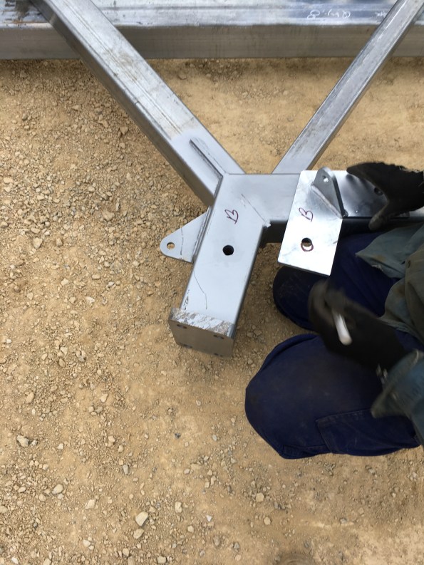
- Steel bracket fabrication. We have also been having issues with the steel frame provided by the fabricator. Their deliveries have been fairly hit and miss and not in a logical sequence to facilitate erection from one end of the structure. With the steel erectors on site this week we identified that all the plates supplied have incorrect bolt holes with each plate requiring a different remedy (picture below illustrates where the bolt hole should be). Due to the Easter and ANZAC Day public holidays, it would take two weeks to get the plates fabricated correctly. With hefty liquidated damages (LDs) for any components not on site before 26 Apr, the Superintendent brokered a deal between the steel fabricator and our steel erectors to adapt the plates on site and keep the steel erection on track. The steel erectors have conducted ground level on-site pre-fabrication this week as we are still awaiting delivery of key bracing components before the structure can be erected. With one delivery expected tomorrow (26 Apr) it will be interesting to see which items are on site before the cutoff and how the LDs work out. The good news is tomorrow I have to account for all the steel held on site – and I thought weapon serial checks were on hold for the next 18 months…
Lesson Identified: It’s the little things that stop the big things from happening…
Top cover
I was walking to my demolition site last week and noticed a peculiar pattern on a concrete slab which had been poured as part of the new retail area.
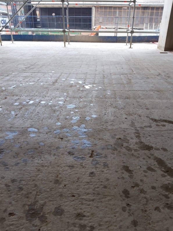
It seemed unintentional so I asked a surveyor who was there when it was poured (as it was before my time) and he told me what happened. I thought it was interesting so I thought I would share it.
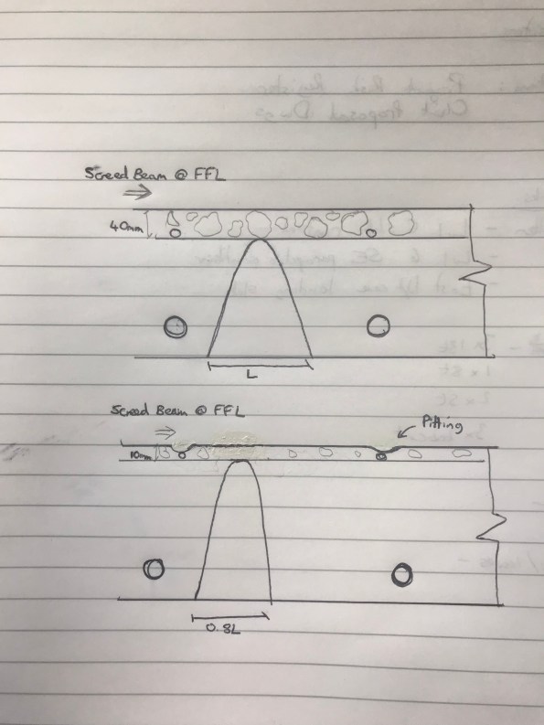
The slab is constructed with top and bottom reinforcement. The mesh at the top of the slab is held in suspension by small “chairs”. The problem arose from the chairs being the wrong size and therefore pushing the top mesh higher than it should have been. As the FFL was set the mesh ate into the top cover which was only 10mm where it should have been 40mm.
When the screed beam finished the aggregate in the concrete was pushed off the mesh as it was too big to sit between the FFL and the mesh. This meant that in the exact local of the mesh, there is no aggregate and a weaker cement mixture left. This has led to local settling of the slab in the exact footprint of the mesh.
It seems that this could have been rectified by a pre pour check and if it was identified the mesh was too high then the legs could have been spread out to lower the top, the legs clipped or smaller chairs ordered.
For whatever reason this didn’t happen. The fact this has been left might mean that the floor finish might cover these sins but it will not help with the durability of this slab.
How to put overweight building design on a diet?
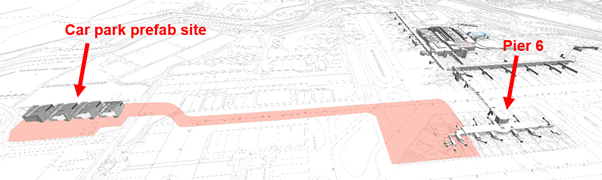
The largest project at Gatwick ongoing at the moment is the western extension to Pier 6 at the North Terminal. The project is currently at RIBA 3 (developed design) stage. In order to mitigate the impact to aircraft operations, the construction method involves building a steel structure from four separate modules off-site at a car park. It is intended that as much of the construction work is prefabricated here before the modules being moved on Self-Propelled Modular Transporters (SPMTs) across the airport to connect to the existing Pier 6 building (see Figure 1). I understand that something like this, where the whole module will be fitted out off site, has not been done before, therefore brings with it some interesting challenges.
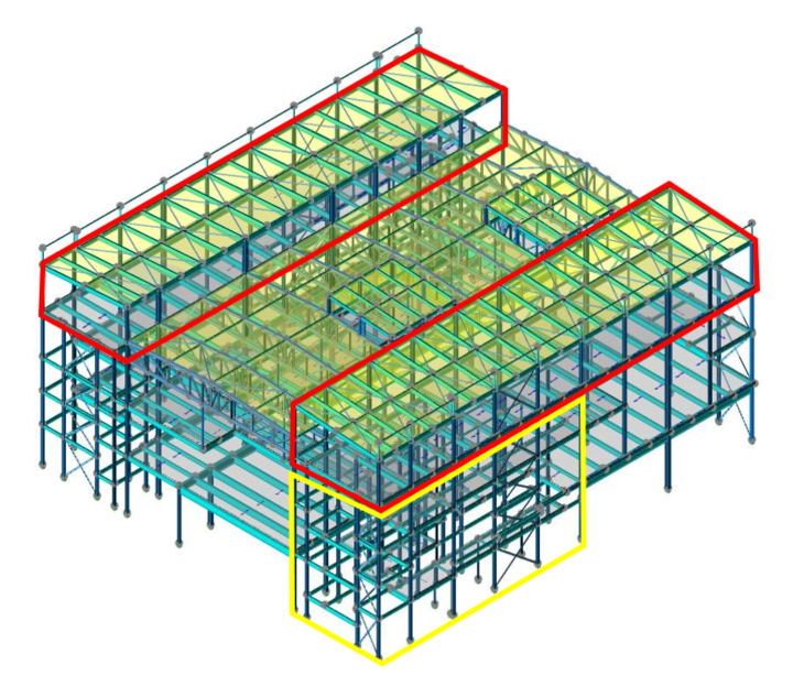
The original module design can be seen in Figure 2 below. One of the biggest problems that has developed during the design stage has been the addition to the original module design of a significant amount of steel (1000 tons +!)[. This has largely come about due to a number of factors, one of the most significant being the key stakeholders changing their requirements part way through the project. This has meant that larger Vertical Circulation Cores (VCCs) are required, increasing the steel required for the modules.
The revised design (see Figure 3) has seen the plant rooms on the roof reduced and the overall structural design simplified. Because of this simplification, larger columns and beams are now required, increasing the permanent loads despite the reduction of the plant rooms. I understand that the design was simplified for better buildability and easier ability to move by SPMT.
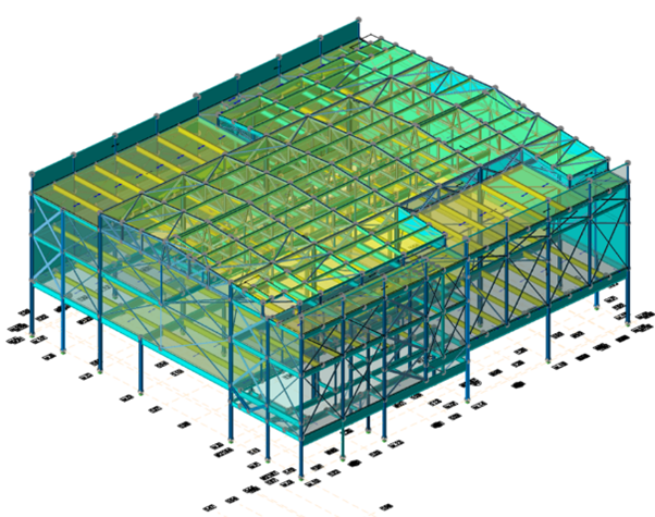
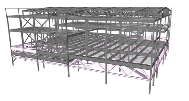
Additional temporary steel has also been required due to the need to keep the structure as rigid as possible during the SPMT move across the airfield. This has added a significant cost on top of the forecasted costs originally envisaged. Note in figure 3 that there is a lot of temporary cross-bracing to keep the structure rigid during the SPMT move. The cross bracing would prevent lateral movement though I believe it would not overcome torsional effects of the SPMT move, i.e. it would twist. Figure 4 shows a potential solution where the building sits on a truss. This uses more steel than the other design but allows the building to transfer loads much more effectively to the SPMTs.
Gatwick are negotiating with the designer on further compromises to this issue. The structural designer has added up to a 15% addition of steel to their calculations for connection detailing and 10% for ‘contingency allowance’. I’m not clear how they have come to these figures but do they seem right?
The modules also do not impose a uniform load, with the VCC part of the structure imposing more load than other areas. To mitigate this the SPMTs have been arranged in groups of three (see figure 5 below), much like the point support of a three legged wooden stool. Interestingly the module loading is distributed into four quadrants and it was originally suggested that the SPMTs also be grouped likewise. However, the SPMT contractor has stated that a four group method is not preferred due to additional control complexity during transportation.
All of this makes me wonder whether this method of construction, whilst quite innovative, has come with additional (expensive) obstacles. It may have been more economic to build the pier on site, with most of the work being done during operational stand-down hours at night. This however may have added additional time to the project. I look forward to seeing how this project evolves in the future.
What’s a TMR? – Traditional Vs. Whole Footprint Jump Form
Hello all,
It’s been a little while since I posted and I also realised I failed to follow through on my promise to add more information from my previous post ‘Innovative Jump Form System for the Residential Tower’ if you’ve not read that one feel free to check it out.
With the deployment of the junior course and what must be the impending deadline of submitting TMR 1, I though this blog might kill two birds with one stone and not take me too much time doing it.
- It might provide some insight on how someone has formatted and worded a TMR. This is by no means ‘the’ way of doing it its just ‘my’ way but it has severed to get me though with reasonable marks. I know how hard it was to get into the swing of TMRs especially setting up how you want them to look and feel.
- The topic of the TMR is a comparison of a traditional jump form system with the new style whole footprint system deployed on my site during my Phase 2. I managed to get myself a role as the Site Engineer for vertical elements and so was working with it daily. Thus this fulfils my previous promise.
At this LINK is the TMR itself along with the supporting Annex’s. I have also put in John’s comments and feedback following my submission so you can see the areas I could have improved, I have removed the marks suffice to say it scored over 50%.
Happy to answer any questions or comments if anyone has any. Hopefully this is useful to someone and doesn’t come across as self serving, believe me that is not my intent.
Bye Bye Tolerances
Yesterday on site we had an interesting discussion about an issue which has been in the background for a while, which everyone has been ignoring until it’s actually preventing concrete being laid.
Issue: The pavement thickness of the client has been specified as 150mm + 20mm. The precast secondary elements they are resting on are designed to deflect up to 40mm, the primary beams 6mm and the piles to settle up to 20mm. Whilst we haven’t actually been given FPLs (finished pavement level) by the designer yet, they are coming and we will have to be within +/-6mm to be compliant with the spec.
This is a similar problem to on Joe Murrows site, we can’t however back prop to limit deflection as it is over water!
This has raised the following questions:
- At which point does out liability end? FPL which change over time therefore so long as it’s less than 20mm is that okay?
- We have raised RFIs regarding which is the overriding factor, pavement thickness or FPL. We think it is going to be FPL, but if it is do we risk overloading the planks to get this? Atkins have designed for the concrete to be up to 45mm thicker to account for this, it is likely to be tight at midspan though…. This also doesn’t take into account the as built levels being lower that design.
- How do we monitor this settlement?
- Currently we are monitoring the levels at the four stages highlighted below. What we have suggested is that monitor selected areas, these include areas under the most loading and where the piles might be bearing on different boundarys to those it was designed for. These are being monitored weekly at top of plank level, point 3.
- At the moment it all comes down to resources, it is isn’t in the spec that we have to monitor it, therefore there is no money for it. A very shortsighted viewpoint I think as the elements listed below are intrinsically linked to knowing how much movement there is!
Areas where we are recording levels
Any ideas on how we could:
1. Cheaply and easily monitor settlement accurately?
2. Accurately measure Deflection?
Steel Pile Fabrication
G’day from Sunny Melbourne! this blog will be much shorter than my last!
I’m sure all the Phase 2 guys remember our trip to NU Steel back on Phase 1 prior to Ex STEEL (that might seem like a life time ago already for some!), where John provided us with the opportunity to see the steel fabrication of gantry elements etc.
I thought I’d just share some photos of the fabrication process being undertaken by ABFI Steel Group (specialists in the fabrication of large diameter steel and pipes – https://abfisteel.com.au/), the specialist subcontractors that have been contracted to fabricate and deliver the steel tubular piles being installed for marine based pier foundations in the Maribyrnong River, Melbourne.

Typical marine Pier Section
The steel piles being installed in the river are 36mm thick, 2.2m in diameter (in the largest cases) and are being driven up to 35m RL. They have been designed to a maximum axial compression load of 28.6MN each. This poses a serious logistical challenge for delivery to site, considering the piles are being manufactured in Wacol, Queensland (only a 1021 mile drive – or 17.5 hours … in a car … ) and will be delivered by road. Clearly at 35m in length, the piles will require splicing on site, with sections being fabricated at roughly 16m sections. This will increase the number of deliveries, and of cause, creates issues with managing quality of splicing on site (a process that is being reviewed, in detail, as I write this). I will be involved in the Inspection Testing Plan (ITP) for these splices and will be required to ensure QA processes are conducted in accordance with the ITP.
Example of a Steel pipe Delivery by ABFI.
Below are pictures from the fabricator’s workshop of piles being fabricated (unfortunately, at over 1000 miles away, I was not able to pop over and get the pictures myself). As can be seen, some serious work is being conducted in this fabrication process as tolerances/quality are tight. This has led to some serious interrogation of the subcontractors method of works and QA system to ensure the piles are competent once manufactured.
I look forward to seeing the piles arrive on site and being installed as part of a complex method involving two marine barges to facilitate lifting and driving of the piles in the river.


How to pile through a railway station
As we aren’t able to add pictures to the replies, this is a quick post to answer Richard’s questions about the pile heads.
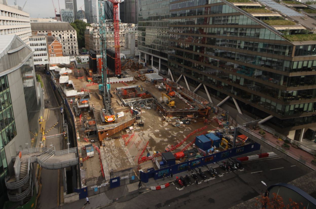
First things first – the time lapse camera looks west, from the ‘back’ of the site into the narrowest end. The view in my first blog An engineer without a site… for now. shows the remnants of a considerable amount of steel. This steel was formerly a piling grillage which can be made out below.
August 2018 – piling from the grillage at 21 Moorfields
The retained deck (RD),a composite steel beam and RC deck which is both the ground floor of this site and the roof of Moorgate station, is only rated for 10kPa UDLs so could not bear the weight of piling rigs. To get these rigs on site a grillage scheme was installed (3000T of steel – more impressive temporary works!) on plinths tied into hard-points on the RD.
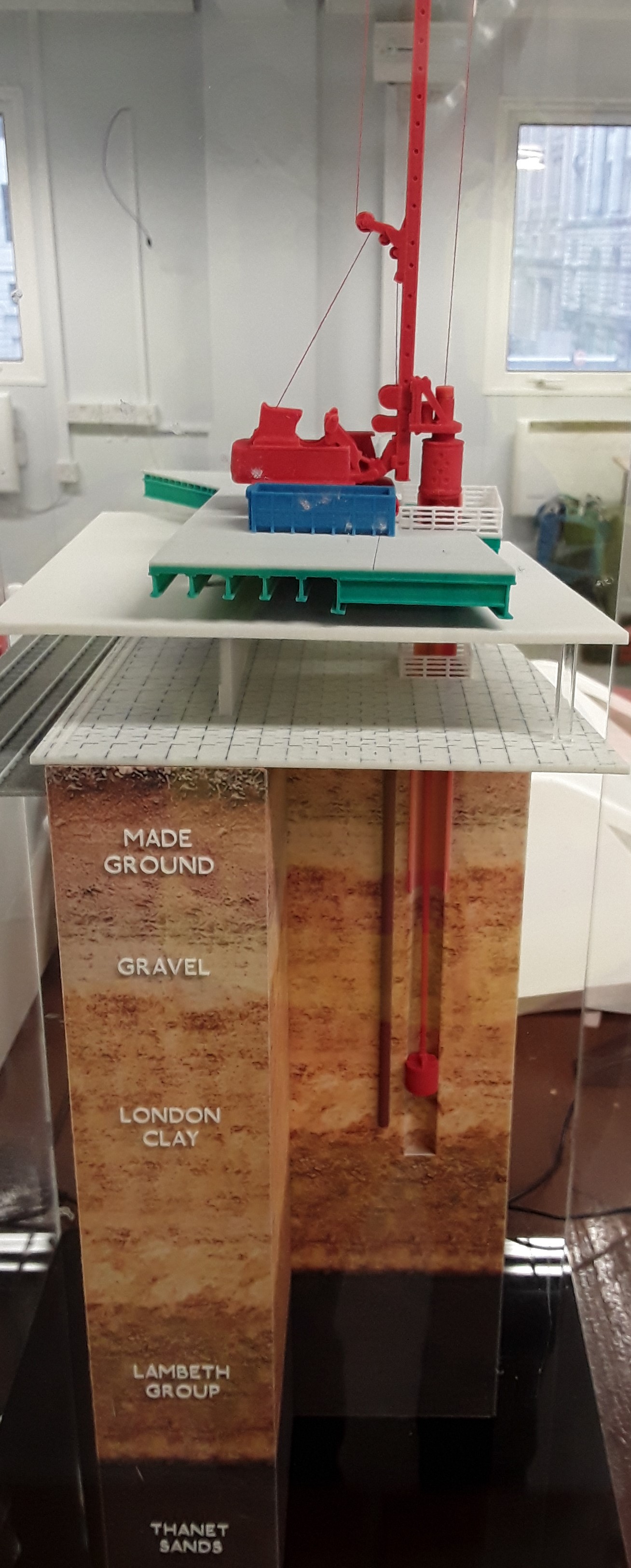
Piling model showing grillage, RD, rail platform, pile casing and soil strata
From this platform a steel casing was driven through the grillage, through the Moorgate platforms, through the made earth, through the gravel and into the London clay. The piles were then bored, from the grillage into the Lambeth beds, to depths of up to 57m.
The upper part of the pile acts a column through the station platform level and the casing remains in place. The piles are heavily reinforced in the upper sections in order to transfer moments imparted at the head by the base plate connections. The steel columns are fixed to the pile heads and tied into the reinforcing cage at the head.

Pile function
Moments are ultimately transferred by the piles to the ground beneath platform level as shown in the sketch above.
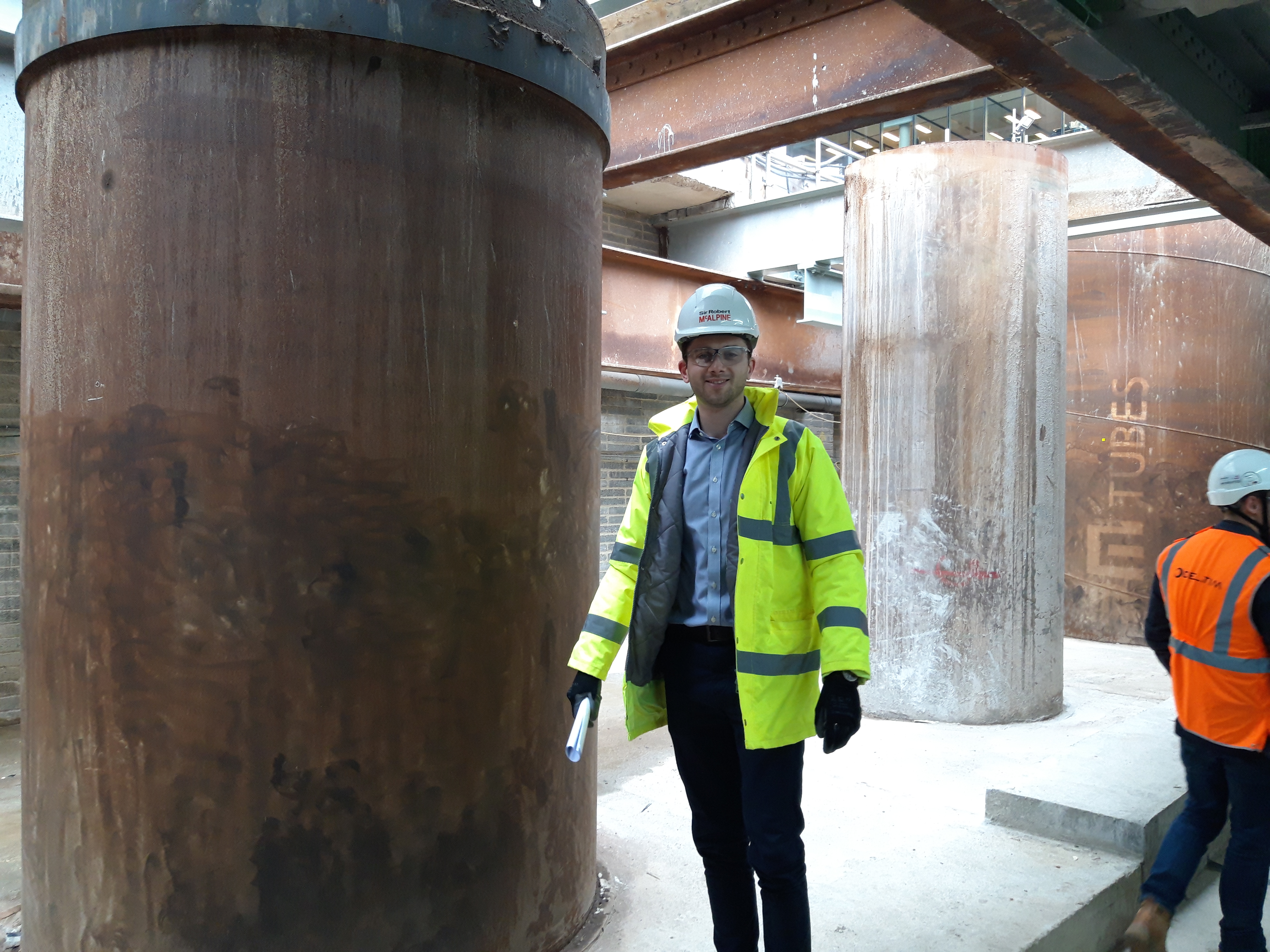
A smaller 1.8m diameter pile (with engineer for scale). Total 12 No 2.4m dia piles and 4 No 1.8m dia
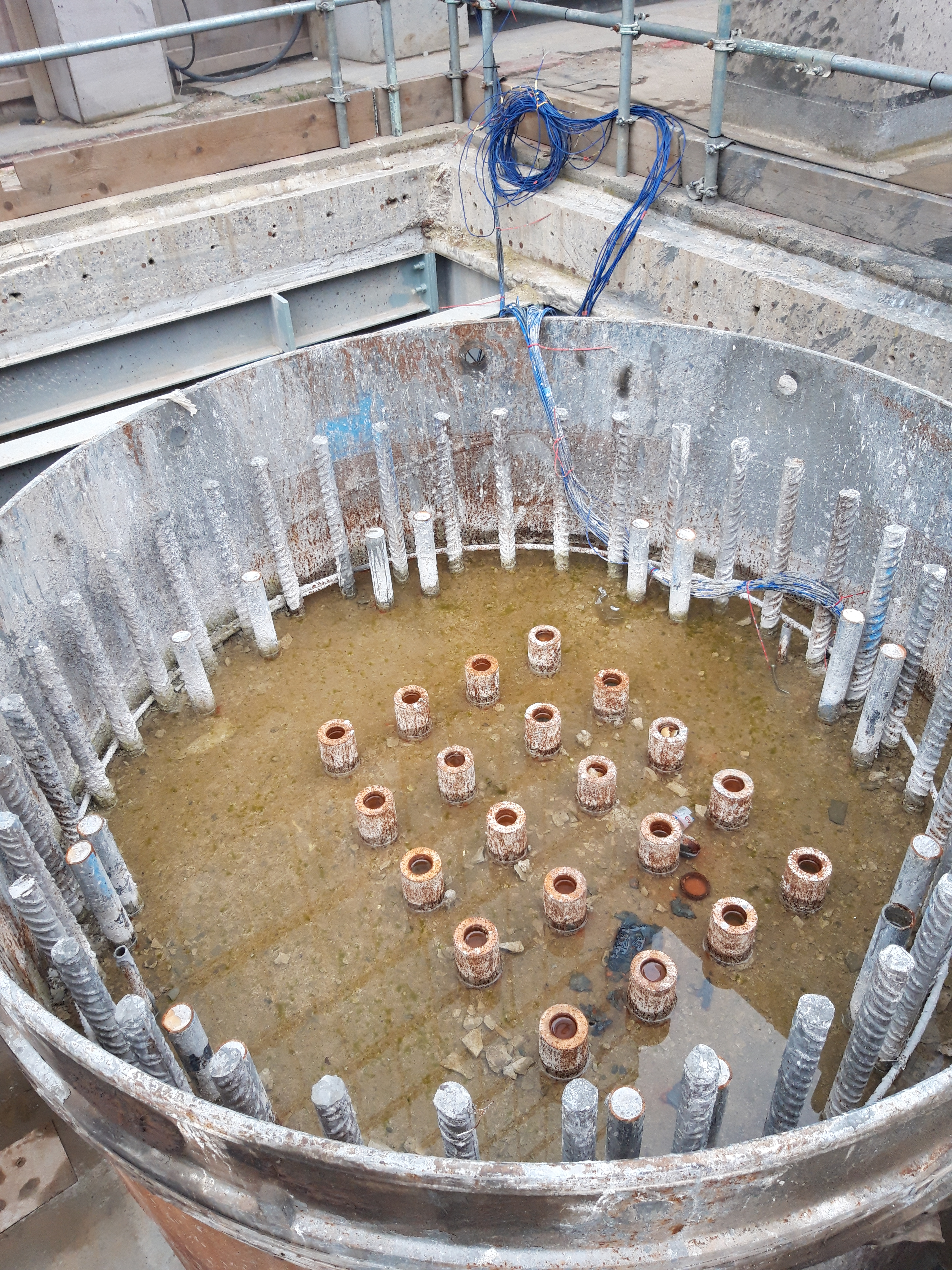
The piles have also been fitted with fibre optic strain gauges and grout tubes. The 5×4 anchor grid (seen below) was used to connect 4 No piles as reaction piles to the test rig for preliminary testing of a 1.2m pile. Axial design load on a 2.4m pile is 58MN.
Pile reinforcement (28 No H50 longitudinal bars with H16 links at 150mm centres), fibre optics and grout tubes.
Is this ground a risk?
I am currently sitting in a small team overlooking the demolition and then reconstruction of a car park in Woking.
The project manager has tasked me with setting the piling Matt levels to allow the piling contractor a flat even surface. We have decided on two piling Matt levels (ramp and car park) across the site with a battered edge between them to allow for the different ground slabs. The street level is approximately 28.5 to give an idea of how this will look on the ground.
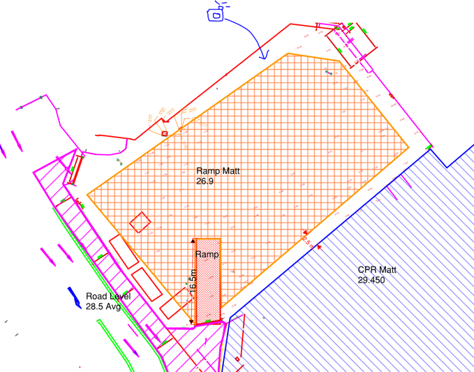
The ramp into the CPR cannot be seen on this drawing but does exist.
My main concern is with the level of the “Ramp Matt” which is adjacent to a Primark and Debenhams to the north and east. Looking at this problem it seems that we would be undermining the foundations of the existing buildings to excavate down to 26.9. Nobody seems to be able to tell me what foundations sit underneath Debenhams or provide any GI data beyond “it’s a clayey sand”. So it seems like an obvious answer, you need a retaining structure between Debenhams and the proposed piling Matt, but the plot thickens…
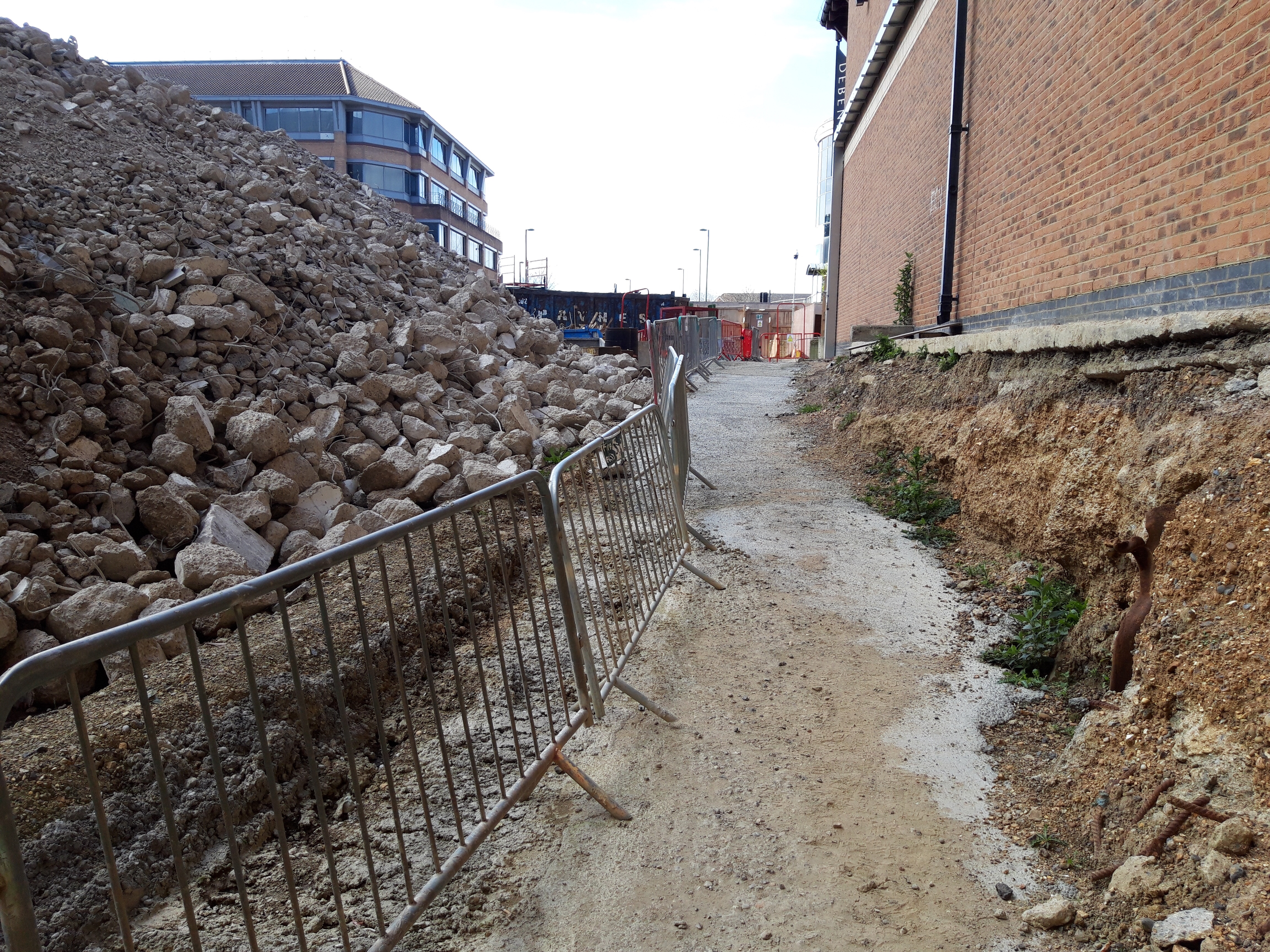
The ground has already been part excavated to allow access for workers and is standing freely. There is no evidence of the foundations under Debenhams and the ground seems to be holding. Supposedly this has been the case for the last 18 months. I asked who led with the initial excavation and it seems it was “just done”.
That photo is taken at the proposed level of the piling Matt but the ground rises into the far ground up to street level, the proposed Matt will remove that rise so the whole ground sits at the level the photo is taken at. It seems to me that the attitude is simply “it’s ok now so it’ll be ok to take the rest out” without anyone raising any alarm bells. Am I crazy or is this in need of an actual substantial design?
