Archive
How to pile through a railway station
As we aren’t able to add pictures to the replies, this is a quick post to answer Richard’s questions about the pile heads.
First things first – the time lapse camera looks west, from the ‘back’ of the site into the narrowest end. The view in my first blog An engineer without a site… for now. shows the remnants of a considerable amount of steel. This steel was formerly a piling grillage which can be made out below.

August 2018 – piling from the grillage at 21 Moorfields
The retained deck (RD),a composite steel beam and RC deck which is both the ground floor of this site and the roof of Moorgate station, is only rated for 10kPa UDLs so could not bear the weight of piling rigs. To get these rigs on site a grillage scheme was installed (3000T of steel – more impressive temporary works!) on plinths tied into hard-points on the RD.

Piling model showing grillage, RD, rail platform, pile casing and soil strata
From this platform a steel casing was driven through the grillage, through the Moorgate platforms, through the made earth, through the gravel and into the London clay. The piles were then bored, from the grillage into the Lambeth beds, to depths of up to 57m.
The upper part of the pile acts a column through the station platform level and the casing remains in place. The piles are heavily reinforced in the upper sections in order to transfer moments imparted at the head by the base plate connections. The steel columns are fixed to the pile heads and tied into the reinforcing cage at the head.

Pile function
Moments are ultimately transferred by the piles to the ground beneath platform level as shown in the sketch above.

A smaller 1.8m diameter pile (with engineer for scale). Total 12 No 2.4m dia piles and 4 No 1.8m dia
The piles have also been fitted with fibre optic strain gauges and grout tubes. The 5×4 anchor grid (seen below) was used to connect 4 No piles as reaction piles to the test rig for preliminary testing of a 1.2m pile. Axial design load on a 2.4m pile is 58MN.

Pile reinforcement (28 No H50 longitudinal bars with H16 links at 150mm centres), fibre optics and grout tubes.
Is this ground a risk?
I am currently sitting in a small team overlooking the demolition and then reconstruction of a car park in Woking.
The project manager has tasked me with setting the piling Matt levels to allow the piling contractor a flat even surface. We have decided on two piling Matt levels (ramp and car park) across the site with a battered edge between them to allow for the different ground slabs. The street level is approximately 28.5 to give an idea of how this will look on the ground.
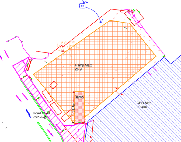
The ramp into the CPR cannot be seen on this drawing but does exist.
My main concern is with the level of the “Ramp Matt” which is adjacent to a Primark and Debenhams to the north and east. Looking at this problem it seems that we would be undermining the foundations of the existing buildings to excavate down to 26.9. Nobody seems to be able to tell me what foundations sit underneath Debenhams or provide any GI data beyond “it’s a clayey sand”. So it seems like an obvious answer, you need a retaining structure between Debenhams and the proposed piling Matt, but the plot thickens…
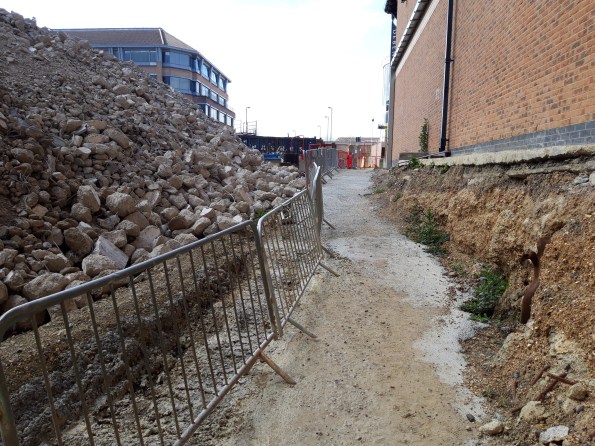
The ground has already been part excavated to allow access for workers and is standing freely. There is no evidence of the foundations under Debenhams and the ground seems to be holding. Supposedly this has been the case for the last 18 months. I asked who led with the initial excavation and it seems it was “just done”.
That photo is taken at the proposed level of the piling Matt but the ground rises into the far ground up to street level, the proposed Matt will remove that rise so the whole ground sits at the level the photo is taken at. It seems to me that the attitude is simply “it’s ok now so it’ll be ok to take the rest out” without anyone raising any alarm bells. Am I crazy or is this in need of an actual substantial design?
