Bye Bye Tolerances
Yesterday on site we had an interesting discussion about an issue which has been in the background for a while, which everyone has been ignoring until it’s actually preventing concrete being laid.
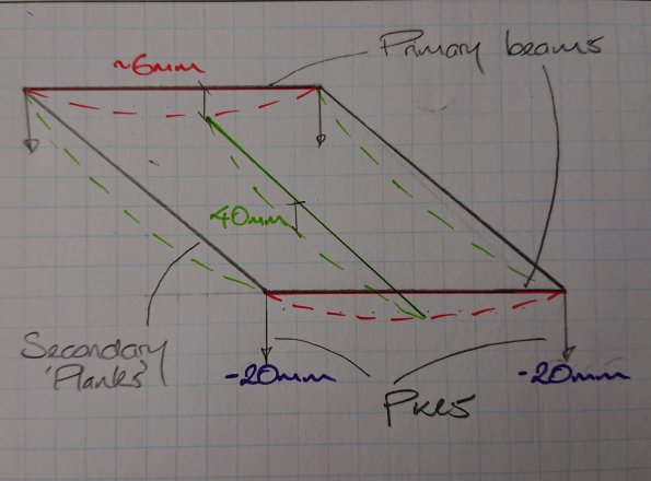
Issue: The pavement thickness of the client has been specified as 150mm + 20mm. The precast secondary elements they are resting on are designed to deflect up to 40mm, the primary beams 6mm and the piles to settle up to 20mm. Whilst we haven’t actually been given FPLs (finished pavement level) by the designer yet, they are coming and we will have to be within +/-6mm to be compliant with the spec.
This is a similar problem to on Joe Murrows site, we can’t however back prop to limit deflection as it is over water!
This has raised the following questions:
- At which point does out liability end? FPL which change over time therefore so long as it’s less than 20mm is that okay?
- We have raised RFIs regarding which is the overriding factor, pavement thickness or FPL. We think it is going to be FPL, but if it is do we risk overloading the planks to get this? Atkins have designed for the concrete to be up to 45mm thicker to account for this, it is likely to be tight at midspan though…. This also doesn’t take into account the as built levels being lower that design.
- How do we monitor this settlement?
- Currently we are monitoring the levels at the four stages highlighted below. What we have suggested is that monitor selected areas, these include areas under the most loading and where the piles might be bearing on different boundarys to those it was designed for. These are being monitored weekly at top of plank level, point 3.
- At the moment it all comes down to resources, it is isn’t in the spec that we have to monitor it, therefore there is no money for it. A very shortsighted viewpoint I think as the elements listed below are intrinsically linked to knowing how much movement there is!
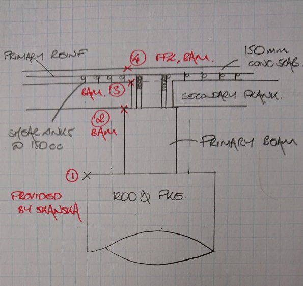
Areas where we are recording levels
Any ideas on how we could:
1. Cheaply and easily monitor settlement accurately?
2. Accurately measure Deflection?

It is not immediately apparent that there is a contradiction in this because the client might reasonably specify some construction tolerances for certain elements and a finished pavement level without necessarily compromising themselves. It is up to the contractor to determine the appropriate construction methodology that ultimately delivers the product and this might involve any number of techniques such as pre-cambering. It does, however read that BAM have started to build something without having the information that they need to know what it is they are building and in doing so might have put something in place that is not going to allow them to meet both the construction tolerances and finished levels. There is, within this, a potentially interesting / embarrassing cock up.
Another aspect to consider is the conditions under which the deflections and displacements you cite are expected to arise. Bear in mind that you are casting the topping on a composite slab, you are unlikely to experience the maximum working load tolerance deflection when casting and thereafter you will have a stiffer element.
I’d be wanting to check the Skanska levels marked (1) to make sure that blame goes in the right direction if their pile design is inadequate. I also suspect that, if they thought this might ever be an issue and was being measured, they’d design so that their tolerance is never at risk.
Having thought about it, I am not overly surprised that the specification does not require BAM to check levels during construction. That is their choice, they will be hanged for not meeting final levels at handover. It would be a very unwise contractor that didn’t feel a need to know what was being delivered at each step along the way. BAM’s risk, BAM’s cost.
Assuming pavement level is the specified product (along with deflection and numerous other aspects), and, given that there will be some movement over the life of the structure, how is this expressed in the contract and what measurement method is specified. This might give some insight into how the client will agree acceptance or otherwise and performance thereafter.
We measured deflection in a different area to my example you reference above using a 3D scanner – very fast but specialist kit brought in by the company’s head surveyor.
We continued to add concrete structural elements to a frame supported by rubber bearings – the more weight, the more they squashed.
In the deflection on metal decks that was a site engineer taking regular readings of fixed retro targets.
Have just replied to Tom’s comment with the below. Worth a quick sensitivity check to understand how much you can over-pour with a given geometry and stiffness of beams. If you are deficient then increase E or I.
“Try rearranging the deflection equation to see if you have adequate sectional geometry to handle the maximum allowable. In my case, the secondary beams had insufficient ‘I’ in the intermediate state.
eg.
δ = L/250 = 5wL^4 / 384EI
Rearrange for I (required).
Try this crib sheet for steel: https://htstrial.files.wordpress.com/2019/04/deflection.pdf “
Of the first ..I assume the problem is in accessibility; on piles …or in geotechnics levels are extended to the surface using invar rods…but that might not work here
On flexural things you can infer the deformation by using bonded or VWS gauges
Of the overall problem
1 The out-turn pavement deformation seems to come form standard highway practice. Might be harsh in this context. If you aid that the concreted deck was equivalent to the base course , then on shore would be specifying +_ 15mm Which seems far more sensible the concreted deck the final running surface or is there to be a surfacing course?
2 If I assume that the mean levels of everything can be brought to 0mm from the true ( so all the flexural things would have to be pre-cambered to the same extent as the predicted settlement) and then I model that 65% of it all ( each component result) will be +- 2mm from true ( ie one std deviation = 2mm) then I run a simulation on this… I get an 85% chance that you could be within +- 6mm on out-turn
(I get greater than 99% will be +_15mm)
So in English ….with very tight pre-camber and very tight site control you can expect 15% of the pavement won’t be within out-turn spec
Since the only thing you can measure is the out-turn level AND the only thing you may be able to finally control is the final topping, then the issue might be looking at the probability up to the surfacing level and then looking at the extent to which there would be a balance in adding surfacing and causing greater surface deflection