How to put overweight building design on a diet?
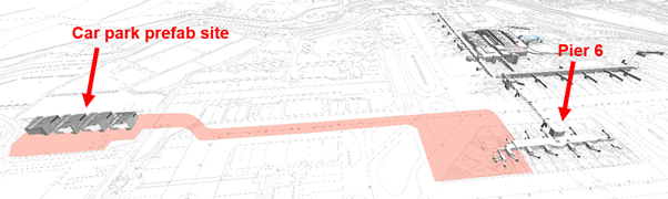
The largest project at Gatwick ongoing at the moment is the western extension to Pier 6 at the North Terminal. The project is currently at RIBA 3 (developed design) stage. In order to mitigate the impact to aircraft operations, the construction method involves building a steel structure from four separate modules off-site at a car park. It is intended that as much of the construction work is prefabricated here before the modules being moved on Self-Propelled Modular Transporters (SPMTs) across the airport to connect to the existing Pier 6 building (see Figure 1). I understand that something like this, where the whole module will be fitted out off site, has not been done before, therefore brings with it some interesting challenges.
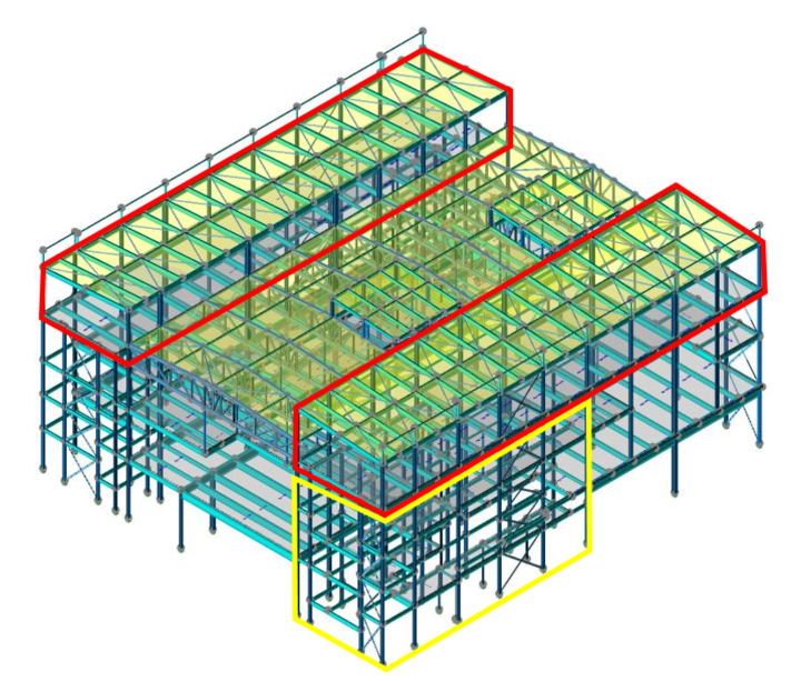
The original module design can be seen in Figure 2 below. One of the biggest problems that has developed during the design stage has been the addition to the original module design of a significant amount of steel (1000 tons +!)[. This has largely come about due to a number of factors, one of the most significant being the key stakeholders changing their requirements part way through the project. This has meant that larger Vertical Circulation Cores (VCCs) are required, increasing the steel required for the modules.
The revised design (see Figure 3) has seen the plant rooms on the roof reduced and the overall structural design simplified. Because of this simplification, larger columns and beams are now required, increasing the permanent loads despite the reduction of the plant rooms. I understand that the design was simplified for better buildability and easier ability to move by SPMT.
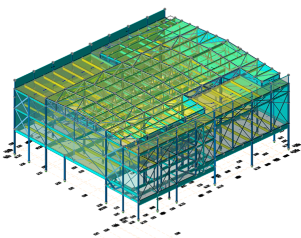
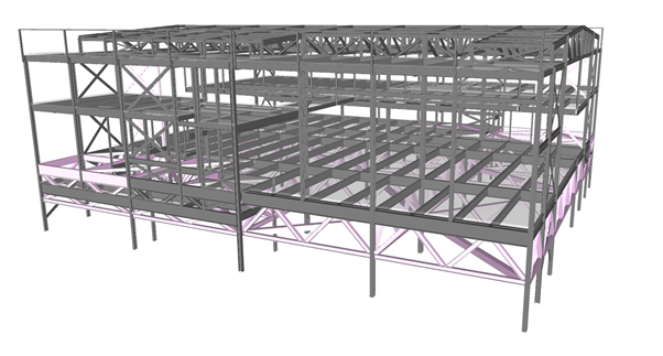
Additional temporary steel has also been required due to the need to keep the structure as rigid as possible during the SPMT move across the airfield. This has added a significant cost on top of the forecasted costs originally envisaged. Note in figure 3 that there is a lot of temporary cross-bracing to keep the structure rigid during the SPMT move. The cross bracing would prevent lateral movement though I believe it would not overcome torsional effects of the SPMT move, i.e. it would twist. Figure 4 shows a potential solution where the building sits on a truss. This uses more steel than the other design but allows the building to transfer loads much more effectively to the SPMTs.
Gatwick are negotiating with the designer on further compromises to this issue. The structural designer has added up to a 15% addition of steel to their calculations for connection detailing and 10% for ‘contingency allowance’. I’m not clear how they have come to these figures but do they seem right?
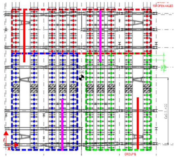
The modules also do not impose a uniform load, with the VCC part of the structure imposing more load than other areas. To mitigate this the SPMTs have been arranged in groups of three (see figure 5 below), much like the point support of a three legged wooden stool. Interestingly the module loading is distributed into four quadrants and it was originally suggested that the SPMTs also be grouped likewise. However, the SPMT contractor has stated that a four group method is not preferred due to additional control complexity during transportation.
All of this makes me wonder whether this method of construction, whilst quite innovative, has come with additional (expensive) obstacles. It may have been more economic to build the pier on site, with most of the work being done during operational stand-down hours at night. This however may have added additional time to the project. I look forward to seeing how this project evolves in the future.

A few questions really; you say earlier that there are four modules but Figure 5 shows 3 ?
What is the mass of a module and how is it intended that they are moved?
The point about contingencies; these models are something like Tekla structures and these tools are expected to provide QS function.. so that , barring site wastage, they measure quantities precisely. So the need to 10% plus for connections starts to look ‘old hat’
The weight of a module is somewhere in the region of 1400 tonnes (including temporary steel). There are indeed four modules and they are being moved individually. Figure 5 shows 10 rows of SPMTs (Video of what an SPMT is here: https://www.youtube.com/watch?v=6d4tBG31uvo) that move one of these modules. Each module is about 50m x 50m so that gives you an idea of why so many are required for the lift. In order to control the move the loading is controlled in three areas highlighted by the colours.
Presuming the structure will be deemed to be in a safe location once constructed, one has to wonder if there isn’t a little bit of excess caution in terms of needing to complete all work during night closures. I would have thought a sensible hoarding line with delivery during closure and thereafter construction shouldn’t be an issue. But then I’m not a nervous airport operating authority that doesn’t understand construction. Are these modules being completely clad and fitted out before being moved onto site?
I’d say that this is a good example of designing a structure for all stages of its lifecycle including construction, which is evidently the worst case for stability.
The design is trying to achieve as much of the construction off site as possible. Therefore most of the cladding is to be installed off site. However, the current design has 4m of blockwork on the ground floor that will clearly be constructed on site (each module is about 20m high). There are also a number of E&M items such as escalators that will be installed on site too. So not quite all prefab; though seems to me that it would be impossible to achieve a purely prefab build on this scale anyway.
OK, put more bluntly what is driving the ‘offsite’ construction concept? It has the smell of being a ‘good idea’ decided upon without a proper understanding of the implications. It doesn’t appear to have consistency of rationale and, as Glynn observes, might not stand scrutiny if revaluated now.
Hi Al, an interesting read. Sounds like a “has the situation changed?” moment. I would have thought that this method only provides a benefit for a very specific set of parameters and probably, as you identify, why it has never been done before. Sounds as if the Clients design changes and re-design are pushing the boundaries of these benefit parameters? I have noticed a couple of times during my phase 3 placement that there is a communication breakdown between what designers believe is the preferred method of construction (and blindly use these constraints to formulate their design) only to present a design to the construction contractor and the ‘goal posts’ for the method move. These changes aren’t as complex (or costly) as your problem, but early communication seems to be the key.