When things don’t go to plan… engineer your way out of trouble!
Over the last few weeks we have experienced a number of issues on site. For those who missed my first post, I am working on a bridge replacement project in Australia. My current job is working with the team to establish the precast yard for segment production. This post covers the main problems encountered so far and how we are engineering our way out of trouble…
- Design. The precast yard is essentially temporary works on a large scale. To maximise profit, the contractor spent limited time and money as possible on the consultant design. The result was independent design teams working on the earthworks, drainage, structural design and environmental plans. This approach could have worked however, no attempt was made to overlay and combine the designs. Needless to say there have been a number of oversights which have only been identified on site during construction. This issue has been compounded by a lack of access to CAD drawing files on site (and project level) and a lack of setting out information on the drawings. This has resulted in issues with the earthworks and drainage across site.
Lesson Identified: saving cost on design = additional cost in execution.
- Earthworks. A GPS grader was chosen to perform the majority of the earthworks due to ground conditions and speed, resulting in cost savings but has not proven to be the case. The grader was used to cut/determine the majority of levels on site. Although the technology is pretty accurate (verified by an on-site surveyor), the machine is only as good as earthwork model provided. Due to design constraints, the model was oversimplified and contained a number of errors. The result has been a lot of repeated work and significant overspend on earthworks. We are now using a surveyor to set out and confirm the remaining earthwork levels which is an additional cost.
Lessons Identified: (1) Technology is great when resourced correctly. (2) Always check levels with a surveyor.
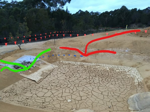
- Drainage (1). As alluded to earlier, the precast yard design has not been completely coherent. An example of this is the drainage ditch along the eastern boundary of the site. The ditch is shown in different locations on the stormwater and environmental plans (without setting out data) and is omitted completely from the site GA dwg. The ditch was initially constructed as shown on the environmental plan (alignment marked red in picture below) but was later identified during an as-built survey as being upto 10m into the segment storage area. This effectively halved the precast yard segment storage capacity and was considered unworkable. The solution was to move the ditch onto the site boundary (alignment marked in green) and spend even more money on earthworks!

For those with a keen eye, the embankment near the trees is well in excess of the approved design batter (45 degrees). I anticipated this and highlighted my concerns to the Superintendent and Precast PM prior to moving the ditch. The PM (a chartered Australian Civil Engineer) shared my concerns but it was decided to proceed. If required Superintendent agreed to stabilise (or potentially shotcrete) the slope later if necessary but nothing will be done initially to save money. I’m interested to see how the slope copes during the next period of heavy rain.
Lessons Identified: (1) If it doesn’t feel right trust your instincts. (2) As-built surveys can help identify issues early before they become a big problem (or nightmare to fix later).
- Drainage (2). During the early earthwork stages, one Supervisor decided to go a little ‘off plan’ and decided to connect a sedimentation pond at the northeastern corner of the site with the eastern ditch (shown above). This would remove the need for the sedimentation pond and allow free drainage around the site to a larger off-site sedimentation pond. Although a good idea in principle, after some extensive earthworks to connect the two features, it was realised that the Supervisor had failed to check the required levels. The picture below shows the eastern ditch highlighted in red and the north ‘overflow’ channel in green. The overflow outlet level is approximately 500mm lower than the eastern drainage ditch outlet. To work as the Supervisor intended the entire eastern ditch would need to be dug lower. Due to the earthworks overspend and slope stability issues this won’t happen.
Lesson Identified: Don’t cuff it, double check it.
- Piling. Due to the weight of the segments, deep foundations are required for the segment mould casting area. The solution was 52 No. 350mm square precast piles with predicted toe depths varying between 6.5m and 13.0m. Having only seen videos of piling I was excited to see live piling in action so made sure I had a good view for the first drive. The left-hand picture was taken after the first two piles had refused early at approximately 6m and 4m above the intended toe depth. The piling team started ‘sucking teeth’ over the more difficult than expected driving conditions which started a mild panic in the project team as the contract cost of pile ‘break-back’ per meter was going to cost a fortune. As briefed during the Retaining Soils module the piling crew left the piles to settle for over 24 hours and attempted to re-drive with an increased hammer weight. The right-hand picture shows a photograph of the piles at the end of driving. The good news was the first two piles were driven further (up to 3m); the bad news was that a number of piles were significantly proud. After searching for ‘experienced-wisdom’ and seeking advice from the piling sub-contractor, a method was devised to cut-off the excessively proud piles to reduce the amount of ‘break-back’ required. Pile Driving Analyser (PDA) tests were conducted on 5 piles which indicate the piles have an ultimate geotechnical capacity in excess of that required.


Lessons identified: (1) Don’t panic too soon. (2) The amount a pile can still be driven following an initial refusal is surprising.
- Reinforced Concrete Foundation Pour. This week we started the foundation pours. The first pour of 167m3 went relatively smoothly however the second 310m3 pour was slightly more dramatic. With pressure on to complete the pour as planned so the concreters could fly home for Easter and the steel erection team could start straight after Easter a big push was required. We initially made good progress and placed 200m3 before the sub-contractor’s concrete boom pump malfunctioned. For safety reasons, the Superintendent immediately prevented further use of the boom pump and instructed for the remaining section of the pour to be completed from the back of the cement mixers. There was no standby boom pump on site and as Batemans Bay is a small coastal town so there was no hope of getting a replacement at short notice. Due to site constraints, the remaining 100m3 in the next pour section wasn’t accessible by cement mixer so the rest of the pour had to be postponed. This initiated a chain reaction of phone calls between the batching plant, boom pump hire company, concreters and sub-contractors to rearrange for the next day. The biggest immediate problem was the 10m3 of concrete already on site that would be in excess of the completed section. We rapidly made plans to use some of the concrete as blinding for subsequent foundation pours however over 7m3 of concrete was wasted as alternative pour locations were not ready.
Lesson Identified: Always prepare an alternative pour location for excess concrete disposal.
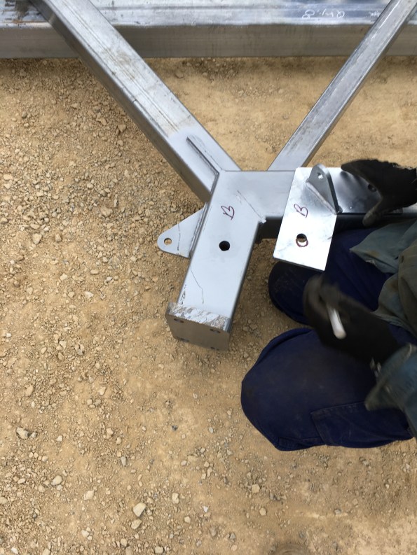
- Steel bracket fabrication. We have also been having issues with the steel frame provided by the fabricator. Their deliveries have been fairly hit and miss and not in a logical sequence to facilitate erection from one end of the structure. With the steel erectors on site this week we identified that all the plates supplied have incorrect bolt holes with each plate requiring a different remedy (picture below illustrates where the bolt hole should be). Due to the Easter and ANZAC Day public holidays, it would take two weeks to get the plates fabricated correctly. With hefty liquidated damages (LDs) for any components not on site before 26 Apr, the Superintendent brokered a deal between the steel fabricator and our steel erectors to adapt the plates on site and keep the steel erection on track. The steel erectors have conducted ground level on-site pre-fabrication this week as we are still awaiting delivery of key bracing components before the structure can be erected. With one delivery expected tomorrow (26 Apr) it will be interesting to see which items are on site before the cutoff and how the LDs work out. The good news is tomorrow I have to account for all the steel held on site – and I thought weapon serial checks were on hold for the next 18 months…
Lesson Identified: It’s the little things that stop the big things from happening…

Nice Update! I’m interested to learn more about the GPS grader experience and potentially pass information to the MPF contingent here. I take slight issue with the Drainage 2 piece because it doesn’t matte r that the inflow ditch discharges above the overflow lip as long as it discharges into a pond with sufficient capacity before the overflow level is reached. In accounting for steel held on sit you presumably only accent that which is within specification and thereby might be forced to work counter to any localised deal that is outside the contract. I look forward to the next instalment!
All interesting
Some of these, expanded a bit look like they might make useful TMR material
I would say this wouldn’t I …but what were the piles being driven into and why had the bearing /skin friction been so underestimated?
IF redrive worked ( a bit) it might suggest dilation during the drive – so a coarse grained but at the fine end and below he gwl?
I am struggling to find the geotechnical report that influenced the pile design however, I have found the geotechnical report for the design of a piling mattress and crane platform at the same site based upon borehole data.
The report states ‘Five boreholes were drilled to depths of between 3.0m and 30.0m. Ground conditions at the site typically comprise interbedded layers of silty sand, gravelly sand and clean sand, with uncorrected SPT “N” values ranging from 17 to 49. Occasional SPT refusal occurred below 12m, but it is unclear whether this is due to a hard/cemented layer or the presence of coarse gravels.’ The borehole lo shows CLAYEY SAND to 0.5m below ground level followed by GRAVELLY SAND. The geotechnical design report continued to state that strength properties were calculated assuming a standing groundwater table at no higher than 10m below ground level and an assumed bulk unit weight of 18 kN/m3.’ A design ‘in-situ’ angle of internal friction (phi’) of 40 degrees was interpreted from the test results for foundation design despite the majority of plotted results falling between 45 and 50 degrees.
CBR measurements were also taken with CBR values between 3 and 60% observed. A design CBR of 8% assumed by the geotechnical consultant. Interestingly the report links the variation in CBR values to potential weaker layers of clayey material of up to 0.5m thick.
I am speculating here but I think the bearing/skin friction was underestimated due to the combination of underestimating the in-situ strength of the soil (due to clayey deposits and an engineering safety factors), an incorrect assessment of the groundwater level and adding ‘P for plenty’ into the pile capacity design.
Please let me know if you would like me to email you a copy of the GDR I have access to along with the pile design and pile driving analyser reports.