Archive
Gatwick concrete cracks
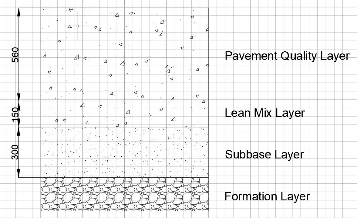
As part of the A380 stand upgrade works ongoing, the aircraft taxiway pavement is being upgraded to support the heavier loads of the A380. The pavement is of a ‘rigid’ design and has been constructed in three layers (see Figure 1): a granular subbase (300mm) with Lean mix concrete layer (150mm) with a specific Pavement Quality (PQ) mix layer (560mm). There is no reinforcement to the pavement quality layer as I understand it is assumed the concrete will be working in compression only. The concrete for the new stand is being built in sections, with one of the longest sections cast recently. This section was cast 30m in length total by 5.5m widths and then cut into 6 parts for movement joints.
It was discovered recently that a substantial crack had developed through the thickness of the PQ layer at this section. The crack is highlighted in Figure 2 below.
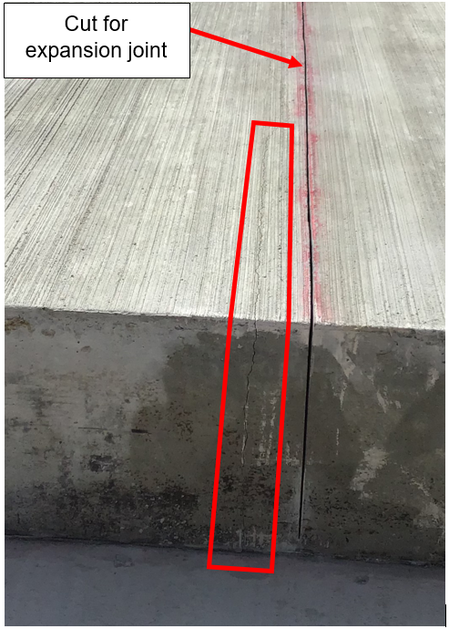
It is thought on site that the crack sits over a hard area of ground and may have formed a crack where the concrete was acting in tension. As the crack is close to the cut for the expansion joint it may be possible that the contractor waited too long before cutting the joint, resulting in the crack.
It is likely that this PQ layer will have to be broken out and cast again, as water ingress into this crack will cause future problems. The crack may have been avoided by casting the blocks in smaller sections, reducing the tension on the PQ. I would be interested to know any thoughts on this problem and any ways in which it might be resolved. Such an issue will no doubt be costly for the ground works subcontractor.
Structural clash detection using 3D modelling and point cloud survey
One of the less helpful outcomes of the acrimonious handover of my site from Mace to McAlpine has proven to be the lack of accurate site condition data. Without the ability to survey the site before taking possession we have been left playing catch up on a number of important issues.
The 14 large-diameter bored piles, installed by Mace, are to receive base plates with pre-fabricated column starters and reinforcement cages. These units are limited in size by the capacity of our tower cranes but still come in at up to 18T per piece. This single unit is then to be lifted into place within the pile casing without clashing with any of the existing pile reinforcement. The plan is then to top up the concrete/grout beneath the base plate. The many risks in process can wait for another time because the first problem came with the site handover.
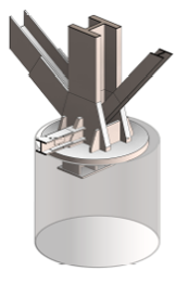
Revit model of the column base plate in the pile casing
On inspection of the pile heads the existing reinforcement on one of the piles was visibly wonky (technical term). This raised concerns over the global positioning of the pile, was it the rebar or the pile sleeve that was wonky, what is the design tolerance for position and verticality, which was in the right position, who surveyed it for the as-builts and how, etc, etc but the key question was simply can we get the base plate in in the right place without clashing with what is already there.
Having satisfied ourselves that the base plate would fit inside the pile sleeve we set out to identify any clashes with the rebar. In collusion with our geospacial team and BIM manager we superimposed the structural model onto a point cloud survey and ran clash detection between the two. This quickly showed the extent of our problems and has allowed for mitigation measures.
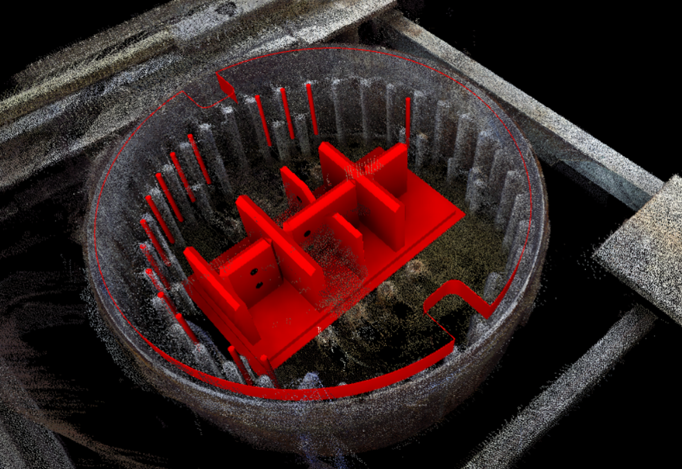
Model vs point cloud clash detection, red indicating clashes.
Of the clashes, in red on the image above, some could be removed on site (e.g. the anchors you can make out beneath the main steel shear key plates were cut down) but there was to be no damage to any of the existing pile reinforcement (the outer ring of vertical H50 bar, in grey on the image). Instead the structural engineer instructed that the base plate be re-worked off-site by cutting and re-welding the base re-bar.
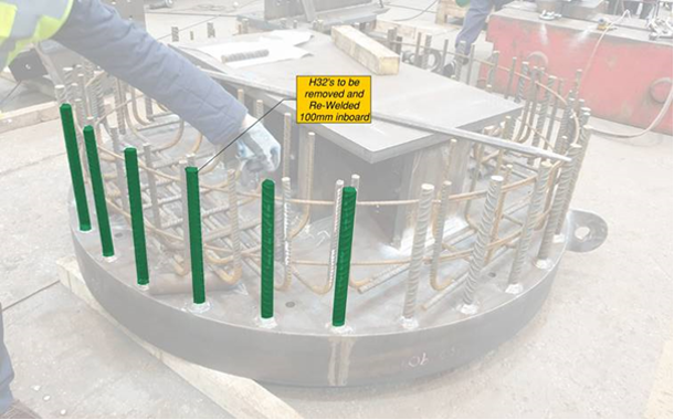
Diagram showing base plate rebar to be cut and move inboard to avoid clashes.
This use of 3D modelling and clash detection software was able to identify a serious clash before the key components were delivered to site. Being as the fabricator is in Bury and the work required could not be easily done on site, this early notification prevented an expensive, time consuming and awkward clash on site.
Rebar Near Miss
I thought I would share a near miss that could have ended very badly on my site last week. It is still currently under investigation so this information is as accurate as I have it at the moment but is still a little sensitive.
The demolition of the car park is about 70% complete and we are working approximately only 10-15 metres above street level. At the time of the incident we were on floor 2 demolishing a beam and column on the leading edge of a cantilevered section.
The procedure had been always to break the cantilever from the top completely, clear the rubble and then move the plant backwards a structural bay and start on the main slab. As the slab is much thinner than the beam of the cantilever the machines normally leave the beams until last. A 13t excavator will break the concrete off the beam and then use its arm to bend the rebar downwards so it is not protruding. A worker with a gas cutter will then follow behind and trim this bar.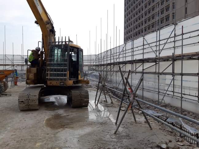
On this particular day the job was assigned to a new driver who in turn was using an 8t breaker which did not have the power to bend the rebar with its arm. The driver after breaking out the concrete could not bend the bar and instead of waiting for the bar to be bent by someone else just continued the job. He began breaking the top of the concrete column the beam was fixed to. This lead to the loosening of the protruding rebar and eventually it became dislodged and fell from its position, through the scaffolding onto the street below. 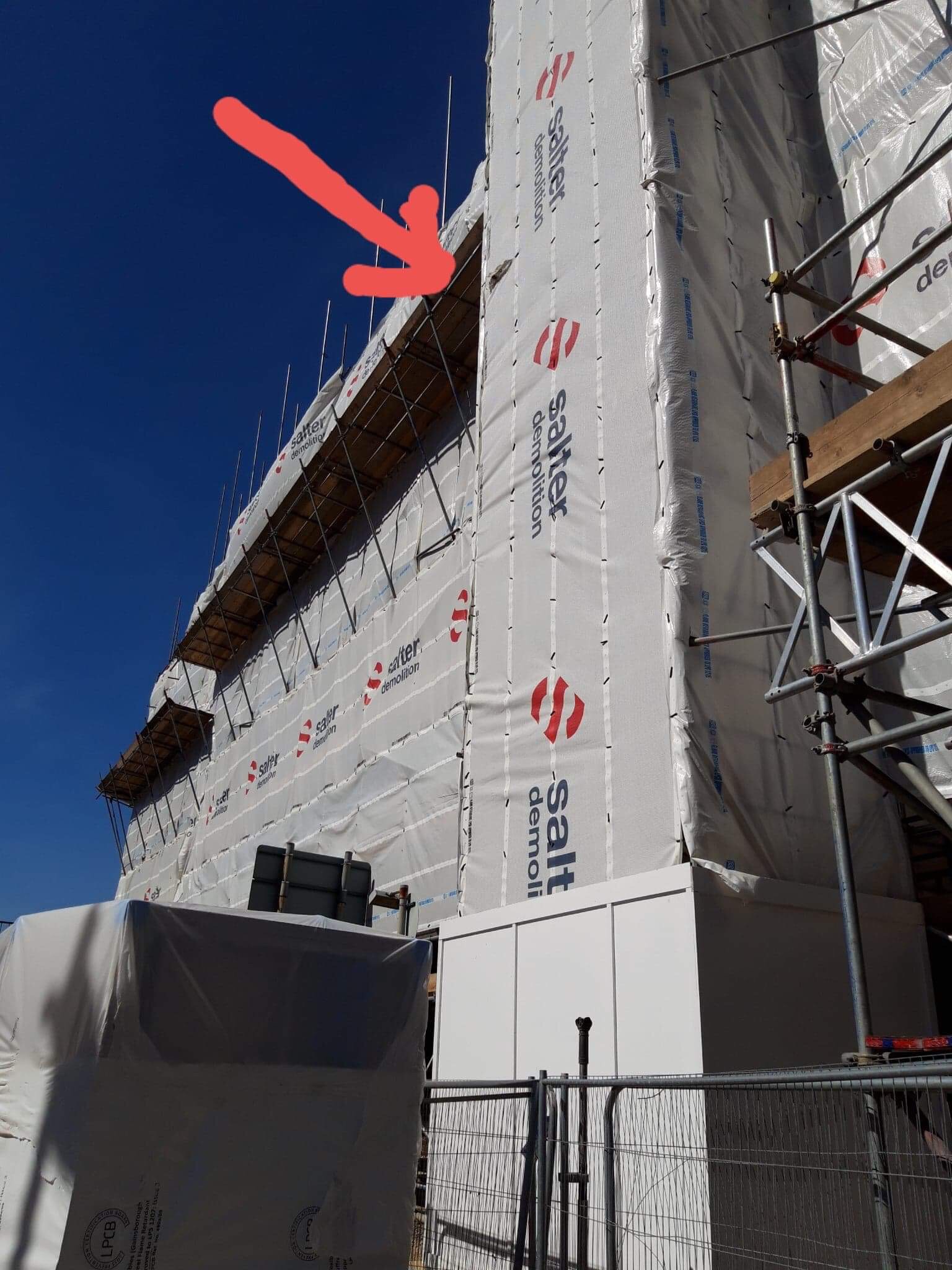 This photo shows where the rebar fell from the staircase and the pod it hit below
This was 5m of 32mm bar weighing approximately 30kg. It landed on a bathroom pod that was being delivered at the time and skewered it straight through writing the pod off. It goes without saying that had the delivery not been taking place it is just as likely a person could have been stood in the exact position. 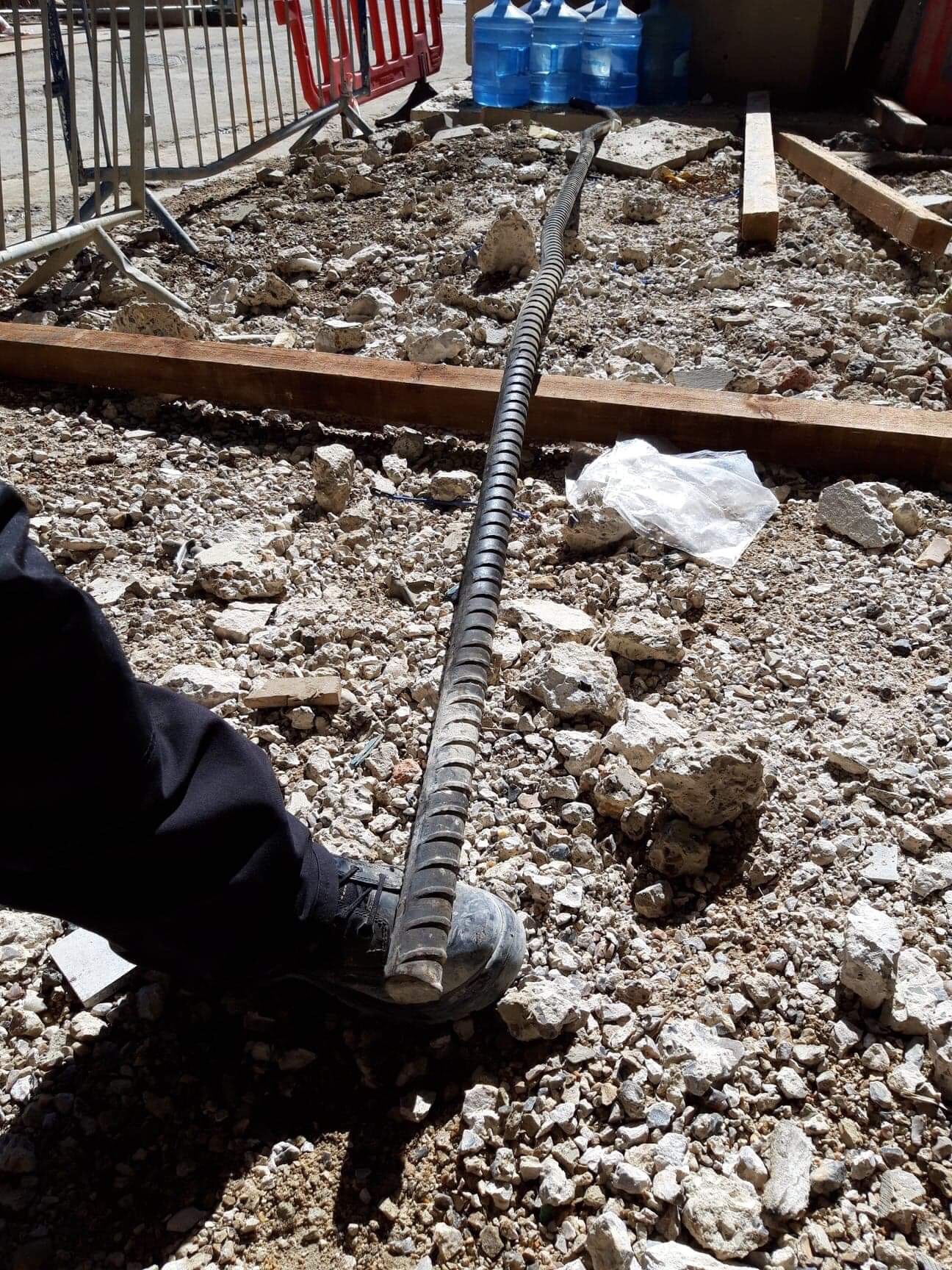 This is the offending bit of rebar. My foot for scale (size 9)
Conclusion: The machine operative was sacked that day. The method statement has subsequently been re-written now that when attacking columns with cantilever rebar still attached it must be attacked from the bottom and once the concrete is removed the whole column may be bent down by a 13t only. This previously was not done because of the risk of the larger structure falling onto the floor and causing collapse of the slab with the machine still on top. To prevent this the machine must reverse a structural bay back before pulling the beam down. 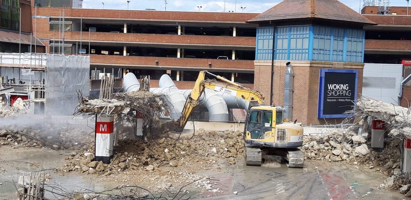 This photo is the new method of leaving some concrete above to keep the rebar secured and then break the bottom of the column.
I have tried my best to explain the procedure but I have attached photos that hopefully paint the picture.
I must say relationships before the incident were of mutual trust and SRM were happy to let the subbie a little slack, since the incident SRM have tightened the lead a little and it is leading to tension on site. The subbie maintain it was a “freak accident” but then why would they sack the operator? SRM monitor and grade their SC on a monthly basis and that goes into a central company tender database – something tells me this subbie may not be selected again.
Bridge over troubling roofs (Part 1)
Hello all, the Pier 6 extension at Gatwick is still going through the RIBA 3 design stage so I thought I’d switch fire to another project in the pipeline. The International Departure Lounge (IDL) link bridge is due to be built at Gatwick in the third quarter this year. It is still in the RIBA 4 design stage with the awarded works contractors now looking at the detailed design. The purpose of the bridge is to provide a more direct route between the new code F site at Pier 5 (see my first blog post) and the departure lounge. In short it is intended to improve passenger flow to the new A380 aircraft stand. At the moment passengers have to walk an indirect route to access the Pier 5 stands which adds additional walking time, reducing flow.
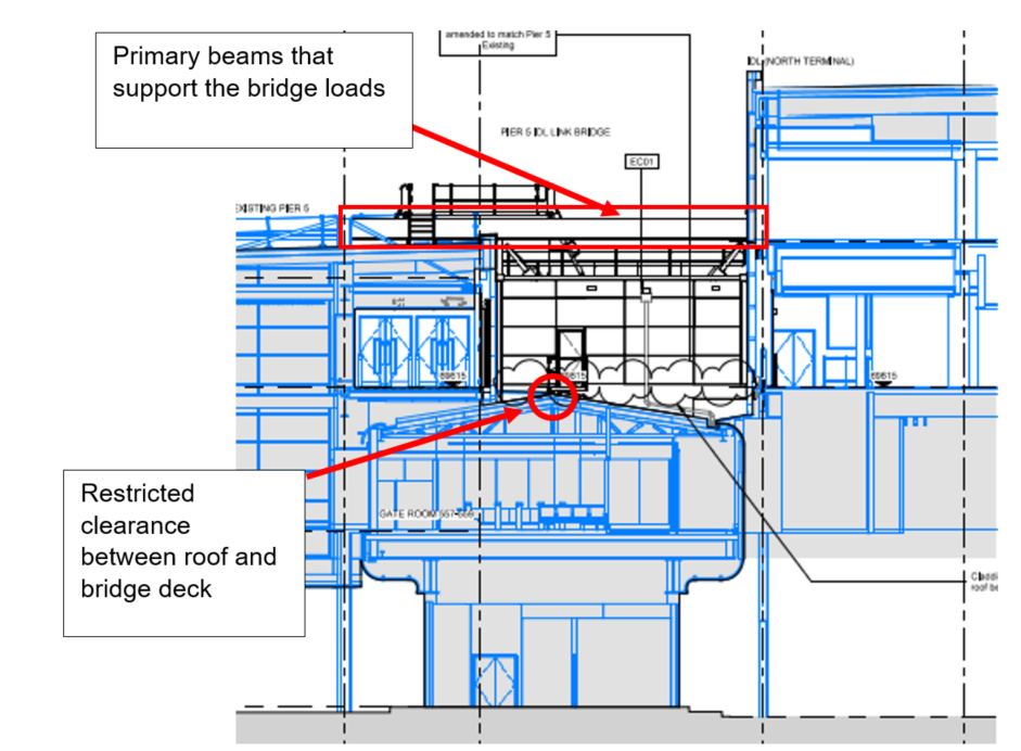
The construction of the bridge presents some interesting challenges as it is to be located in a heavily built up part of the airport. As can be seen in Figure 1 below, the location of the bridge is difficult to access for plant and equipment. Crane access is also difficult due to the size of the existing buildings, limiting prefabrication options. Therefore the building is to be stick built to account for the congested site.

The proposed design can be seen in Figure 2 below. Due to the level of the bridge deck and the roof structure of the building underneath, the clearance of the top of decking and the top of the roof ridge is approx. 200mm. This has dictated the size of the beams that support the deck as can be seen in Figure 3 further on. This means that a traditional bridge structure where the deck beams are supported below is not feasible. The design therefore transfers the bridge loads from the deck through columns attached to two beams located above the bridge corridor. These connect to beams that span between the columns of the existing buildings.
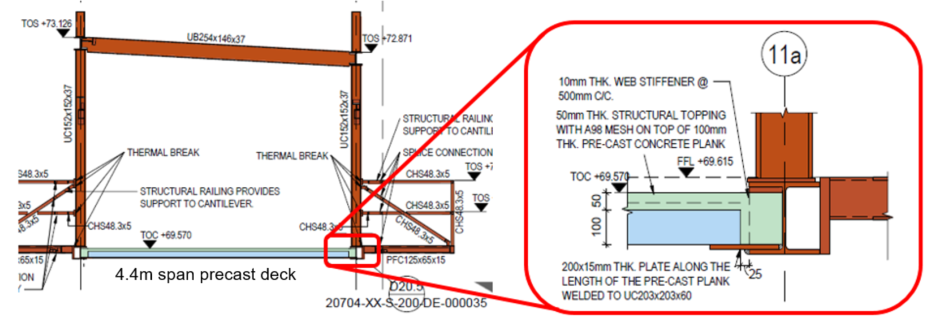
These beams have to carry not only passengers, but also electrical passenger vehicles (up to 5kN/m2). A 100mm concrete precast decking solution using Bison beams with a 50mm screed reinforced with mesh has been specified by the designer (see Figure 3 below – Bison beams specified in notes).
Here come the problems: According to the contractor, Bison are no longer able to provide the 100mm decking solution and this issue has gone back to the designer. A composite deck with steel profiling is not possible due to deflection limitations set out in the specification (limited to span/360). The designer claims that there are no suppliers who are willing to provide a solution and a redesign is required. However, having had a quick search of suppliers myself, there do seem to be some out there who can meet the spec – maybe the designers haven’t looked hard enough? I’ve not had chance yet to enquire with the designer about this.
From the client point of view there is a reluctance to change the design to accommodate a deeper decking. The first is that by increasing the thickness of the precast concrete decking slabs, the screed would be thinner; risking cracking issues if there are deflections. I would think that this may not be an issue as the precast decking would have pre-tensioned reinforcement? However, the spec (from Gatwick) states that crack widths are limited to 0.1mm and although this seems rather excessive, maybe this is a legitimate concern.
The second reason is that in changing the design thickness of 100mm, the designer would have a reason to add delays to the design of the bridge (which is already delayed and not yet finalised). As they are on a cost reimbursable contract (the reasons for this in itself are enough for a separate discussion!) any major design changes will incur a heavy cost. I think this may be why the designer hasn’t really investigated all 100mm decking options as there is no incentive for them to do so under this kind of contract. Instead I suspect they want to use this as a reason for delay to the design schedule by significantly changing the deck design.
As a side note there are also challenges around the temporary works and scaffolding required to enable the project. However, I think this deserves its own blog post so I’ll leave you on the edge of your seats for my next exciting instalment.
Constructionarium
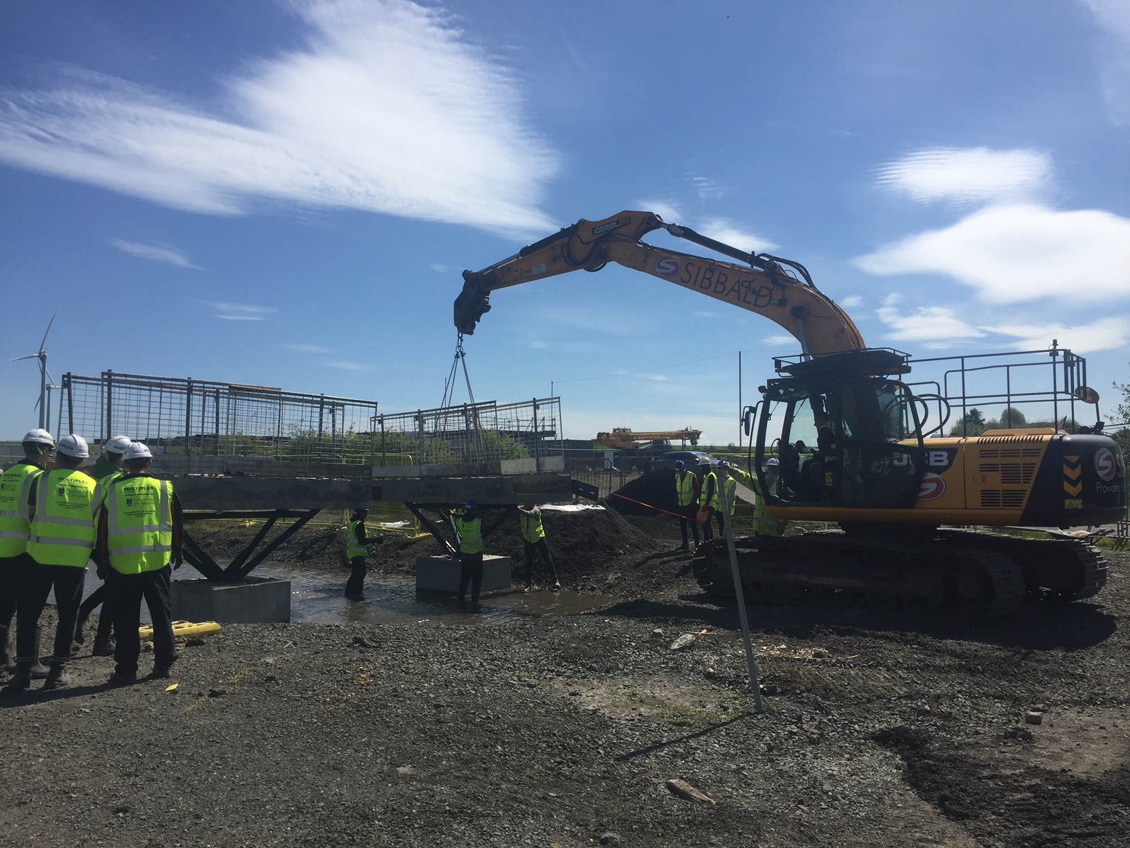
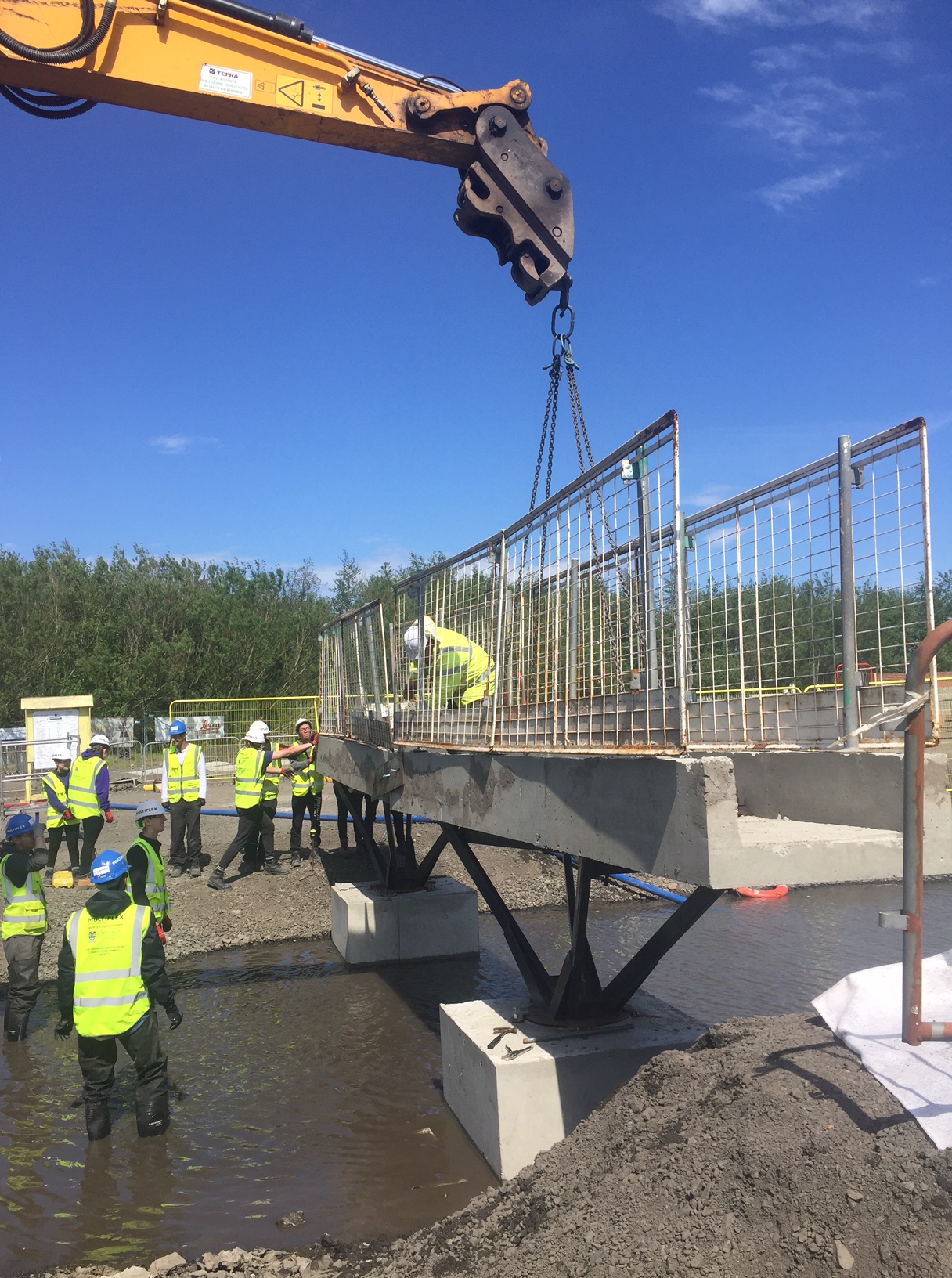
Summary. I recently attended Constructionarium in central Scotland on behalf of Multiplex. Here I acted as a client/mentor while Civil Engineering students from Glasgow University constructed scaled down versions of infrastructure and building projects.
Background. The scheme is ran across the UK with a large number of universities and companies sending their students/graduates on it to develop practical construction experience. Teams of approximately 12 are split into roles from project managers, setting out engineers and quantity surveyors and are given a set of drawings and specifications for their allocated project. Alongside their allocated role they act as operatives while skilled assistance is provided by the training supplier such as plant operators and appointed persons.
Detail. The event runs Mon – Fri and all the materials and equipment are provided by the supplier. The team are not however informed exactly what they need and so it is amusing to watch them level ground with shovels for 3 hours before realising they could have requested a light wheeled tractor. It is encouraged that the students are left to make mistakes as part of the learning process and simple problems like failing formwork provided platforms for discussion on structural analysis. They are required to produce RAMs, obtain permits to work, conduct toolbox talks, inductions etc all in line with realistic outputs of a competent contractor.
")
")
Military relevance. Constructionarium Scotland is a non profit organisation and the director was keen to promote its potential value as a training method for the military. I have summarised some pros and cons below:
+ All inclusive cost for 1 week training is £150-200 per person (including lunch, eqpt + materials – minimum numbers are 20 people). For context, 1 week pre deployment training (PDT) in Chatham for a B&SF costs approx. £750 per person.
+ Training can be tailored to suit learning objectives. For example more experienced tradesman can be pushed in areas of planning, health and safety, resourcing etc.
+ One stop shop would make planning of the training straight forward. Site is clear, free of contamination and includes welfare facilities and security.
– Obtaining financial approval for training from Brigade may be difficult, even if justified as PDT.
– Greater value was achieved through higher training numbers, for example we had 54 students and they could learn from different projects. Engineer regiments may struggle to get this amount of manpower available for additional training.
– Experiential learning training benefits are harder to articulate than straightforward courses. For example a week’s PDT at Chatham for a B&C may include a scaffold ticket whereas Constructionarium did not include this type of validation.
– PDT may be better utilised practising construction directly relevant to the projects to be undertaken on deployment.
")
")
Sustainable Generator Fuel Trials
In an effort to minimise CO2 emissions and disturbance to the local community we are trialling the use of two hydrogenated vegetable oil generators. These are required to power the tower cranes over a two week period while we move a sub-station connection and transfer from low to high voltage supply.
The ‘Green D+’ fuel is made exclusively from waste products comprising a mix of vegetable oils and animal/fish fats. Unlike regular diesel hydrogen is used as a catalyst in the process instead of methanol. This is therefore a sustainable fuel source which saves one tonne of carbon for every 350 litres of fuel burned. We are expecting to save 68.5 tonnes of carbon from this trial – equivalent to roughly 14 personal flights from London to Sydney.
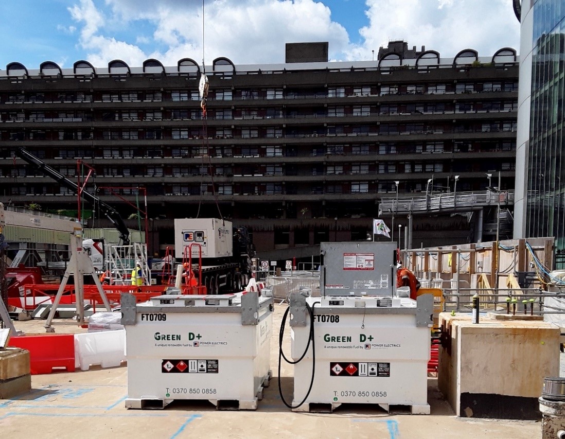
Beyond its carbon benefit, it also achieves a 29% reduction in Nitrogen Oxide (NOx) emissions and a 77% reduction in airborne particulates compared to red diesel, and therefore reduces air pollution to the local community. The high cetane value of the fuel (70+) also reduces combustion noise, sometimes referred to as ‘knocking’ noise, which is so often associated with the running of a generator on site.
Downsides are a marginal increase in cost of the fuel and the whole site smells faintly like a chip shop. But we’re saving the planet.
Environmental benefits:
- Reduction in carbon emissions
- Use of waste materials
- Reduction in noise and air pollution
Business benefits:
- Stakeholder engagement (community and City of London)
- Small trial of potentially beneficial technology
When it all goes to SLUMP
G’Day from Melbourne, Australia!


The work is just starting to pick up on my site at the West Gate Tunnel Project (Maribyrnong River Crossing Site) as we prepare to start installing precast concrete piles on land based bridge piers and steel tubular driven piles in the river (due to start over the next 2-3 weeks).
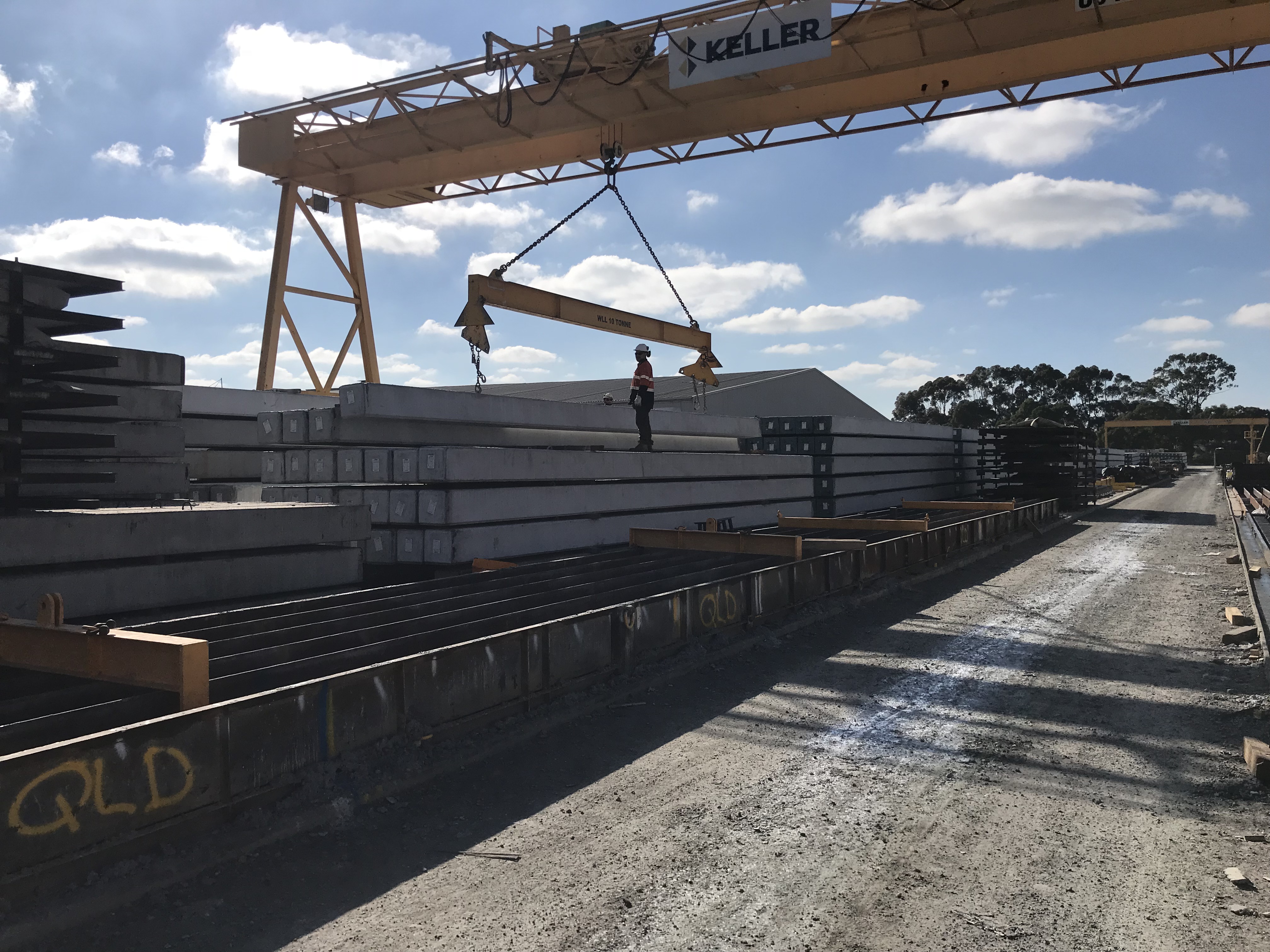
The precast piles are being utilised for foundations across almost the entirety of the WGTP, culminating in thousands of individual piles in total. Although the project has its own precast yard, the procurement of precast piles has been subcontracted to piling specialists ‘Keller’s’, who are manufacturing the piles, delivering them to site and driving them into position.
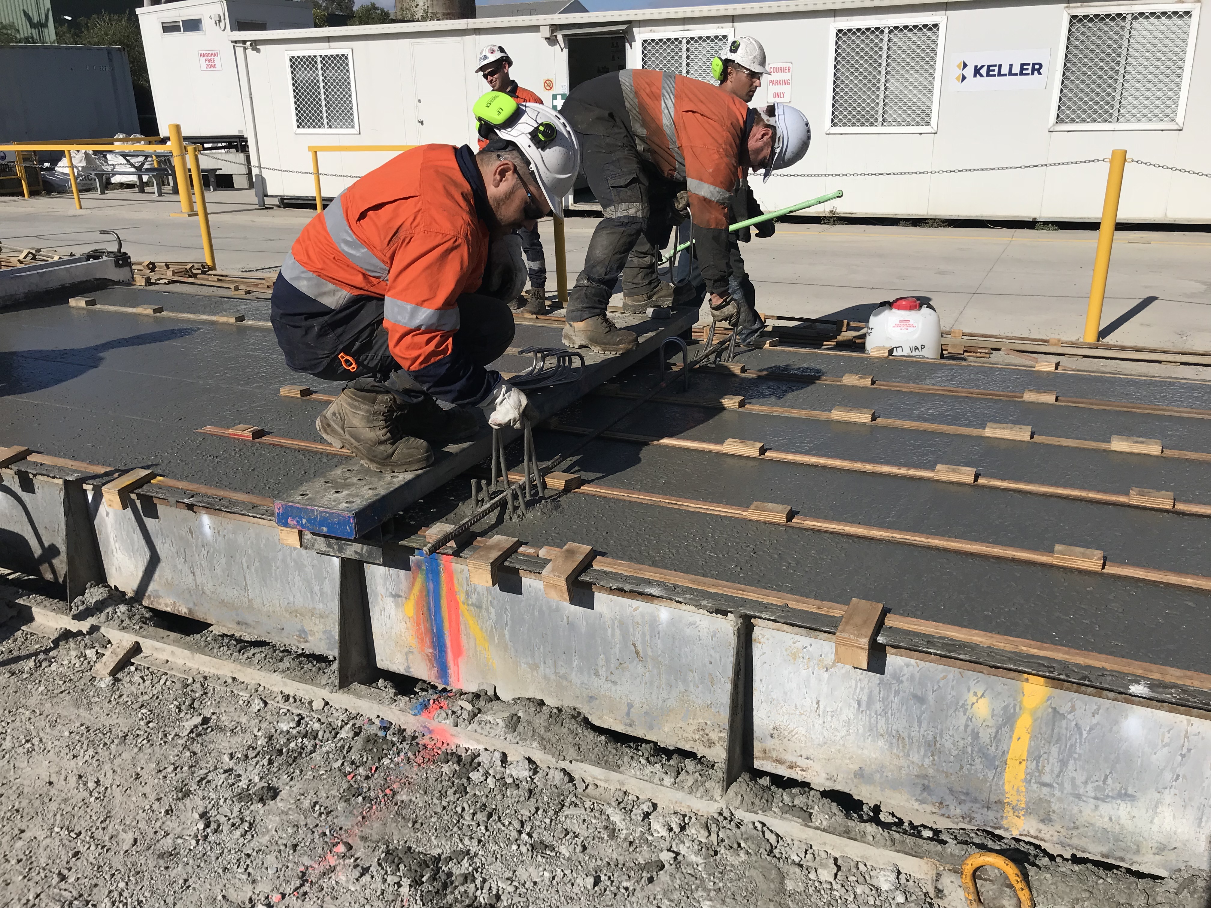
Today saw the first four piles for my site cast. As part of the quality assurance, the IREA (third party auditor) are required, under the Inspection Test Plan to conduct inspections of the reinforcement and concrete mixture, under a Hold Point, prior to pour. I decided to go along for the day and capture this procedure and provide assurance that checks were being carried out in accordance with the ITP.
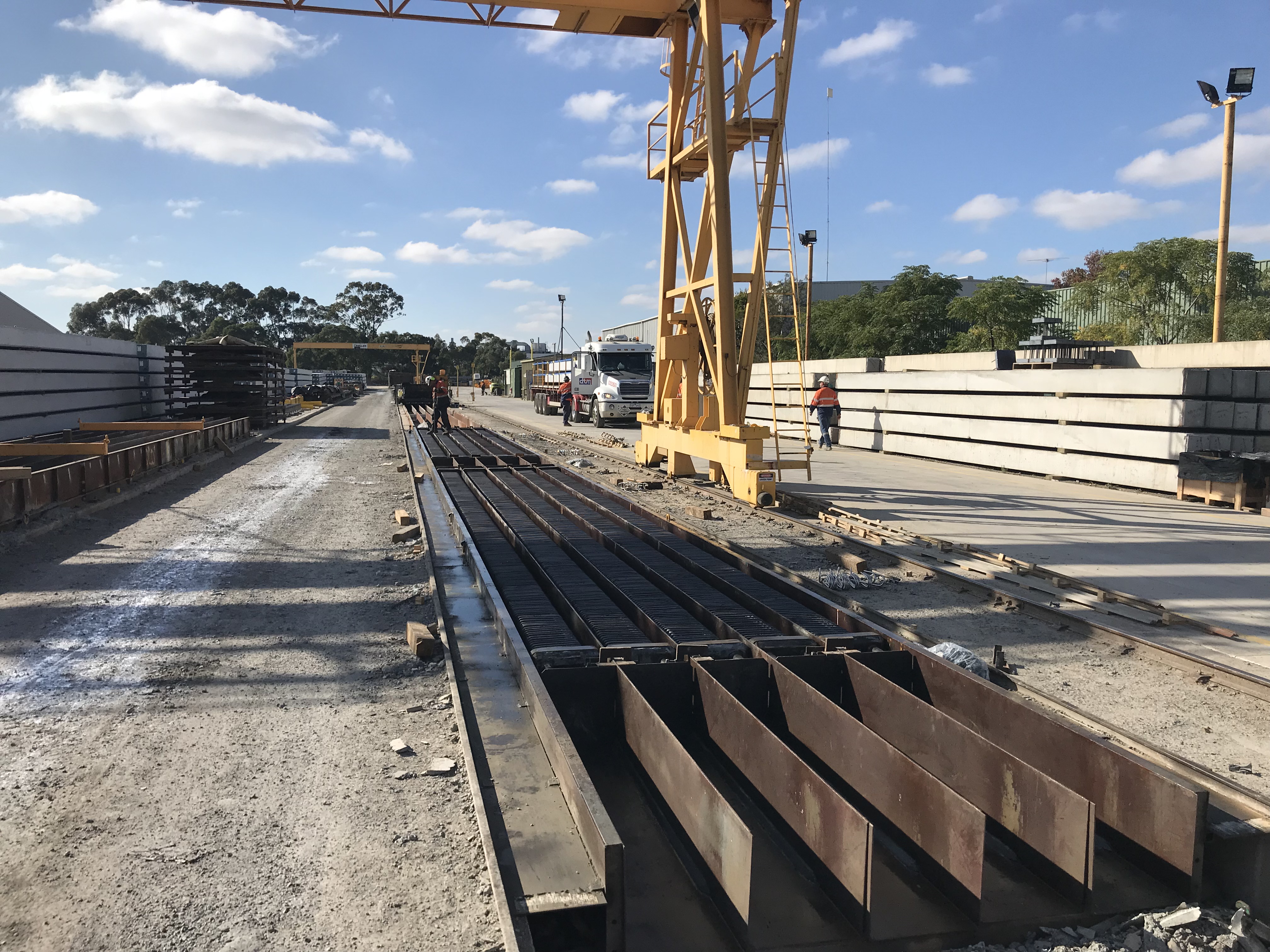
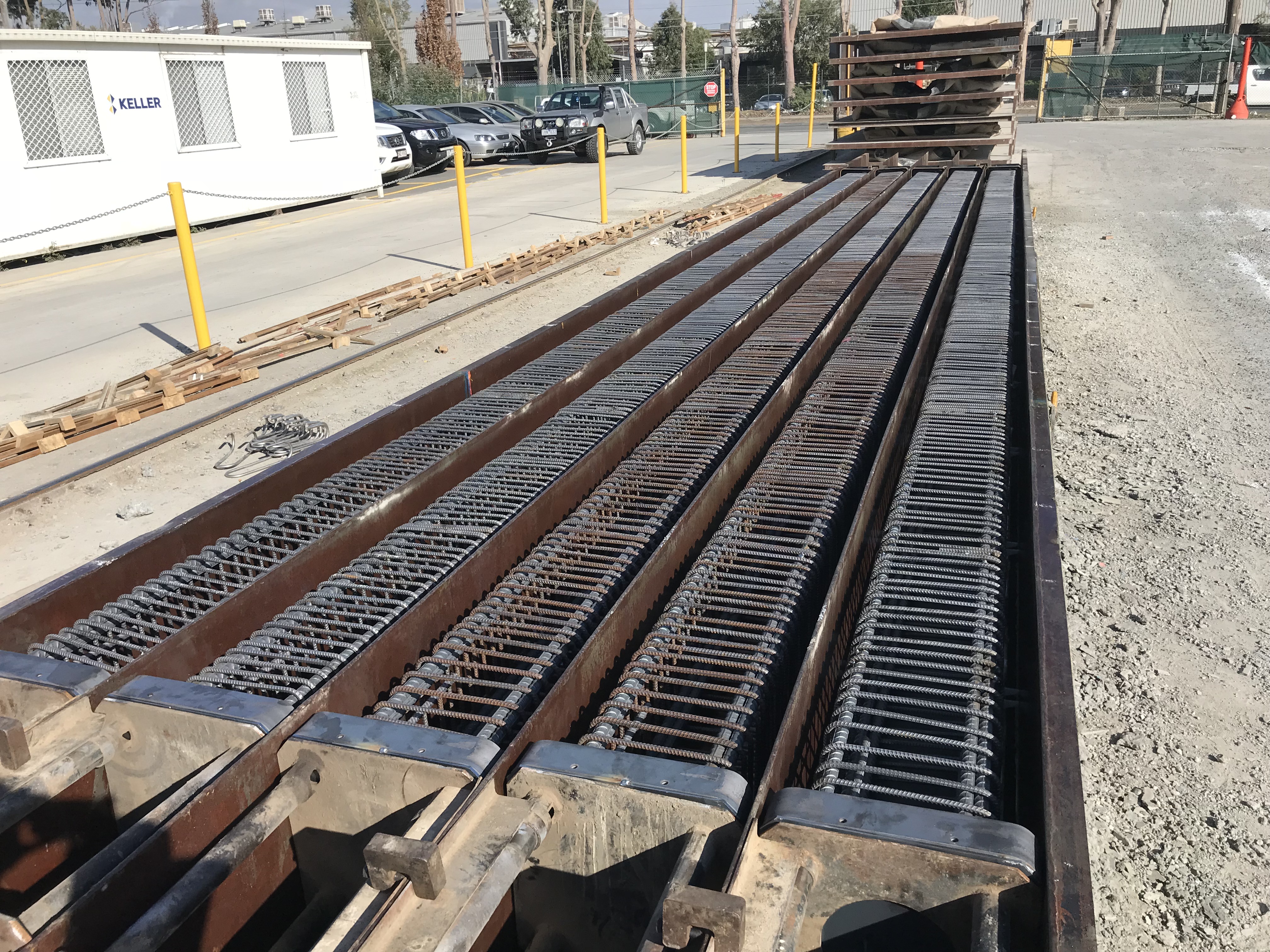
The Casting yard is a rather simple and effective set up, involving runs of four moulds for approximately 100-150m or so. The reinforcement cages are lifted into moulds, onto spacers (to ensure cover requirements are met) and then cast continuously throughout the afternoon from concrete agitators. As mentioned previously, Keller’s are manufacturing thousands of these piles, in various lengths and with several reinforcement details. Meaning a slick manufacturing operation is now in process. A typical day runs as:
- 0600 – strike previous days cast from mould and stack onto dunnage;
- Clean moulds and prepare lengths;
- Install reinforcement cages;
- Conduct QA checks;
- Cast moulds (checking concrete mixture through slump and cubes samples)
The piles are stored in the yard for 7 days, at which point they are transported to site, where they must continue to cure for a further 7 days prior to driving; this allows adequate time for compressive strength of the concrete to be achieved (60MPa in this case).
Today, I got the chance to witness the importance of slump testing. The slump test for the concrete mixture had a range of 160mm-240mm slump. The second mixer to arrive on site was tested on arrival (as are they all) by a subcontracted specialist (Construction Sciences), and a slump of 110mm was measured. This resulted in the concrete batch initially being refused; not great considering half the pile lengths were cast and continuous pouring was required. As the slump water/cement ratio was too low, a simple solution was possible, add more water!
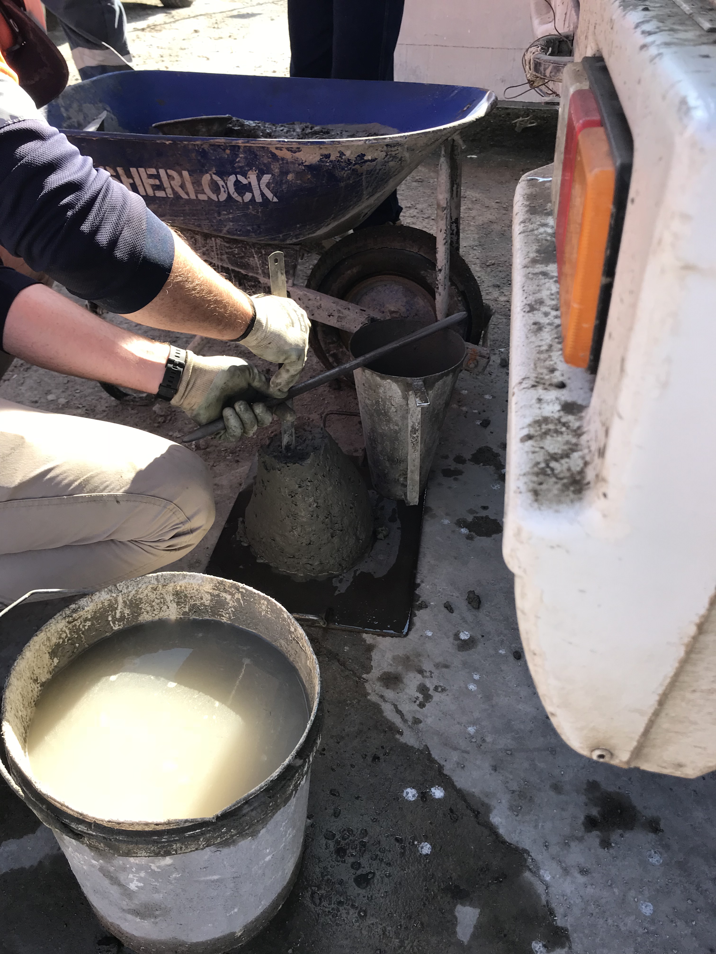
Clearly the question to be asked was, ‘how much water?’. Of interest was to see the difference in approach between the engineers and concreters on site. The engineers, as you’d expect, started conducting calculations to estimate the volume of water needed to reach the required slump. The concreters decided to go with the more traditional ‘this is what we did before, that looks right’ approach, as if from nowhere, to which they tried to argue was correct; clearly the calculated route was taken forward …. and proved correct.
From this experience, I learnt the importance of simple and quick testing on site and the need to take a calculated and measured approach to problem solving as it appears the ‘guys’ on site will just crack out the ‘this is what we did before’ line; something that you seem to hear a lot.
I’ll be sure to put some stuff up once the piling starts, especially the marine piles and the dynamic testing involved.
