When it all goes to SLUMP
G’Day from Melbourne, Australia!


The work is just starting to pick up on my site at the West Gate Tunnel Project (Maribyrnong River Crossing Site) as we prepare to start installing precast concrete piles on land based bridge piers and steel tubular driven piles in the river (due to start over the next 2-3 weeks).
The precast piles are being utilised for foundations across almost the entirety of the WGTP, culminating in thousands of individual piles in total. Although the project has its own precast yard, the procurement of precast piles has been subcontracted to piling specialists ‘Keller’s’, who are manufacturing the piles, delivering them to site and driving them into position.
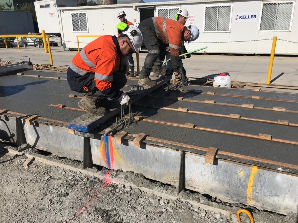
Today saw the first four piles for my site cast. As part of the quality assurance, the IREA (third party auditor) are required, under the Inspection Test Plan to conduct inspections of the reinforcement and concrete mixture, under a Hold Point, prior to pour. I decided to go along for the day and capture this procedure and provide assurance that checks were being carried out in accordance with the ITP.
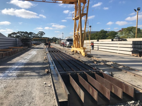
The Casting yard is a rather simple and effective set up, involving runs of four moulds for approximately 100-150m or so. The reinforcement cages are lifted into moulds, onto spacers (to ensure cover requirements are met) and then cast continuously throughout the afternoon from concrete agitators. As mentioned previously, Keller’s are manufacturing thousands of these piles, in various lengths and with several reinforcement details. Meaning a slick manufacturing operation is now in process. A typical day runs as:
- 0600 – strike previous days cast from mould and stack onto dunnage;

- Clean moulds and prepare lengths;
- Install reinforcement cages;

- Conduct QA checks;
- Cast moulds (checking concrete mixture through slump and cubes samples)
The piles are stored in the yard for 7 days, at which point they are transported to site, where they must continue to cure for a further 7 days prior to driving; this allows adequate time for compressive strength of the concrete to be achieved (60MPa in this case).
Today, I got the chance to witness the importance of slump testing. The slump test for the concrete mixture had a range of 160mm-240mm slump. The second mixer to arrive on site was tested on arrival (as are they all) by a subcontracted specialist (Construction Sciences), and a slump of 110mm was measured. This resulted in the concrete batch initially being refused; not great considering half the pile lengths were cast and continuous pouring was required. As the slump water/cement ratio was too low, a simple solution was possible, add more water!

Clearly the question to be asked was, ‘how much water?’. Of interest was to see the difference in approach between the engineers and concreters on site. The engineers, as you’d expect, started conducting calculations to estimate the volume of water needed to reach the required slump. The concreters decided to go with the more traditional ‘this is what we did before, that looks right’ approach, as if from nowhere, to which they tried to argue was correct; clearly the calculated route was taken forward …. and proved correct.
From this experience, I learnt the importance of simple and quick testing on site and the need to take a calculated and measured approach to problem solving as it appears the ‘guys’ on site will just crack out the ‘this is what we did before’ line; something that you seem to hear a lot.
I’ll be sure to put some stuff up once the piling starts, especially the marine piles and the dynamic testing involved.

Dan nice post!
A few thoughts/questions from me as I’m interested to compare with what is happening on my site.
My understanding from your post is that the design slump was 160 – 240mm. Is that correct or was that the range of previous pour slump tests? The concrete I’ve been pouring into a foundation over here is N40 MPa with an 80mm slump. Under the RMS general concrete specification, we conduct a slump test and take 3 cylinders every 50m^3. The tolerance for the slump test is +/- 15mm so my allowable range was 65 – 95mm. What tolerance is Keller working to for the slump tests? Also is a high slump required for workability during placing and to ensure the concrete moves around the reinforcement cage into the bottom of the form?
I was interested to read that you are taking cubes for strength testing. I was under the impression from the concrete testers I’ve had on site that the Australian Standard is based on cylinder tests. Was the decision to use cubes driven by the testing machine or another reason? Also what is the crushing regime for the samples? My project is producing pre-cast planks for a temporary boat ramp. Three sets of cylinders are taken each pour to provide 1-day, 7-day and 28-day strength results. The 1-day results are used to determine when to strip the forms. Are Keller crushing at 1-day, 7-days and 14-days instead?
I liked the simple solution to the problem = add water… but the dilemma of how much? I take it the delivery docket didn’t state the amount of ‘free water’ you could add. None of my dockets have and all the cement truck drivers were initially turning up ‘dry’ with a slump of about 55-65mm as they don’t want to get turned away. After 3 weeks of visually inspecting every delivery alongside a concrete tester, I’m surprised at how easy it is to predict the slump and determine if additional water is required.
Good to see you’re enjoying the sun down in Melbourne too.
Hi Mark. thanks for the comment.
My bad! I meant cylinders not cubes, good pick up! The design slump for the mixture is 200mm. As you’ll be aware, the slump test provides a consistency check of the concrete i.a.w. AS 1012.3.1. In Victoria state, we work to ‘VicRoads’ standards, which will be different to what you are working too; though I’m sure they are similar. Structural concrete is covered under VicRoads 610. As per Table 610.162 (see below), for a design slump of over 150mm a tolerance of +/- 40mm is stated; hence the 160-240mm I mentioned in the text.
Specified Slump (mm) Tolerance (mm)
80 ≤110 ±20
>110 ≤150 ±30
>150 ±40
As per VicRoads 610.16, compressive strength tests for in-situ concrete require 1 sample to be tested at 7 days and two (minimum) at 28 days. The volume of one pile (dimensions: 0.4m x 0.4m x 14m long) is approx. 2.24m³. With 5 piles being poured simultaneously, the requirement for a continuous pour is approx. 11m³, meaning we are taking 2 of these samples (2 lots of 1x7day and 2x28day). This is in line with table 610.161 (see below). Keller’s are not crushing at 1 day, just those mentioned above. My understanding is that yes, due to the difficulty of ensuring concrete is adequately spread underneath the cage within the mould, a high workability is required.
Volume Cast in One Continuous Operation (m³) Min. no. of samples
0 to 10 1
10 to 25 2
25 to 50 3
50 to 100 4
For each additional 50 m³ one additional sample shall be taken.
With regards to the docket, the max w/c ratio was recorded and the slump max water was recorded. Same with you 9and apparently Glynn – see comment below), it seems as if they wanted to under rather than site instead of risk being turned away. Speaking with guys in the UK, adding water on site is not permitted with some contractors, but that is not the case here.
Thanks for taking the time to reply Dan. Interesting to see the difference between the VIC and NSW test requirements.
For the permanent bridge works there are set guidelines for the time between batching a mix at the plant and discharging the load into the pour (the exact time depends on the mix and additives). The addition of free water is much more tightly controlled as you would expect.
Hmmm
So I guess the pile concrete and reinforcement is to enable pitching rather than resistance of diving stresses?
Shouldn’t be too difficult to prove the concrete strength and steel requirement ; on which point there would appear to be heavy shear resistance – or is this, more likely to be crack control steel?
Which brings me to the slum testing; without plasticiser I would guess it might be tricky to get 60MPa with a 240mm slump.
I am pretty sure that at a slump over100mm a concrete is considered fairly high slump. At over 200mm slump I thought that it was no longer a slump test but a flow table test?
CS BS EN 1230-5
Hi John,
Apologies for the late reply, I don’t seem tog et notifications!
Eight N24 bars are being used as the longitudinal reinforcement. These have been designed to resist the bending stresses induced from pitching and, from my understanding, bending stresses induced from potential bending during driving (i.e. to stop piles bending should they hit obstructions or rock and try to bend/twist (shear links to resist this torsion)).
The links along the pile are N10 helix bars with a pitch of 50mm towards the ends of the pile, where driving stresses are highest, and reduces towards the center of the pile (100mm) where stresses reduce; at least that was the design. It appears that the subcontractor has nominated to carry the shear links at the same pitch along the length. I would assume this is to save time, though considering the volume of piles being produced, this would seem silly in terms of cost with regards to steel. My understanding is that this reinforcement also resists the high torsional stresses induced during driving. Judging by the max pitching of 100mm, I would suggest this isn’t for crack control, but indeed the expected shear/torsional forces.
With regards to the slump test, the slump design is 200mm. As per table 610.162 (reference Mark’s comment reply above), the 240mm was meant as the upper tolerance. The 60MPa at a 200mm slump is achieved through use of superplasticizer and is in accordance with Vicroads 60113(c) for highly workable concrete (“highly workable concrete shall be superplasticised with a nominated slump between 160mm and 220mm”). Because Superplasticizer is being used, consistency is determined by a slump test (reference VicRoads 610.16(c)), therefore not a flow table test.
Interesting. BS EN 206:2013 Consistency category S4 for slump. Nothing is measured to intervals other than the nearest 10mm. Aus standards might have diverged but they were based on this, which is pretty universal. Was it slump and w/c ratio that were incorrect? Presumably there was delivery ticket with the w/c ratio and cement content recorded on it so that the permitted addition could be calculated if not already specified?
As can be seen from table 610.161 (reference Mark’s comment reply) slump is designed to the nearest 10mm, but tolerance allows for +/- 15mm for a 60-80mm design slump. The Water/Cement Ratio, as per the mix design, is 0.29. (more details on admixtures under John’s comment). The slump did fail, but was too dry. The first procedure is to take a second slump, and if that fails, the batch is rejected. In this instance, Keller (Subcontractor) selected to increase the water content in consultation with the testers. My understanding is that some contractors in the UK don’t allow this practice on site and would just reject the batch, but that is not the case here.
The docket was used to calculate the additional water required, but, as Glynn’s comment below, the ‘concreters’ on site just seemed to pluck a number out the air. Luckily it was not their decision. Suffice to say that the calculated water increase worked.
Hi Dan, we had a very similar issue on my phase 2 site with Keller and concrete specifications. My guess would be that their finger in the air method suggested adding 20L of water? I assume you will be using VICROADS specs for concrete testing? One to read up on is the timeline for the addition of water after the batching time. I can’t remember exactly, I would need to re-read the spec, but there is a very small window of time (depending on distance from the batching plant) where the addition of water on site is allowed to conform with the specification. In the end, we printed this timeline on the reverse of our ITP to ensure that the engineers had a method of ensuring conformance. It proved useful and several batches were turned away due to non-conformance.
Also, there is an interesting contractual issue in this problem and from my experience with Keller, I would be careful who is signing the ITP to say that the concrete on site conforms to the specification. We had the same approach as you, an engineer from the main contractor (CYP) would oversea the concrete pours and sign a CYP ITP to say that they had witnessed the testing and conformance. However, as part of the piling contract with Keller, they were responsible for ensuring the concrete conformed to VICROADS sepcfications and it was their call whether to accept a batch of concrete or not. Too often, Keller would try to pass this decision (and risk) to the CYP engineer on site to make the call whether to accept a batch or work out the additional water requirements. If the concrete ends up failing a later strength test (14/28 day test) and the pile has already be put in the ground, supported by a signature on the ITP from the main contractor, then there isn’t much room to move in any later disputes. Your contract may be different than ours, but worth identifying where the risk lies with the signatures you are being asked to add to an ITP, especially if a copy of the ITP ends up going to the subcontractor.
Thanks for the feedback on your experience.
As you mention, this Hold Point was under the authority/signature of Keller, so risk was not held with us. We were careful to not make any decisions to them, and left this as their issue to resolve. As the Hold Point sits with them, they have signed this. That’s an interesting idea with regards to the timeline to ensure engineers can oversee decisions, but ultimately, the decision sits with Keller. I’ll dig into VicRoads to ascertain delivery time/distance for adding water. All I have seen in VR610 is the requirements of the mechanism supplying the water.