Archive
Engineering Judgement vs Specifications
Over the last 2 weeks we have started installing precast concrete piles on my site using, from what I can tell from research and talking with previous PET(C) students working in Melbourne, a very experienced piling contractor (Keller). The first 7 days of piling have seen several pile caps complete, with over 50 piles installed; a total of 548 are being installed over the next 12 months, excluding CFA and Steel Driven piles.
Those who read my last blog will have seen the QA and testing process implemented on site to ensure compliance of piles against the design specification. As the Project Engineer tasked with overseeing these works, I have been involved daily with inspections of precast concrete pile deliveries and PDA testing, whilst managing the site engineers.
Since my last blog, a concrete patch repair procedure has been accepted by the IREA (third party auditor) and the Nominated Authority (in house auditor), meaning blow holes can now be repaired on site. It should be noted, however, that cracks cannot be repaired using this at this stage.
As part of the Inspection Testing Plan, the Nominated Authority own the Hold Point of testing of the piles to ensure geotechnical design capacity is reached. This week, we have had a few issues arise. One is that some piles tested are not achieving pile capacity on either end of drive or on restrike (see my previous post for more info). This issue is being resolved with the subcontractor and the designers to see how this can be dealt with. My SPE seems to think that we can still get away with the results we have by proving the end bearing resistance with quick calcs … I’m not so sure how this proves geotechnical design capacity? To me, the summation of shaft and end bearing resistance has failed to mobilise enough capacity, even after 3 days of ‘setting up’ prior to restriking. I would assume additional piles will be required, unless there was enough design contingency planned?
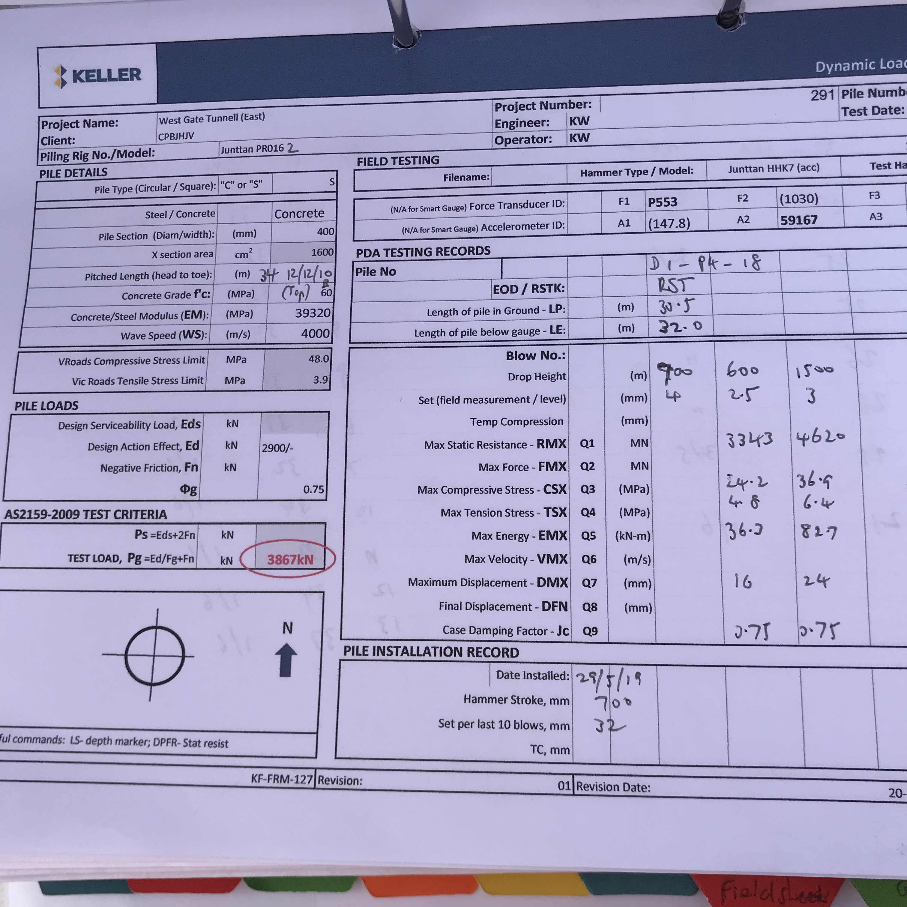
It appears that no piles are reaching geotechnical design capacity at end of drive. As per my previous post, the first pile in a group is driven under PDA monitoring to monitor driving stresses and set the driving criteria for the remainder of the group. I spoke with the testing engineer about this, who has over 20 years’ experience of PDA testing and just so happened to work for PDA in America previously (so I’m taking his advice as rather expert). He does not expect any pile to achieve end of drive resistance due to the high design capacity required (2900kN is the ultimate design load for most piles. This is given a reduction factor of 0.75, meaning 3867kN is required) given the short 12m/14m length of piles but is confident that, where a set of 35mm (average movement of the pile per 10 blows) is achieved, the capacity will be achieved given time to set up; i.e. capacity will be achieved on restrike (clearly not the case for some piles above).
What has surprised me is the huge variability in the basalt rock layer the piles are being driven to. It would appear that all our lessons on ground being a risk couldn’t be truer. The rock levels from the ground model (created from interpolation of boreholes) shows a nice straight line to design the pile toes to. As can be seen from the photo below, this is not the case. In some pile caps, variability increases by over 4m and more. This creates a cost issue, as, under VicRoads Specification 605, restrike tests are required to be carried out where toe levels of piles in a group vary more the + or – 2m. Each restrike test is a cost to us.
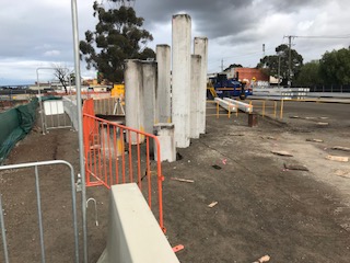
Front two piles can be seen to refuse much deeper than remaining piles due to variability in the basalt rock layer
The main issue we’ve had has been the releasing of a Hold Point under the Nominated Authority. If we are to go by the letter of the law, the VicRoads 605 specification and pile installation ITP (which takes the hold point straight from the spec) state that the first pile driven, which is under PDA monitoring, must have a restrike test if geotechnical design capacity is not reached on end of drive. For the pile and pile group in question, the first pile did not achieve the capacity at end of drive and is one of 10 piles in the group. It just so happened that this pile achieved the lowest set (21mm) of the group, with the highest set being 32mm. Under the VicRoads spec, only 10% of piles require a restrike, meaning only one pile required testing. Keller’s testing engineer, rightly in my mind, chose to test the pile with the 32mm set. For those unaware, the pile with the highest set is theoretically the pile in the group with the lowest geotechnical capacity. This is simply because the pile has moved more than any other pile under the same hammer weight and energy, therefore experiencing less resistance from the soils.
However, although ultimate geotechnical capacity was achieved on the restrike of this pile, the Nominated Authority refused to release the hold point because the pile test was not the first pile driven and monitored in the group. This seems silly to me. I would have thought that by proving the pile with highest set in the group, pile capacity of all piles has been proved? The logic of the testing engineer seems sound to me and I would argue that the intent of the spec is to prove capacity of the group, which I believe has been done?
The Nominated Authority, as has been the case with other issues, seem to blindly follow what is written in the spec and not apply any engineering judgement or consider the intent. In which case, what would be the requirement for engineers on site?
Either way, I have now had to raise a NCR to the Client to argue the case that capacity has been proven and that this method should be adopted moving forward.
Tearing it up
Having spent over 3 months watching 5no 13tonne excavators peck and break at my structure level by level (my first blog) a change in tactic has excited me enough to share.
Effectively due to the phone masts fixed to the central core not being decommissioned in time the central core remained upright while the rest of the building was demolished down to ground floor. This left the quandary of how to demolish the remaining core after the masts were finally decommissioned 3 months late.
The same tactic could not be employed as there was no ramp in the core which the plant could drive down so a crane would need to have lifted them from floor to floor. Also an entire scaffold wrap would have needed to be constructed around the core to offer edge protection, dust suppression and access to the workers. All of this was not impossible but potentially long winded.
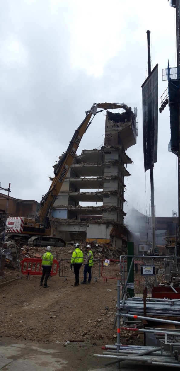
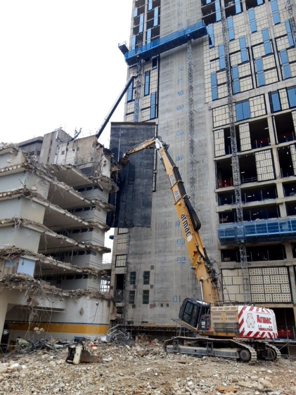
Instead the decision was made to pay for a 110tonne monster to come to site with an “extra long reach excavation arm” and demolish everything from the ground. This raised issues such as trying to suppress dust from the ground would have been impossible and flying debris at 40m flying around site. The solution- the long reach arm has a host attachment that sprays water from the breaker onto the slab as it goes. A large crane will hold up a rubber Matt to prevent debris hitting adjacent construction with an exclusion zone at ground level.
The site of this bad boy on site has produced a bit of a viewing gallery and some buzz on site so I thought I would post pictures. Any questions on the decision making or added risks feel free to ask.
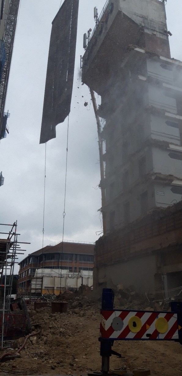
2 concrete sacks preventing the rubber matting twisting or glittering into adjacent construction

Childhood dream made reality – Lego meets construction
Whilst doing a bit of additional research for my CI paper presentation I came across a recent interesting news article. It seems that you can actually construct buildings out of giant plastic lego blocks! The pictures below show an urban training area being constructed at Camp Taji, Iraq by an Australian and New Zealand task group (news article here – 13 June 2019). The buildings were made using a system devised by a company called Everblock (official site here). The blocks claim to be durable and reusable which makes them potentially of interest to military construction. The blocks are also lightweight meaning faster construction, less operator fatigue and potentially less risk of lifting injuries.
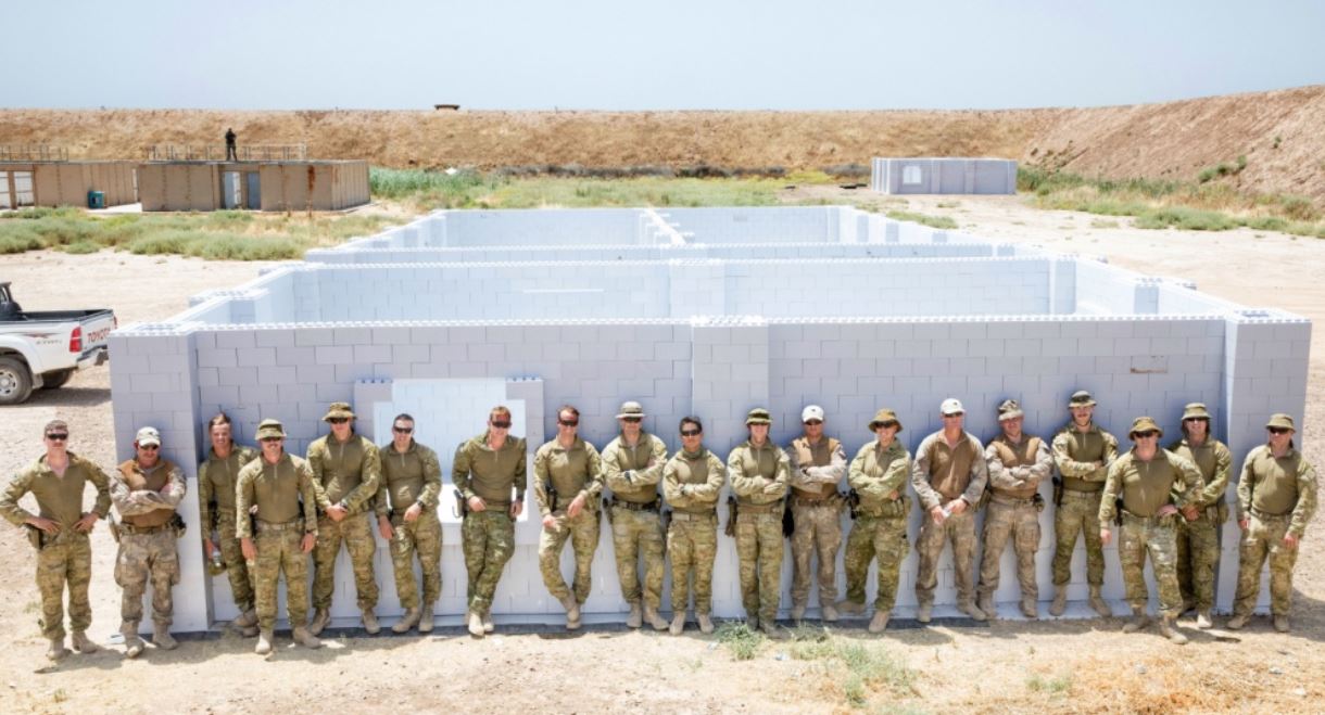
Having looked at the specifications it would seem that there are some fairly obvious limitations. These include poor thermal resistance and a limited resistance to fire (including toxic chemicals that may be released in the event of a fire). Whilst the system includes a dowel option to improve the building strength, I would be a little hesitant about building greater than one storey without more information. For these reasons I can see why they have only chosen to use this system for urban training at Taji, rather than as habitable structures. If anyone knows anyone working at Taji I would be very interested to get in touch to get further information on this project.

Limitations also mean that a roof structure would need a separate design. I’ve seen examples using timber or steel stringers with corrugated sheet roof cladding. Everblock also produce modular flooring though I would think that foundations might provide a challenge due to the minimal tolerances of building this way.

One option that might be interesting to explore is using recycled materials to make in-situ blocks similar to the Everblock system. Cement could be mixed with recycled plastic to potentially produce concrete blocks similar to this with improved thermal and fire resistance characteristics.
Finally Everblock have an online block builder here where you can relive part of your childhood and design your very own giant lego construction!
It always comes out in the wash…
Introduction
Gareth – it sounds like we could have done with the approach you describe in your blog post about 4 weeks ago… A little more attention to detail and closer supervision might have been of benefit!
The past few days have seen unsettled weather across eastern Australia. There has been snow in the mountains and even in the sunshine state (Queensland) to the north. The area I am in has survived largely unscathed however we have had high winds (gusting up to 130 kph stopping crane operations) and over 70mm of rainfall in one night (for perspective, site drainage is sized against a 37mm event).
Today was due to be the completion and opening of a new public temporary boat ramp which would allow us to close the existing boat ramp and start piling works on the temporary jetty. The jetty is required to transfer precast bridge elements from the shore onto barges in the river. At least that was the plan until 0705 this morning…
Background
Due to a number of delays, the senior site management has decided to conduct concurrent works to save costs and recover the programme. This has required a number of activities to be brought forward onto the critical path. To gain momentum on these activities some engineering ‘best guess’ has been applied in order to complete designs and gain environmental approvals. The temporary boat ramp is one example of this and there has been a big push to construct the temporary boat ramp as quickly as possible.
John Holland initially struggled to attract enough experienced site and project engineers so have backfilled with a number of engineers from their graduate programme. Sadly due to the lack of experienced engineers in the office and concurrent works, a lot is being asked of the junior engineers who are getting limited supervision from the experienced engineers.
To meet the required boat ramp construction timeline the decision was made to use the concreting contractor working at the precast yard. For two months they have been producing pre-cast boat ramp planks alongside the in-situ concrete foundation at the precast yard. The past two weeks have seen the workers move across to the boat ramp site to complete the in-situ concrete pours and install the pre-cast planks. The construction of the boat ramp has been nothing but challenging and from the sidelines, it has seemed like everything was ‘going off half-cocked’ resulting in poor quality finishes produced by the subcontractor (but that’s another issue). All the time this has rested on the shoulders of one of the graduate engineers.
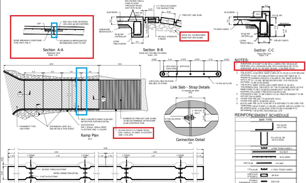
Temp Boat Ramp Drawing. Red boxes highlight the expansion joint detail and subgrade and rock armor notes. Blue boxes highlight the expansion joint.
So what happened?
This morning at the pre-start meeting (workers-management meeting) everyone was asked to check their areas for any issues. Shortly after the workers set off for the boat ramp the telephone calls started…
What follows are a series of photographs I took this afternoon at low-tide:

View from the existing bridge. The yellow and white floating items are silt and hydrocarbon booms which are part of the site environmental controls.
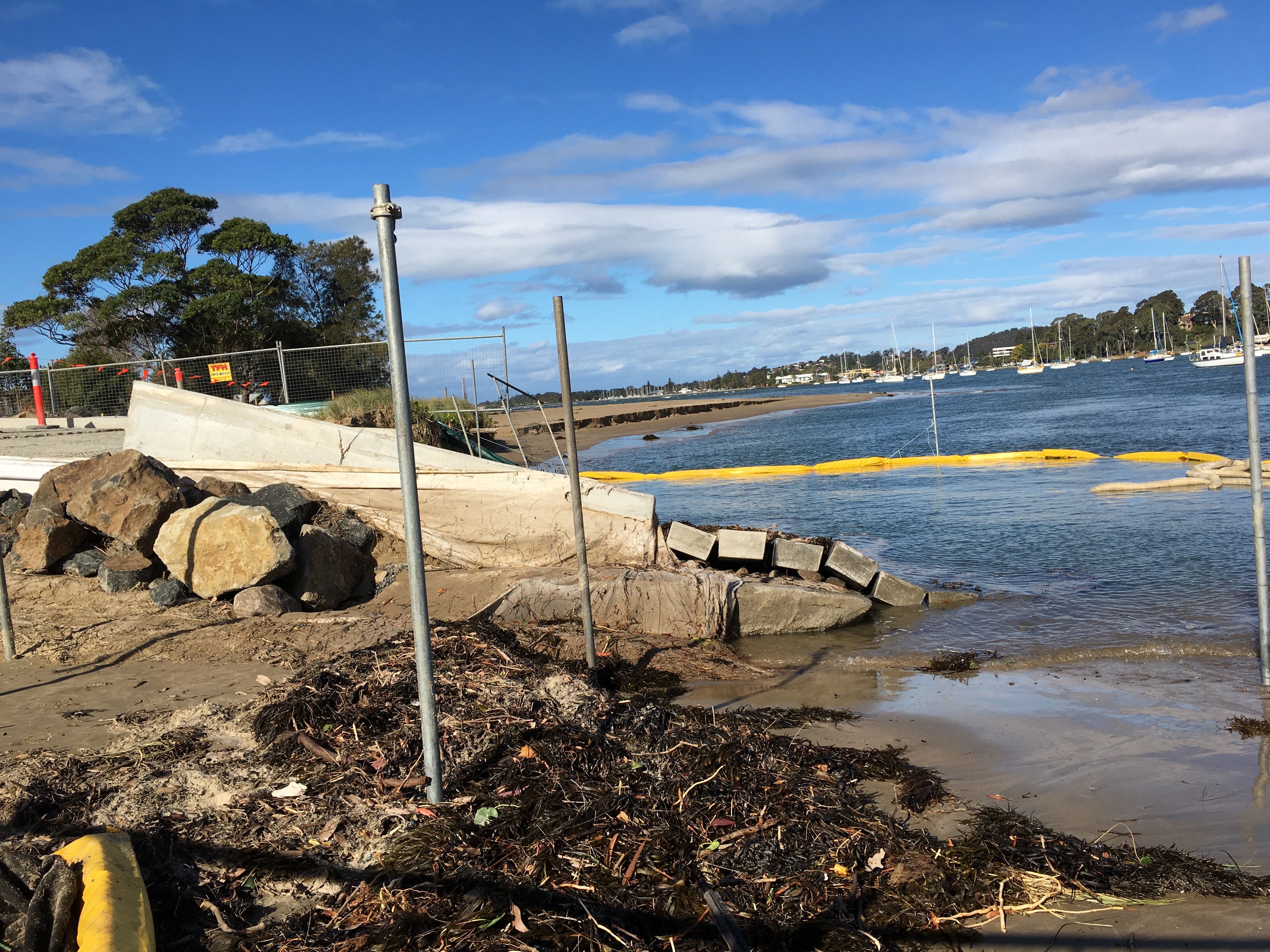
Side view from the bridge side. Note the rock armour on the left of the picture.

View standing on the ramp. Note the raised slab and seaweed position.
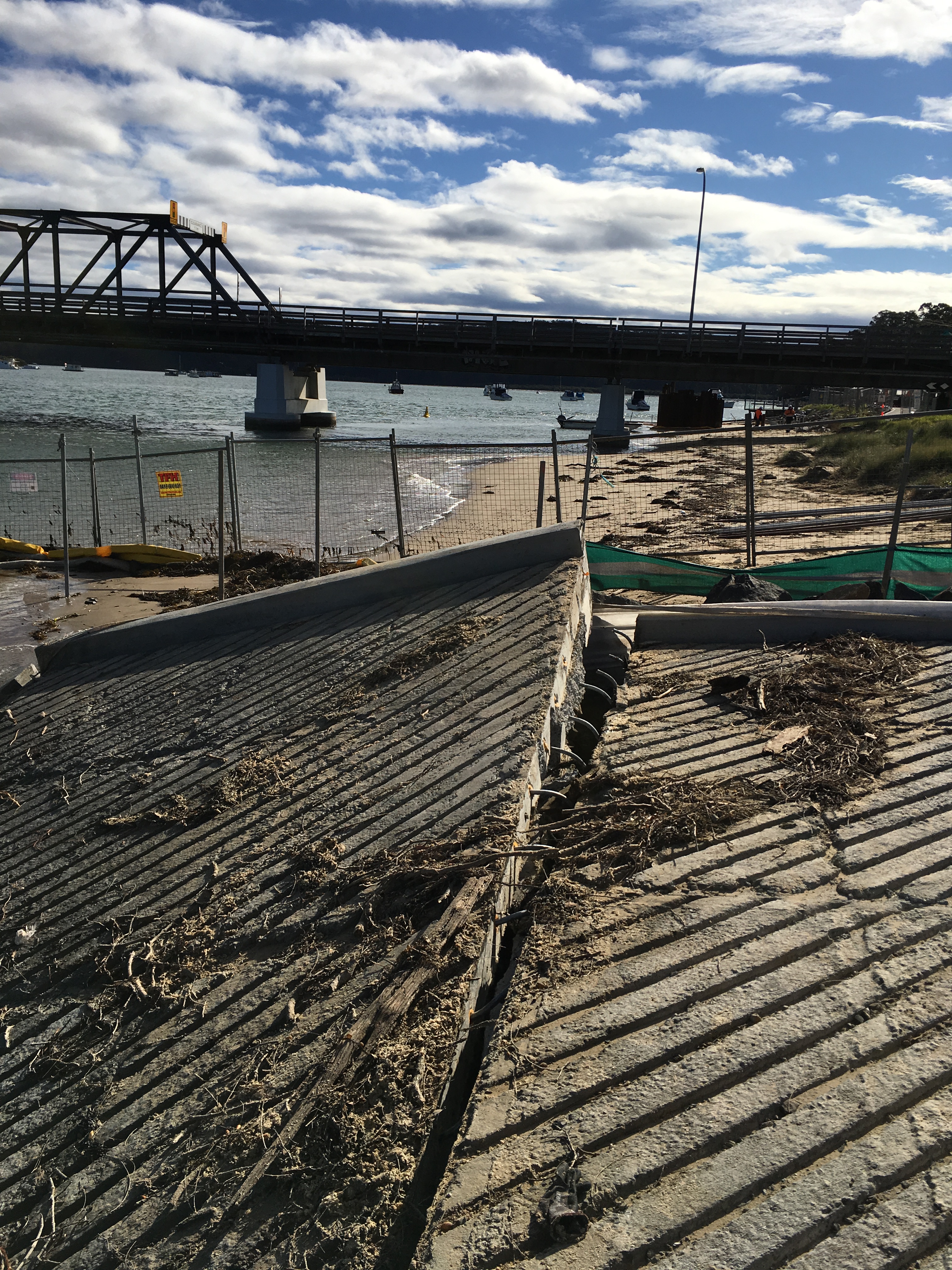
View back towards the bridge along the expansion joint. Note the curved dowels.
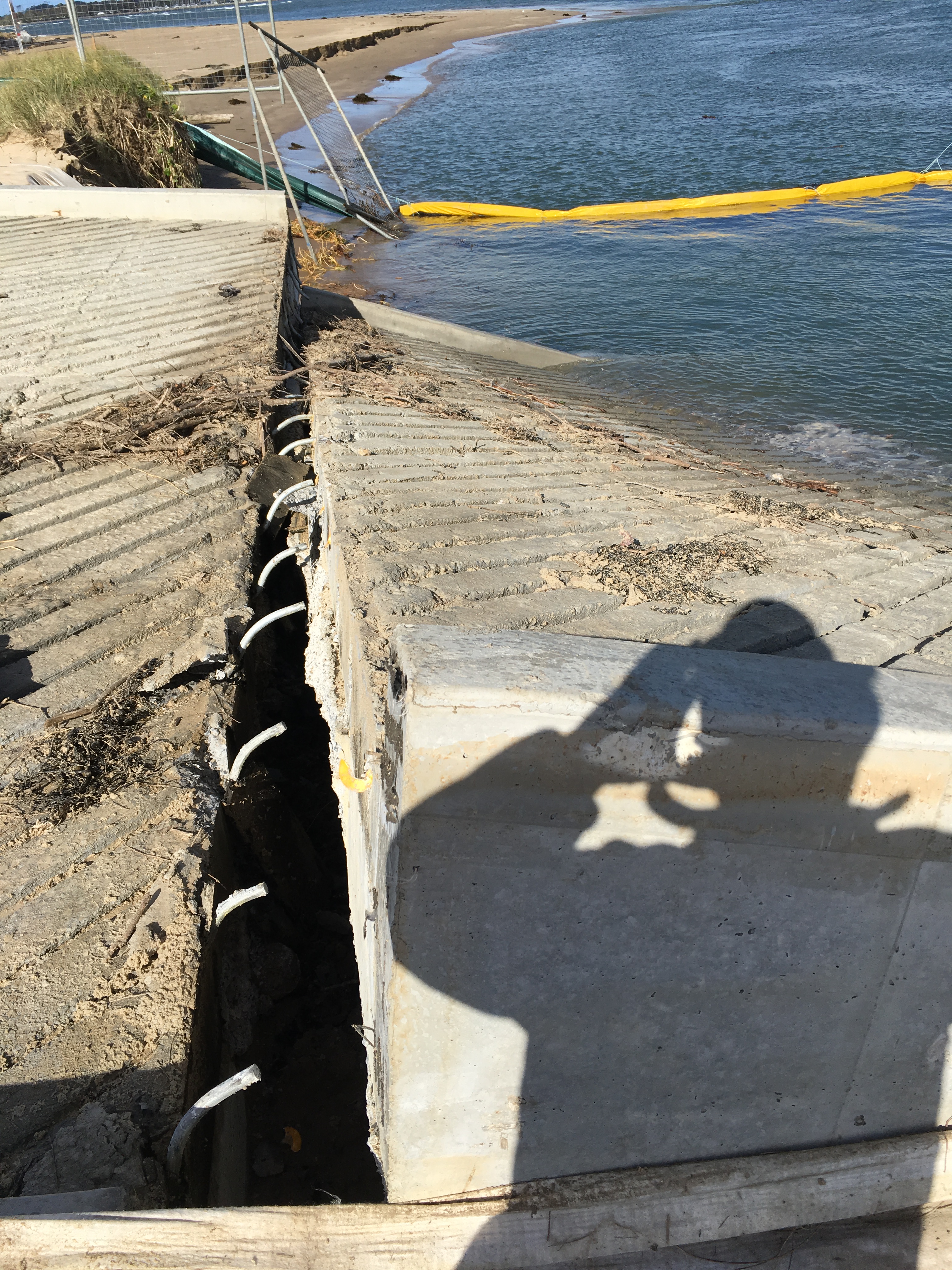
View along the expansion joint facing away from the bridge. Note the tilt and shift in the slab on the right of the picture.
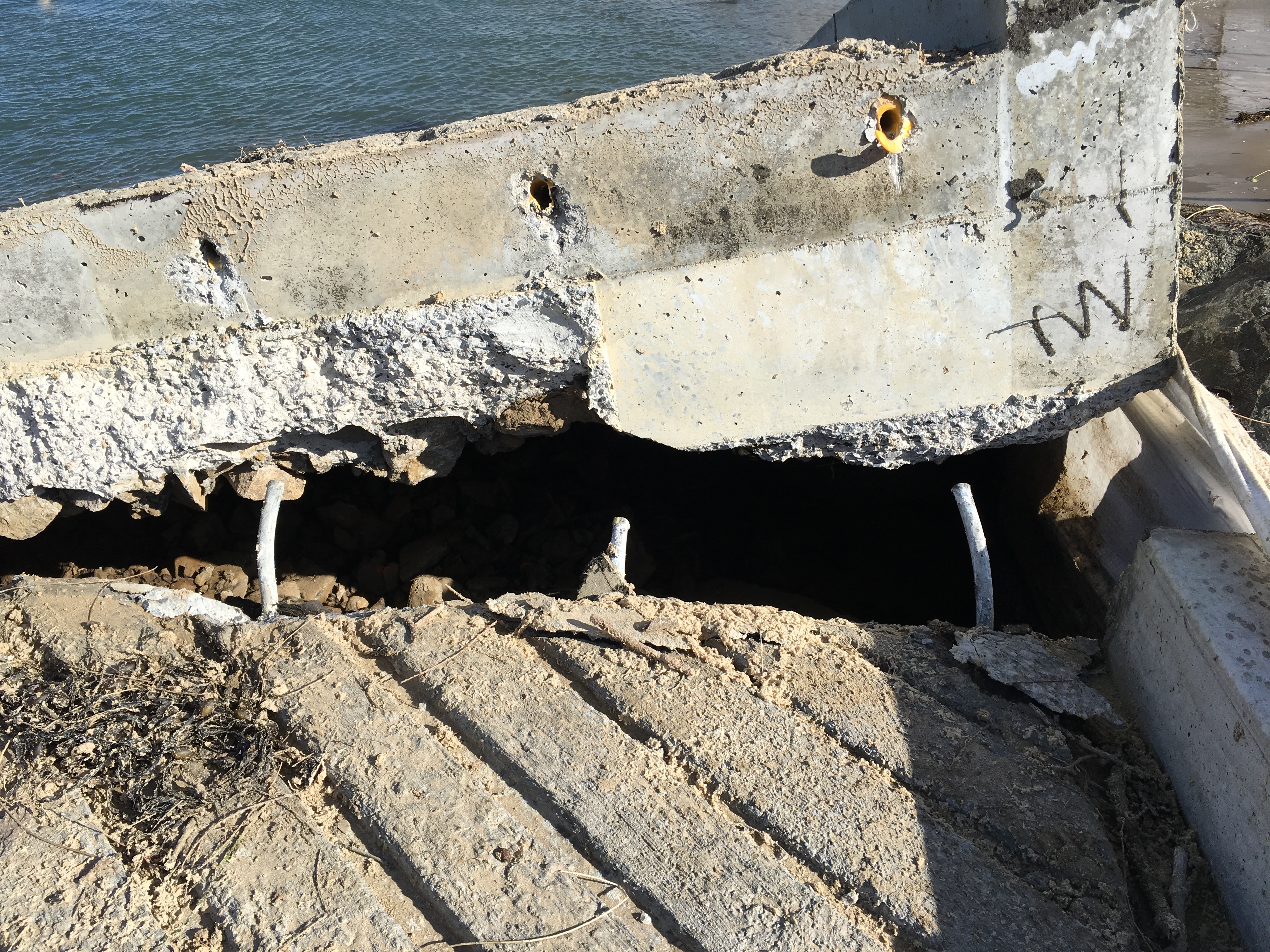
Close up of lifted slab showing dowel sleeves and bent dowels. You can also see elements of subgrade stuck to the bottom concrete layer.
View between the slabs at the expansion joint. No subgrade is visible.

Side view facing back towards the bridge. The edge of the slab is 650mm thick so the slab has dropped at least 650mm at this side.

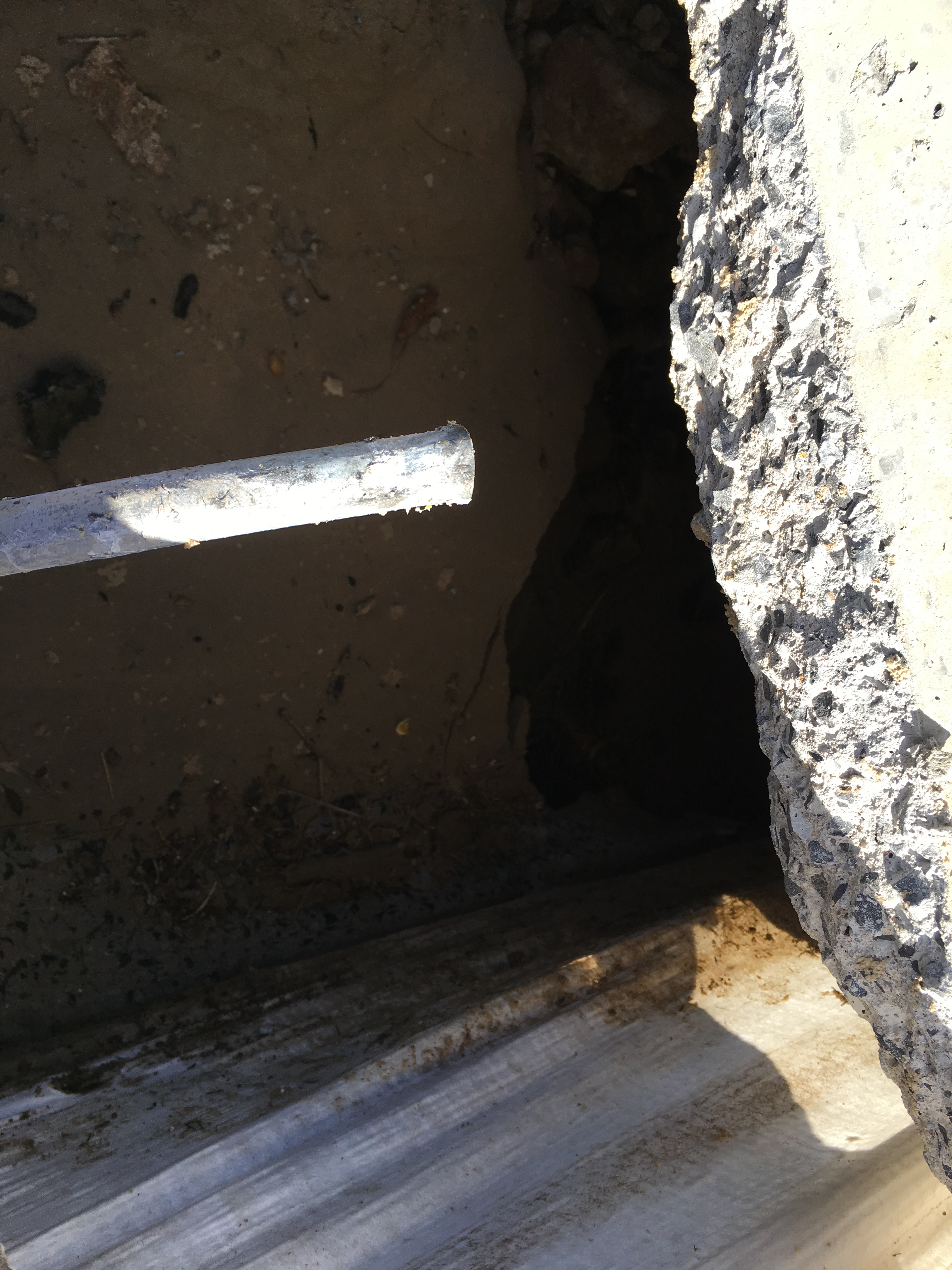
Focusing on the surrounding material. Note the geofabric, washed out material and missing rock armour. Apparently the workers tested the depth here with a 6′ scaffold pole which disappeared below the water surface at high-tide.
Analysis
It seems a number of errors and unfortunate circumstances have combined (swiss-cheese effect) causing a GEO failure. This resulted in structural failure of the expansion joint and serviceability requirements.
Today I was told the project looked at a number of locations to build the temporary boat ramp. The site near the bridge was chosen for speed and convenience despite recommendations not to build there. The sandbanks there are described as ‘highly-mobile sands’ and locals have known them to move frequently move position 10 – 15m. The site is also close to the existing bridge piers as you can see from the photographs. The combination of the piers in the river channel and construction of the boat ramp out into the river will have changed the river flow and velocity at the boat ramp location. This is likely to have increased the localised scour effects.
Typically the mean high tide level is 1.4m above the Australian Height Datum (AHD). Last night there was a high tide surge to 1.9m AHD (remember the seaweed in the photograph above) with water above the expansion joint. The effect of the surge (linked to the recent bad weather) was to undermine the boat ramp slab and scour away the foundations. Greater scour was experienced on one side of the ramp (seaward side) resulting in the slab tilt and shifting. The damage to the expansion joint was caused by the self-weight of the slab.
The drawings show a minimum 200mm subgrade of 50 – 150mm gravel or crushed rock. They also show the scour rock armour was to be 500mm deep and extend 1000mm from the ramp up to the end of the in situ concrete works. The rock armour was to continue around the precast planks in a larger size rock, 1000mm deep and 2000mm out from the precast planks. The rock armour was incomplete (due to be finished this morning) but already questions are being asked about the design and if it had been constructed correctly.
The bad news (from John Holland’s perspective) is that damage to works from tidal events are not insured (are John Holland’s risk) and the site is in the center of town so is bad PR. The good news is that no-one was hurt and the ramp had not been opened for public use.
Conclusion
It is still too early to determine exactly where the fault lies and if closer supervision of the junior engineers would have given a different result. The question is now is what’s ‘Plan G’? Was it an out-of-design event? Should we reinstate or rebuild elsewhere? DO we need to change the design to include sheet pile scour protection? I’m sure it will all come out in the wash (pun intended).
The impact will be significant reworks to remove and reinstate/construct (additional cost). There will also be delays to other project work packages as the existing public boat ramp cannot be closed. This will cause delay and disruption to the piling sub-contractor who will soon start to accrue daily standby charges. The figures make the eyes water! So a quick resolution is in everyone’s interest.
Keep it simple stupid!
We are always taught to KISS in the Army but rarely do we stick to this mantra. Too often it is seen as ‘lacking effort’ to follow what has been done previously and reinventing the wheel becomes a must to be innovative and demonstrate leadership above your peers! The result is mostly a troop of confused chimps trying to understand the intent of the task never mind how to execute it.
As part of the Construction Quality Management (CQM) that USACE use to ensure quality assurance (QA) they employ the Three Phases of Control; preparatory phase, initial phase and the follow-up. The initial phase occurs at the beginning of the task on site and continues each time new work crews are assigned. The follow-up is performed daily to ensure that control established continues. However, the purpose of this blog is my experience with the preparatory phase.
The preparatory phase is performed prior to beginning any work and will review the plans and specification, co-ordinate prelim works, safety and when quality checks take place. How to meet these standards is in the specification and hence my assumption was that this would be a quick final check of a few important details before work was allowed to proceed.
In a pre-construction meeting attended by several experienced project engineers, the client and contractors I was initially concerned that I may be out of my depth having not been a part of the planning cycle. Chaired by the principal contractor (PC), after a few minutes I wondered if I was in the right meetings. I had suddenly either become extremely competent or Americans were a little stupid; given my record I initially went for the latter.
The meeting was about security fencing and the sub-contract (SC) had been awarded to a company who had already been employed on previous National Security Agency work performing well, on time and safely. There were the obvious discussions that I expected about de-confliction with other contractors and site access but then the meeting got ‘simple’.
The PC began interrogating the SC about the fencing and how the corners would be placed, how the connectors would be attached, the testing process and ensuing material was tidy on site. These question would all have been confirmed via the submittals process which itself is monitored by a robust if not longwinded system and therefore already been approved by all parties. Why was the PC questioning such an expert who had already proved themselves previously? At times I thought I could have replaced the SC with Churchill the nodding dog to answer “oh yes” to all the questions. The PC wasn’t asking bigger picture questions; they were questioning the very basic operations of the SC. At what point would the workers put their safety glasses on? Will they use two people when unrolling the fencing to make sure it does not spring back into a roll? The contractor was having to explain a verbal method statement of parts of the work the PC should never need to know. It was akin to a CO confirming where the section commander was going to keep his G1098 tools when on task and if everyone had put 30 rounds in each magazine. I was almost uncomfortable; here was a contractor who has erected fencing at one of Americas highest security bases and the PC was confirming if they were going to wear the correct gloves to handle the razor wire!
How many man-hours was this meeting taking? Are we honestly confirming that the contractor will store the material more than 4 inches off the ground overnight and keep the site tidy! At each stage, stakeholders were jumping in with the simplest of questions to ensure they too got an “oh yes” from contractor Churchill.
But this is the process. USACE insist on it as part of accepting a tender and are rigid with QA business. They have little sympathy for work that is not to the correct specification; it is simply ripped out. Hence the importance for the PC and contractor to get it right the first time: any re-show is at the expense of the PC.
By keeping it simple so that everyone understands and taking the time to “measure twice, cut once” can save days of rework later. The system works if those involved embrace it. The saying “if it’s not efficient, change it” does not exist; there are no promotions for shortening the meeting or changing the process so why reinvent the wheel. Yes, the meeting takes time and is potentially inefficient but the time cost to the PC and USACE is far greater if the sub-contractor delivers a product below quality or compromises safety.
If I had chaired this meeting I would have felt that I was insulting the contractor or at best wasting their time and have felt it necessary to add another dynamic to the meeting to make it worthy of everyone’s time. This would result in ignoring the simple basics and adding confusion to a process they know and find simple, potentially setting the task up for failure. They would then rightly tell me to KISS.
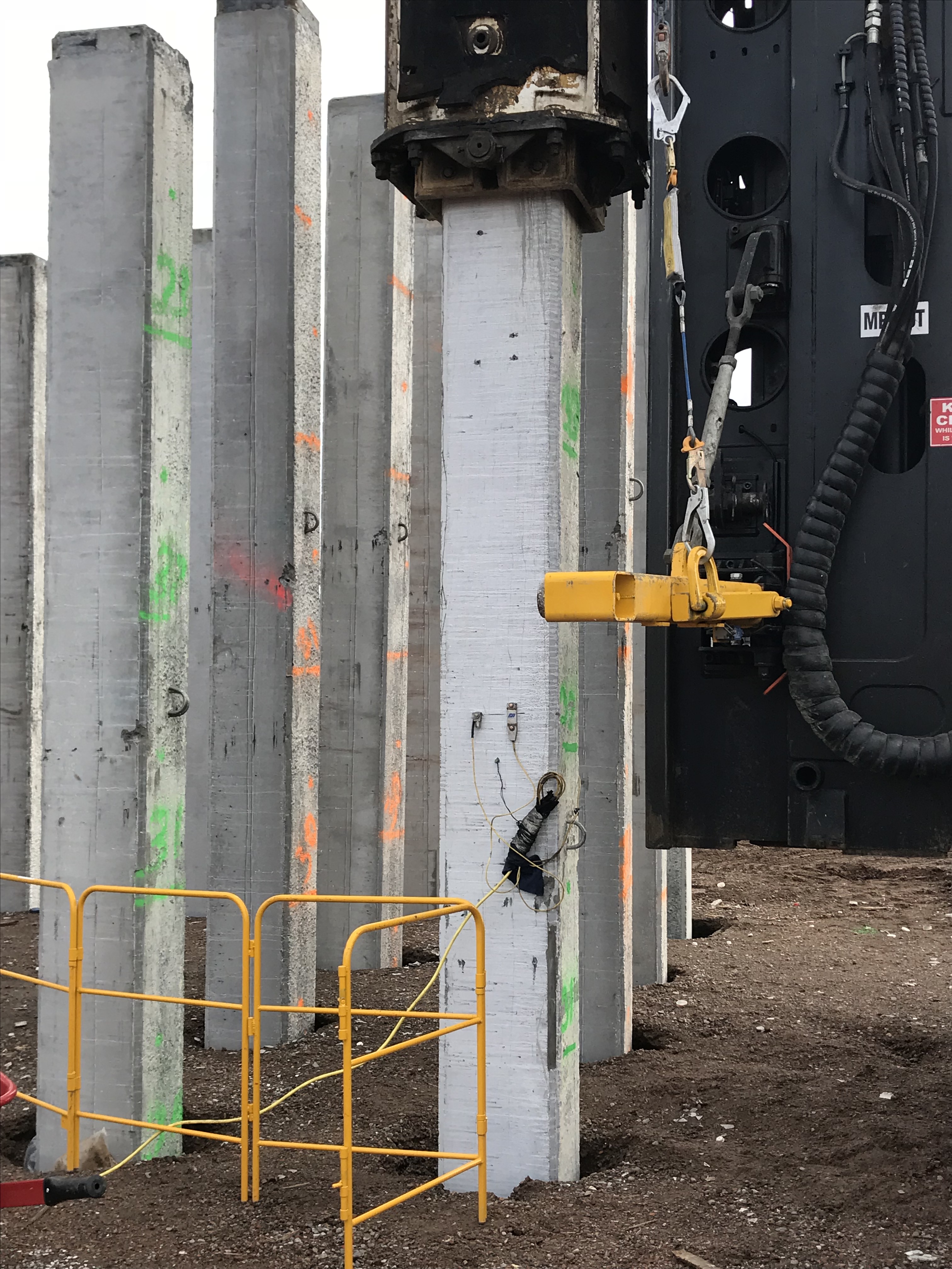
Displacement Piling Precast Piles
G’Day from Melbourne!
As there have been significant delays to construction starting on my site (401), I have spent the last couple of days on a site elsewhere on the West Gate Tunnel Project (403) where they have been installing precast driven piles. I’ve used this time to understand driving process and QA regime in preparation for similar works starting at 401.
Of interest has been the rejection of several precast piles by the Principle Contractor (CPBJH JV). Piles, as per a previous post of mine, have been cast by the piling subcontractor as part of a Design & Build Contract. I have also taken keen interest in the testing of piles and the process of restriking.
With this post, I hope to provide those on attachment with no involvement of precast concrete structures or driven piling operations with an insight to what I have learnt, and maybe get some thoughts?
Rejected Piles
Precast piles, under VicRoads (VR) 610 specs, must have a Class 1 finish. This is a durability requirement given that piles are subject to aggressive subsurface conditions. On 403, and undoubtedly an issue we will forego at 401, several piles have been rejected due to surfaces having excessive ‘blow holes’; a result from the entrapment of air during casting. The standards we work to state that blow holes over 15mm in diameter and /or 5mm in depth must be repaired prior to installation.
The issue we have is that there are no approved repatching procedures for the project. This means, under the PSR, that piles cannot be repatched and must be rejected; a cost risk held by the subcontractor but one that will delay CPBJH JV further. I’m amazed that no procedure exists and, as you can imagine, there are a lot of people scrambling around to get one in place. Simple? It would appear not. Several procedures have been submitted for approval but, after review, have all been rejected by the IREA (the Client’s third-party auditor) for being non-compliant with the PSR.
What surprises is me is that the subcontractor hasn’t just had a go at patching at their yard off the cuff given that this is their trade? Clearly this would result in a NCR (Non Compliance Report) but possibly worth the risk for them? Considering they have delivered the piles to site and are cracking on (ignore the pun) seems to me that they planned to install them anyway, and hope no one would notice? As can be seen in the picture below, the extent of some blow holes seems very minor (see pictures below). I’d be interested to know if anyone else has seen this, has experience in the matter or would have a solution that doesn’t involve weeks of submitting approvals and replying to comments prior to acceptance?


Testing and Restriking
As per VicRoads Spec 605 (Driven piles), the first pile driven in each pile group is tested and the ultimate capacity is determined in accordance with the formula used in design (Hiley Formula). The test then determines the driving set for each pile group by correlating the set with the driving system and the designer’s requirements for the pile test loads (these must be demonstrated on the design drawings). All piles within the group are then driven to a set that does not exceed the driving set determined by the first pile.
The method of testing for this project is Dynamic Load Testing (aka dynamic loading). Dynamic load testing is a method used to assess the bearing capacity of a pile by applying a dynamic load to the pile head (i.e. dropping a hammer/weight on the pile from a set height) while recording acceleration and strain on the pile head.
In Australia and Victoria State, Dynamic Load Testing, under AS2159-2009 and VicRoads 608, is sufficient to prove geotechnical capacity of a pile. The foundation bearing capacity results obtained with dynamic load tests, from research, appear to correlate well with the results of static load test, hence they are an approved method here. Piles designed to take large geotechnical design loads and are integral to a structure, are use static load testing as a preferred method; simply because they are more accurate.
A restrike of piles then must be conducted, under VicRoads 605.08, on 10% of piles in the group, not before 24 hours after driving. The idea behind this is to assess whether ‘set-up’ or ‘set-down’ of piles has occurred (i.e. pile capacity has increased or decreased over time). It appears that the most accepted reasoning for ‘set-up’ occurring is pore water pressure related (Q the many hours of John drilling Mr. Terzaghi at us!).
Effectively, as driving occurs, pore water pressures increase around the pile, reducing the effective stresses in the soil and thus the capacity of the pile. The idea of the 24 hours (minimum) time between end of drive and restriking is to allow time for these pore water pressures to dissipate back to pre-driving levels (though I’m not sure how a prescribed time can be used given that, if I’m not mistaken, dissipation of pore water pressures is a function of the soil characteristics?).
In total, 2 piles are tested per group with a restrike. The 2 piles selected are the initial pile that was tested and the pile that recorded the highest set; for those unaware, set refers to the distance the pile moved per the last 10 blows – about 32mm in this case. This ensures the pile mobilising the least resistance in the group during driving is tested (i.e. the pile with least geotechnical capacity – theoretically).
The requirement to re-strike comes about for two reasons. Firstly because, while across my site (Zone 401) it is expected that piles will gain capacity over time, it is possible that the soil might either relax or that the piles heave, resulting in pile capacity deterioration, and the easiest way to confirm that it isn’t occurring is by completing a restrike test. Elsewhere on the project (Zones 402 & 403), restrike is being used to demonstrate that piles are actually gaining capacity over time (set up), where the ground conditions involve deep profiles (31m whereas 401 toe levels are designed to 12m) of cohesive soil which will be ‘failed’ during the pile installation process and will then ‘remould’ over time to provide resistance in the form of skin friction.
The second reason is that it is required under VicRoads 605.08, which states that restrike of driven piles must occur, and not be 24 hours.
When conducting the restrike, I noticed that the Testing Engineer did not start by conducting the test with the full dynamic load (in this case a drop height of 1.5m), instead he started with 0.4m and then struck again at 0.6m before striking at 1.5m; as note, the operators messed this up and accidentally dropped the first strike at 0.9m. The reasoning for starting small is to check the pile does not crack/damage under the stress induced from the dynamic load. Clearly, if superficial cracking/damage can be seen to occur from a lower energy then they will not continue with full drop height. This I suppose is a weakness of the Dynamic Load Test in comparison to the Static Load Test – More chance of damage to piles from the fast impact loading.
PDA equipment calculates the velocity and force signals obtained from accelerometers and strain transducers attached to the pile during driving (only attached to piles being tested). Two identical accelerometers and strain transducers are attached close to the head of the pile on opposite sides and diagonally across; this allows for a better average of results.

The PDA was used to record, digitize, and process the force and acceleration signals measured at the pile head. These signals are used to estimate static capacity using the ‘Case Method’, a simplified field procedure for estimating pile capacity. PDA tests only provide direct measurements for the forces and motions applied at the pile head and are sufficient on their own and the static and dynamic soil parameters and distribution of forces over the pile shaft and toe are not directly measured.
To account for this, a CAPWAP analysis is conducted by an offsite, independent, Testing Engineer. To verify the static component of pile resistance, the CAPWAP analysis is performed on field data from a selected representative hammer blow from the PDA test record. CAPWAP analysis resolves three unknowns: the internal pile forces, pile motions and external forces. It is far more detailed than a PDA test. However, it requires expertise and experience as soil characteristics and ground water must be entered accurately; this requires judgement of the engineer.
I’ll look to get hold of the CAPWAP results and consult with the testing engineer to see how the design, PDA and CAPWAP results compare once the piling has started at 401 to further understand!
On another note, the weather is looking much better back in the U.K. at the moment – you can’t stay on the beach past 5pm now ….
