Archive
Steel Fibre Lightweight Reinforced Concrete
First patented in 1874 and used extensively for bomb damage repair to airfields in WW2, SFRC is a well established construction material with a number of potential benefits, especially when used in situ to form composite slabs on profiled steel decking.

Steel fibres are graded I – V according to BS EN 14889-1
Steel fibres are often used to replace the steel mesh or fabric reinforcement in slabs. As well as composite slabs, they are used extensively in ground bearing slabs and pile-supported floors and can replace much, if not all, of the traditional welded reinforcement.
By mixing steel fibres into ready mix concrete at the batching plant you can avoid the need to pre-place traditional reinforcement. This gives considerable time and H&S benefits (manual handling, cutting, etc) as well as some secondary benefits such as reduced numbers of deliveries to site and less demand on crane time to lift bars and mesh into place. You are also able to better guarantee distribution of reinforcement through the depth of the slab, removing the risk of misplacing reinforcement within the depth of the slab.
On constrained sites (like mine) hook time is at a premium and there is limited lay down space for material. In addition, the build sequence only allows us to pour slabs once the two floors above have been steel decked to provide some measure of overhead protection (i.e. we cannot pour concrete on L01 until L03 has been completely decked by the steel erectors). On the other hand, once L02 and L03 are fully decked we have no way of craning our bars and mesh onto L01 as the lay downs will have been covered over. As a result the concrete contractor has to design, call-off , deliver and bulk lift all reinforcement for L01 eight weeks before he is able to access the level to place the reinforcement, run out pump lines and pour the concrete.
It seems to me that a large amount of this work could be rationalised through the use of SFRC in the concrete mix so I am wondering why it hasn’t been specified on this project. One issue could be that in order to provide a resisting stress under tension you need strain in the steel – in traditional (in plane) reinforcement the strain required is very low but in randomly oriented fibres there could be greater strain before the required stress is realised, resulting in higher deflections. Compression performance should be unaffected.

Steel fibres in a handful of the grey stuff
This project has 11 different composite slab combinations but the ‘generic’ case is a LC30/33 (Lytag) concrete on a profile sheet deck. The reinforcement is a H12 bar in every sheet trough (for fire resistance) and either A193 or A393 mesh in the top. Where this mesh is for crack prevention only I can’t (yet?) see why it couldn’t be replaced by fibres. The larger mesh is specified where the slab is designed to transfer diaphragm loads through the structure so there is more to be looked into there. I don’t propose replacing the fire bars.
Anyway, this is very much a new thought which may not go anywhere but I would welcome people’s thoughts or feedback from anyone who has seen this in action.
Oh, and do we still use it for airfield damage repair? I don’t remember using it.
The good ideas club
The Woking parking complex has now been demolished to ground level and the strip out of the ground floor slab and foundations has begun.
The current foundations are large shallow strip foundations at approximately 7m in width, 1.5m depth and 70m in length. They are heavily reinforced and approximately 1.5m below the ground force slab.
The structural designer has planned for the entire removal of the foundations to make way for the piles and pile caps that will be replacing them. However, ever the opportunist our demolition subcontract has had the idea to only remove the sections of the strips that would collide with the new pile caps to save time, money and waste. His argument also that the hole in the foundation would save time on having to build and strike formwork.
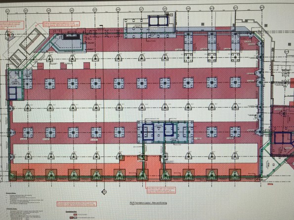
The drawing above shows in pink the existing foundations with the proposed. It sounds perfect on paper, but the question remained would it really be easier to precision cut out sections of a foundation at depth rather than dig the entire lot up.
The first challenge was the depth. The batter needed to get down to that depth is around 1.5m. The centre point of the proposed pile caps are 7m c/c and the caps themselves are 3m wide. If you excavate this cap with the batter that does not actually save you much in terms of excavated fill. It also means your site is 2/3 hole and 1/3 trackable access.
Secondly was the rebar. Bulk removal with a leading edge would simply mean using a muncher to rip up the rebar. However the process of leaving holes in the foundations requires a breaker machine followed by a bloke hot cutting the rebar instead. A trial foundation was dug on site this week and the whole process took 2 days for one pile cap. 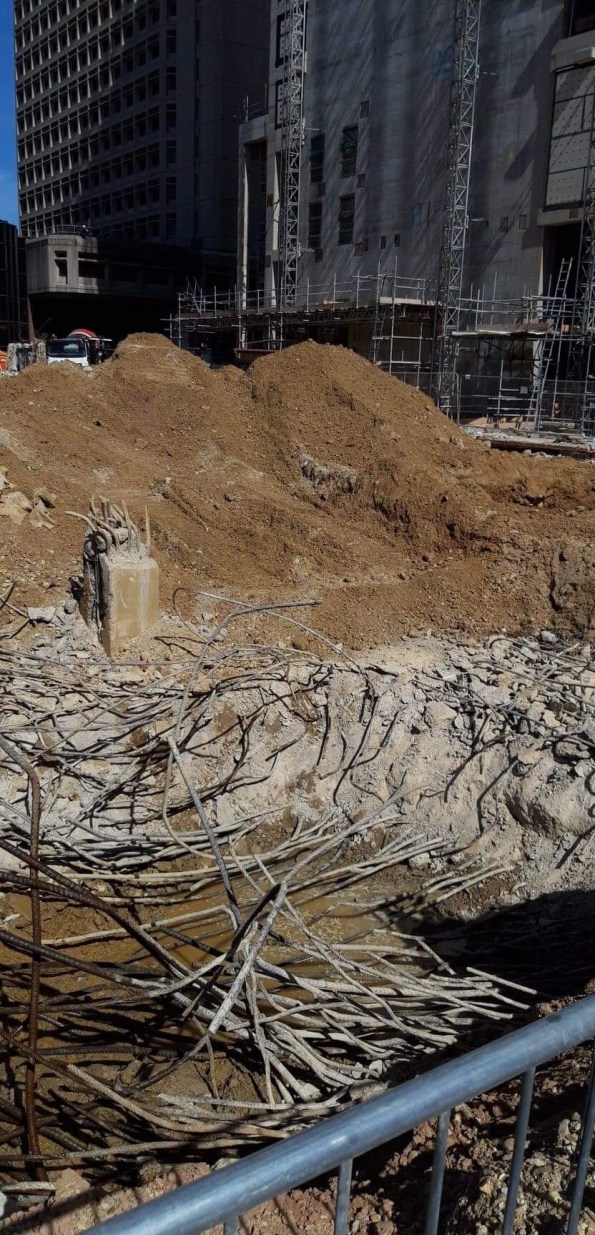
the photo above is the trial attempt to “neatly form a hole in the existing foundation”.
In my eyes value engineering has its place and innovation should be considered, but there is a time and a place and I don’t think it worked this time. As the PC we were all sceptical but allowed the SC to trial it, they can chose whether they persist with this methodology but they will not receive an instruction from us to permit them any further allowances.
The importance of definitions
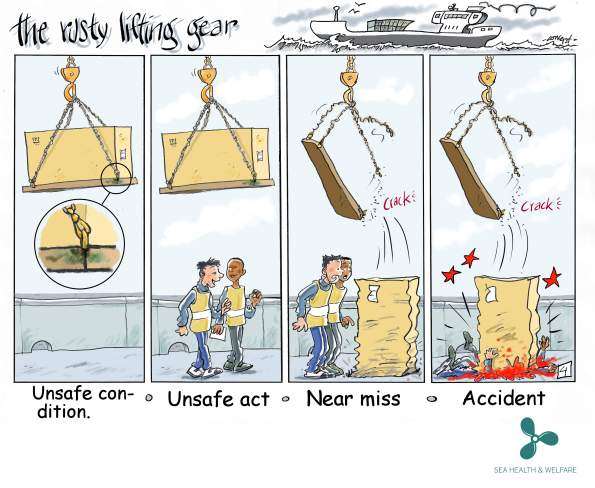
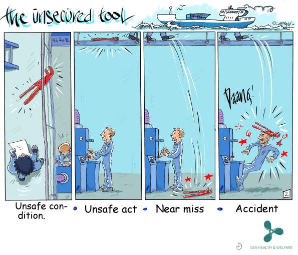
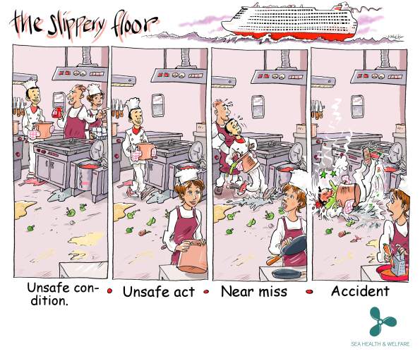
Following a few recent blogs regarding H&S incidents I thought I’d share these little cartoons we found depicting the different terminology for various incident types.
The first image seems particularly relevant for both Mark’s and Al’s recent experience with lifting equipment. From reading the blogs it sounds to me like Al’s site experienced and unsafe act when a worker was seen under an unsupported load. Mark experienced an unsafe condition (the poor slinging technique) which led to a near miss (the thing actually fell but no one was hurt).
While of course all of these incident types should be properly addressed, and all have degrees of severity within them, the terminology used can be quite important.
Take, for example, our ever-troublesome scaffolders who failed to properly enforce an exclusion zone on a public-access pavement beneath their work area. They were spotted and the situation was corrected but was this a near miss? Nothing was dropped onto the pavement and no one was injured but the potential was there. This was reported as an unsafe condition (working overhead without edge protection). Had it been labelled a near miss (with the potential to impact the public) we would have had a world of problems.
This may sound like opportunistic word play but it is an important delineation. From a safety point of view it was a very serious occurrence, and was treated as such by all involved, but contractually the wording is vital, similar I suppose to John Holland’s 1P rating in addition to the strict H&S term. The irony of the situation is they were up there erecting a scaffold fan to protect pedestrians from falling objects!
A great deal of fallout resulted of course (revisiting method statements, tool box talks, safety briefings, etc) but the point of this blog was the importance of definitions in contractual communication, and not just in H&S.
Precast pile de-heading
Hi all! I just thought I’d put up a quick post about a new technology/process I have been involved with this week.
Having almost completed the first stage of precast pile installation on my site, we are ready to start de-heading piles in preparation for pile cap construction.
Pile de-heading is recognised as a risky activity within the construction industry. Eventually, approximately 4500 precast concrete piles (13,500 individual pile segments when considering spliced piles) will be installed across the east zone of the West Gate Tunnel Project. Given the inherent risk of the deheading activity, a concerted effort has been undertaken to investigate the safest ways to undertake each stage of the process.
A lot of thought and consideration has gone into the different methods available to remove or reduce the people and plant interface, a High Risk Construction Work Activity under Victoria Worksafe (Vic State version of HSE), which are activities involving people working in close vicinity to items of plant.
De-heading or pile-trimming refers to the practice of cutting piles to a pre-determined level after they’ve been driven into the ground to the required depth or capacity, which is around 30 metres generally across the East Zone and 12m-14m across the scope of works conducted thus far on my area of responsibility.
Traditionally a number of methods have been used to perform the de-heading, including workers using hand-held ‘demo’ saws in combination with plant to support and remove cut sections. Typically, this activity involves a crane holding the pile, while workers saw cut the concrete and corner longitudinal reinforcement This involves a lot of people/plant interface and other safety risks such as: falling concrete segments, potential silica dust inhalation, injuries associated with repetitive tasks (such as ‘White Finger’ vibration injuries) and exposure to loud noises.
After investigations into safer options with the piling subcontractor ‘Keller’, it was decided a much safer method for these works was to use an excavator with a de-heading attachment.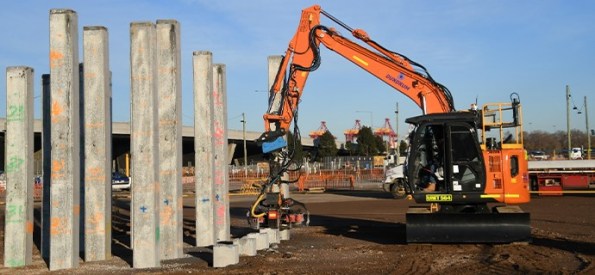 How does it work?
In simple terms, after the de-heading attachment is connected to an excavator arm, it connects to a pile and its blades cut through the reinforcing steel at each corner. Another excavator then moves in, grabs the pile and snaps it at the cut-off point and then carries the excess length of pile directly to the waste skip for removal. This technology is not entirely new and has been used before in Australia, but rarely, as it suits projects with a large-scale piling requirement, such as ours due to the increased costs.


The main benefits of using this pile-trimmer method include:
1. Safety: as this process is undertaken via an excavator, it completely removes the people/plant interface.
2. Environmental improvements: it’s quieter than other options, such as jackhammers, while dust dispersion is mitigated as the device ‘self-doses’ water during cutting.
3. Increased productivity: this method is quicker than other de-heading methods, meaning increased cost of plant/technology can be saved against traditional methods through saving in time and project schedule.
4. A better result: the end of the cut-off pile is ‘cleaner’ than it would be using other methods.
What’s next after the pile de-heading?
unfortunately, the plant trimming method cannot be used down to the final cut-off level of the pile. After the piles have been trimmed to the correct height (300mm above the surface), the next step is known as breaking-back the pile. It involves digging around the piles to the cut-off level, then chipping away the concrete to exposing the reo bars.
This is another process that will be performed mostly by excavator, with only minimal use of a jackhammer at the final stage, to expose the reinforcing steel. Again, reducing the risks to workers on site.
This method of pile de-heading is a big step forward for safety across the industry and will likely see increased use in the future, especially with Tier 1 Contractors.
What is a Soft Start?
A few weeks ago we had two notifiable incidents occur within 24 hours. Fortunately, there were no injuries but both were classed as the most severe category (1P) under the John Holland reporting system as they had the potential for workers or the public to be killed. Details about the two incidents are included at the bottom of the blog but for the timebeing, I want to focus on the procedure to restart works.
What interested me most about the incidents was the Project Director’s response. After conducting John Holland’s reporting procedure and informing the Client of the incidents he closed the site. The next working day all directly employed staff attended a meeting where the incidents were discussed in detail. The bottom line was that safety is always the priority and that these incidents were a ‘free pass’ as no-one was injured but we needed to to do better going forward. He identified 5 key areas of concern:
- Services
- People and Plant Interaction
- Lifting operations
- Temporary Works
- Pubic Interaction and Traffic
Following the meeting all construction managers, engineers and supervisors were tasked with reviewing their procedures, Safe Working Method Statements, Task Risk Assessments and work permits for their respective areas. The workers arrived mid-morning and were involved in the process. The afternoon consisted of site health and safety inspections to identify areas for improvement. This allowed improvements to be made to the existing procedures, method statements and constructions site set-up. A feedback session was conducted late afternoon for the directly employed staff. No project productive works were completed that day.
The next working day a ‘soft-start’ was conducted which was a gradual return to works with the identified changes implemented under closer supervision from the supervisors and engineers. For areas requiring additional time to review their procedures and documentation, the Project Director supported the delaying of the ‘soft-start’ in their area for as long as was required.
What impressed me about the way this was handled?
- The Project Director was clear where his priorities lay and drove the process.
- It generated increased involvement and attention from the construction managers and senior engineers that I hadn’t experienced previously on site.
- The time to pause and review was critical.
- Input and empowerment of the workers was essential.
- The Project Director was willing to bear the cost of a non-productive day and liaise with fixed price contractors as required to ensure their buy-in.
- A re-focus on the basics. John Holland has a set of Global Mandatory Requirements (GMRs) that are used to manage key construction risks which are used when planning activities. These headings formed the basis of the review. On site we have a handy booklet but the GMR sub-headings can be viewed here.
I’m interested to hear if anyone else has experienced anything similar on site. If so how was it handled and what did you learn from it?
Incident #1:
The first incident was a dropped load from a gantry crane at the pre-cast yard. A worker was using a gantry crane to turn over a pre-cast mould bulkhead to weld plates on both sides. There were a number of factors that caused the incident in a ‘swiss cheese’ scenario:
- The worker operating the gantry crane is a dogman (rigger or slinger in UK/military terminology) but had not been used much in this role previously on site.
- The worker had not operated the gantry crane before but the supervisor thought he had. (Following the incident it has not been possible to determine if the individual completed the on-site training from the gantry crane supplier as no record of the training was maintained).
- The worker was not aware of the designed lifting points on the bulkhead.
- An engineer was asked about the weight of the lift. The engineer remembered lifting a bulkhead previously so stated the weight he remembered. No plans were checked and he estimated the weight incorrectly.
- The worker decided to use soft-slings to lift the load. He was aware of the potential for the metal edges to cut into the slings so used rubber to pack the metal edges against the slings.
- As the load was picked up the rubber packing moved.
- The soft-slings were cut/snapped on one side of the load resulting in a dropped load onto the foundation slab.
Following the incident works were halted, the load was made safe and the incident scene preserved. Senior management were informed and external bodies notified. The senior management team used a technique called 5 Whys? (similar to the combat estimate and asking ‘so what’) to get to the root causes of the incident. A number of areas were identified that could have prevented the incident from occurring. Examples include:
- A bespoke and accredited gantry crane operators course.
- Identifying designated gantry crane operators and alternative operators.
- All precast lifts are identified at the morning pre-start and discussed with the team.
- Two engineers are required to check the drawings and calculate the weight of each lift independently. Their assessments are compared prior to conducting the lift.
- The use of soft slings is now restricted at the precast yard with a permit system adopted.
- More emphasis has been placed on ensuring the correct mix of qualifications and site experience (SQEP) across the work crews.
- Giving nominated personnel responsibility for tasks such as maintaining designated work zone signage.
These have now been incorporated as new processes or procedures at the precast yard with the Safe Work Method Statements and Task Risk Assessments updated accordingly.
Incident #2:
The second incident related to an excavator which hit an elevated LV cable when tracking from one working area to another and pulled it down to ground level. This was classified as a 1P event as the pylon also had a HV cable which was not disturbed. Again there were a number of factors that contributed to the incident:
- In preparation for the weekend site closedown, the excavator operator was instructed to conduct environmental controls in a different area of the site.
- The excavator driver was guided by a pedestrian spotter under the power cable to access the other area of the site and completed the environmental controls.
- The excavator operator returned to their original working area but was not guided under the power cables.
- The operator was aware of the power cables but lost sight of them as he was passing under the cables resulting in contact with the LV cable.
A similar incident review process was carried out and the following root causes identified:
- A change in planned activities (over here they call it Change Management*). This is considered to be a contributing factor in most site incidents.
- No ‘goal-posts’ or overhead power lines signs were displayed. The signs would have had little effect as the operator knew about the power lines but the ‘goal-posts’ might have given warning that the excavator’s arm was too high.
- There was no requirement to track the excavator across the top of the embankment. Traffic barriers have now been installed to prevent access.
- The operator failed to adhere to the project spotter procedures when operating near power lines.
*This is different from the use of the term on Project ANEMOI where it refers to the deliberate/planned change of the design following a formal process.
H&S File – to be or not to be?
A relatively quick update from Gatwick: The new Pier being built for the large A380 aircraft is approaching the end of the primary steelwork installation. Prefab passenger bridges connecting the building to the rest of the terminal have also craned into place. It is during this installation a fairly serious H&S incident was observed (see pic below). This shows a worker underneath a suspended passenger bridge frame. Under LOLER regs states there should be ‘a secondary means to support the load’ which clearly isn’t really fulfilled by the forklift. If the frame had been rested on trestles or props the risk could have been minimised. In short if one of the slings fail then there is nothing to stop the load injuring the worker. Clearly the worker was immediately informed of this and a near miss raised.

I have also been the client lead for some GI works at other site at the airport in preparation for ground works (aircraft pavement replacement and pile foundations) for the Pier 6 extension main build. These small packages of works have been separately contracted out to framework contractors who are well established at Gatwick. At one site, an aircraft stand, the GI involved concrete core sampling and in-situ testing of the subbase layer with a DCP. The GI works are now complete but the principal contractor seems to think that a H&S file is required. Firstly I’m not sure why they are raising this as it is prepared by the principal designer. Under CDM a H&S file is required where there is more than one contractor involved. There were two contractors involved on the works: the principal contractor (who also cored the PQ concrete to reach the subbase) and a subcontractor who completed the sampling and testing. However, I’m still not clear if a H&S file is needed in this instance. The coreholes were reinstated with a bentonite solution and I can’t see how there would be residual risks, as-builts (maybe corehole locations?) or maintenance requirements to document?
Clearly a H&S file will be delivered as part of the overall Pier 6 project by the principal designer, so this package of works would form part of that. The GI report would be delivered as part of the Pre-Construction Information for the groundworks contractor.
Looking forward I will be getting involved with the ground works contract for the main Pier 6 extension.
Melbourne is Settling!
I just thought I’d share a quick blog on some interesting settlement issues I noticed walking through the ground level storey of a multistorey carpark last week. Whilst passing through, I noticed some serious concaving of the pavement between column rows, creating a wave like effect across the whole car park. On closer inspection of the columns, I noticed that the top of concrete foundations were protruding out of the asphalt surface. The reason for these ‘dips’ in the carpark are due to some very noticeable settlement of the underlying ground.


Across the wider area is a varying depth of Coode Island Silt (aptly named after the area known as Coode Island in Melbourne where I am working). Having done some research into the geology for TMR 1, the existence of this silt layer is not surprising, considering Melbourne was found on a huge swamp along a large river basin.
The Coode Island Silt is a large alluvial deposit along what is known as the Yarra River (main waterway passing through Melbourne) Delta. It is a highly compressible soil which is only lightly consolidated and has a high voids ratio, making it very prone to settlement and creep when stressed – think back to the graph plotting voids ratio against effective stress; no stress history on a soil with a high voids ratio will lead to high strain. This limits the use of shallow foundations across Melbourne, making piled foundations a favoured solution.
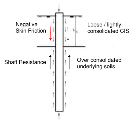
The inherent risk of both primary and secondary settlement is high for foundations formed in this soil and downward drag (i.e. negative skin friction) presents significant risk for deep foundations. From researching the GDRs produced for my project, downward drag from the Coode Island Silt consolidating is expected in less than 3 years. The forces induced will be a function of the rate and size of settlement at each pile location, the skin friction induced along the pile shaft (depth of the silt varies significantly across my site) and vertical movements under live loading; Negative skin friction is not considered for ULS design due to piles settling relative to the surrounding soil – as previously taught in Phase 1. This means it must be considered in SLS design to ensure long term settlement does not have negative affect – or cause issues like those seen in the carpark!
I hope this is of some interest to those who might not be working ‘in the ground’ and highlights the importance of the estimating stress history of soils.
Bigger is better?
Having got to grips with the EDF Hinkley Point C (HPC) Nuclear New Build (NNB) programme now I can tell you that every day it blows my mind as to the scale of what is taking place. Everything is in excess. For example, it was decided that if the reactor dome could be constructed away from the reactor common raft, before being lifted into place when on completion, it would allow multiple works packages to run in parallel, saving time and therefore cost. But how do you lift something like that into place when it’s ready? Easy… you use the Sarens Super Crane!
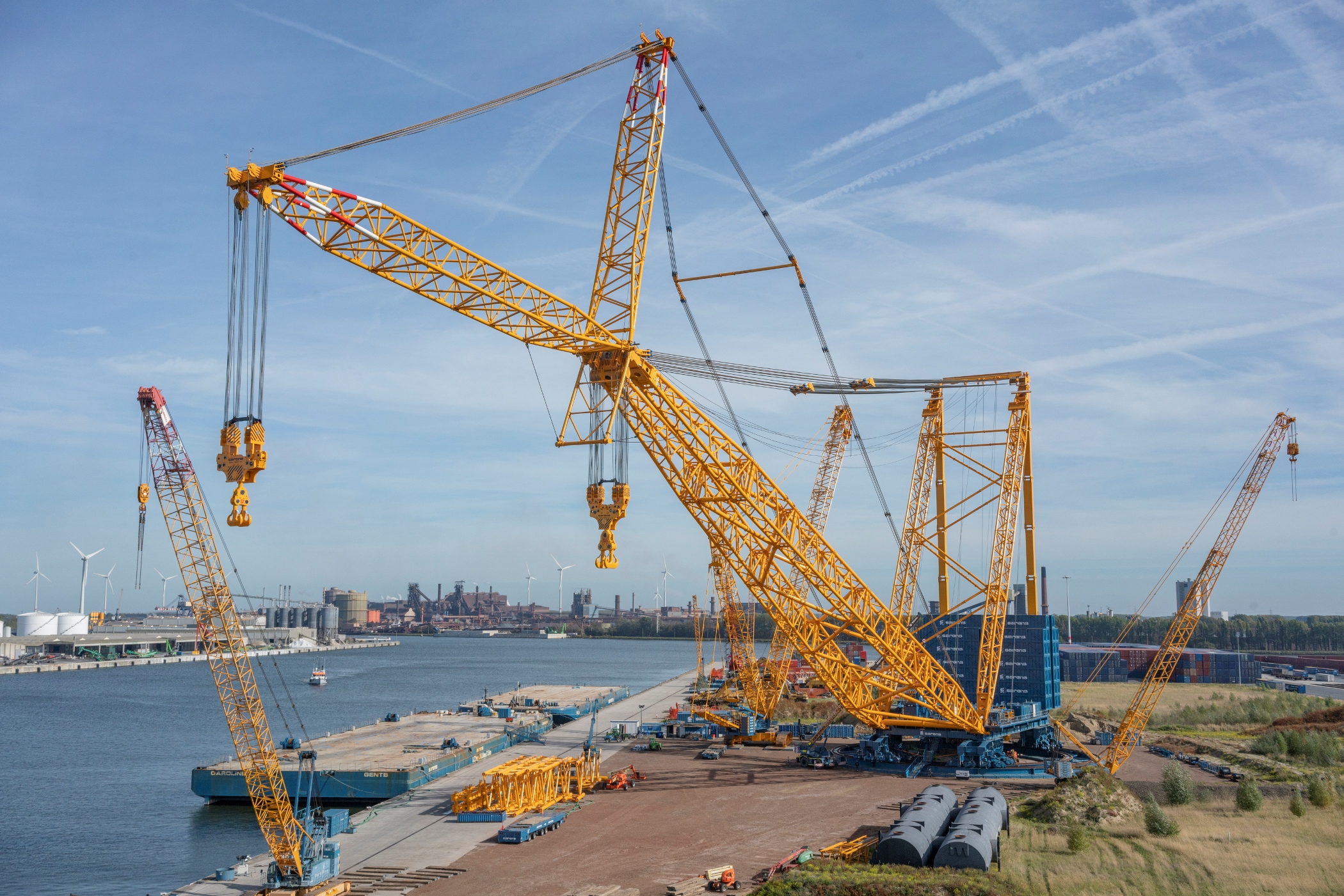
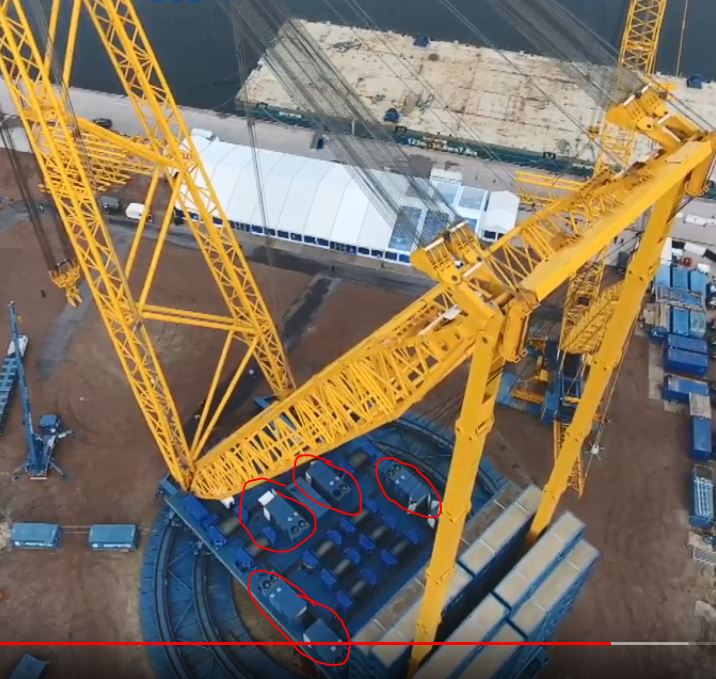
The Sarens SGC 250
The crane has a maximum load moment of 250,000 tonnes, allowing it to lift 5,000 tonnes at a radius of 50 metres. Even at a larger radius of 100 meters, it can lift 2,000 tonnes. Although at 100 metres, it wouldn’t stretch far across our site – so its going in on rails to transit between 3 separate 360° slew points.
Its difficult to find a photo perspective that does it justice but the Sarens link here does a pretty good job; https://youtu.be/BHwbu8iWrBo
Update in response to comment: Power is supplied ‘on-board’ using gen-sets…
Ramifications of Past Decisions
This weekend saw the first of 15 consecutive weekend works, caused by a single decision early on in the project.
Early on in the project when the design for the precast elements was not complete, a decision was made to start piling. This was due to high standing costs for the piling barges and instructions from the client to start work. This meant that the first row of pre-cast was not able to be placed.
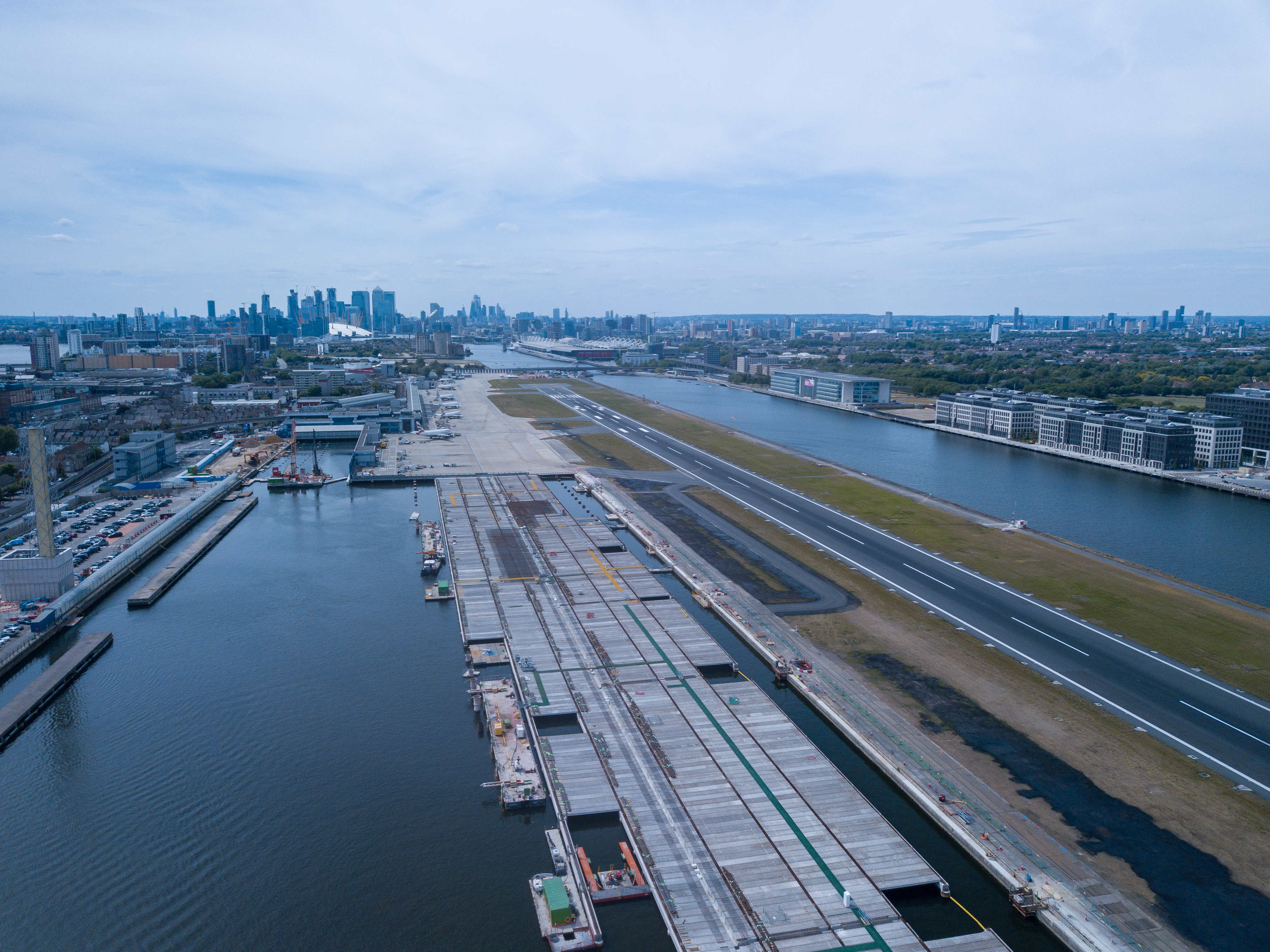
An aerial view of the deck showing the missing precast between the dock wall and the new deck
The solution was bringing in a 450t crane to lift everything into place. This is achieved during the weekly 24hr airport closure between 1200 on Saturday to 1200 on Sunday.


This 24hr possession enabled the installation of 8 beams…. I question whether the management are ruing their decision many months ago.
It will be interesting to see whether BAM can claim the full costs of this back from the client, stating that this is due to a PMI telling them to do so!
