Archive
Finding the ‘G’ spot – High Pressure Dilatometer
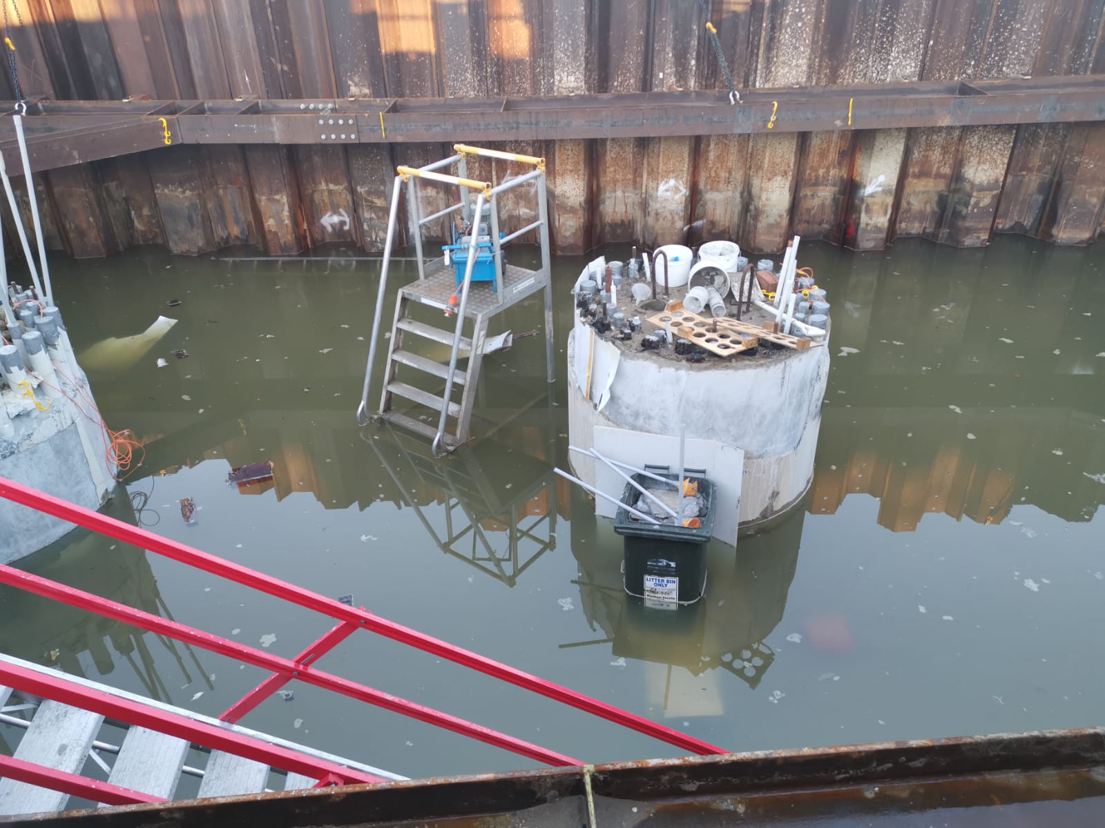
I’ve been recently managing ground investigation works at a car park that will become a temporary construction site for four large steel frame modules (Approx. 50x50m). The GI is for the temporary foundations which will support these modules. The cores that have been found on site so far have revealed Weald Clay Mudstone at the depth of the proposed foundations. Recently I observed the use of a pre-bored High Pressure Dilatometer (HPD) which I had not heard of before. I thought this might be useful to explain a bit further. It’s an unusual but accurate method of finding horizontal soil strain ‘ε’ and shear modulus (G) in-situ instead of laboratory triaxial tests. It’s used much more commonly in France and other parts of europe but I’ve been told it is increasingly being used in the UK. It was developed from the Ménard pressuremeter, which is still used but is less accurate. It can only really be used in fine grain soils and most rocks, though problems are encountered in limestone where there’s lots of flint. The device isn’t useful in coarse grain material due to the low plasticity of the soil giving inaccurate results. It works by placing a cylinder at a certain depth with a membrane surround (see image below). The membrane inflates to apply pressure against the soil, where a number of sensor probes measure the pressure of the soil. This pressure is plotted onto a graph against the length of membrane expansion.

It comes in 3 different types:
- Self-Boring – Has the advantage of being more accurate as the dilatometer fits the hole much better and there is less disturbance of the soil, providing more accurate results. Not viable where there are layers of coarse grained material that can disturb the borehole or where rock is encountered.
- Push type – Similar to self-bored, but the sensor is driven into the ground. Has similar advantages but is limited to soft fine grained material such as clays. This can raise the stress of the surrounding soil, limiting the data you can get from this method. It is however much quicker.
- Pre-bored – A borehole is made to the appropriate depth and a dilatometer inserted into the pre-formed hole. The main advantage of this is that it is more versatile and can be used in a number of different type of soils. Best used in rock and stiff clays. Cores can also be taken during boring enabling lab testing of samples. Less accurate due to soil disturbance during boring.
A graph of average readings from the car park soil can be seen below showing cavity pressure against cavity strain. You will notice that there are a number of loops on the graph not too dissimilar to the stress/strain curve. The HPD operator expands the membrane until the pressure begins to level, and then releases some of the pressure, allowing for the soil to recover. The pressure is then reapplied causing an ‘elastic rebound’. This is usually done three times to give a spread of results. As I understand it is the average rate of this elastic rebound that can be interpreted to find ‘G’. The test is continued up to a point where the pressure begins to level off. It is not so easy to see in this image, but the individual sensor results show a gradual levelling off. I was told by the operator that they usually stop the test at this point as there is a risk of membrane rupture. As each of these cost about £80k this is understandable!

I have been told there are relatively few GI specialists in the UK who can carry out this kind of test and even fewer who are certified to interpret the results. That said it seems this is a much more accurate way of finding undrained soil properties from in-situ testing against more empirical methods such as soil classification properties against previous data. It may be particularly useful on sites where there is little empirical evidence. It is also more accurate than triaxial testing as the soil is not disturbed significantly. The HPD is likely useful for projects where a high degree of accuracy is required from the GI to build substantial foundations reducing the risk associated with the ground. This said I think that the HPD might not have been required on the this site as the foundations are temporary: a less costly triaxial test may have sufficed. I would be interested to know what other opinions might be.
Other information on soil properties can also be derived from these results such as the coefficient of uniformity (Cu), though for brevity this is not included above. Further reading can be found in Craig’s Soil Mechanics 8th Ed p240-8
Practical Lessons from Cofferdams
Note: Pictures are included at the end of this post.
Background
As part of the bridge sub-structure package, my team has been responsible for the construction of two cofferdams on the foreshores of the Clyde River to construct the pile caps. I was responsible for the planning of the cofferdam works. Unfortunately, I was off-site when some of the works were executed but have been involved in resolving a number of the issues outlined in this blog.
The northern foreshore cofferdam is located at bridge pier 1 and the southern cofferdam at bridge pier 5. The Clyde River is tidal at Batemans Bay with tides typically varying between +0.900m AHD (Australian Height Datum) to -0.500m AHD. The Geotechnical Design Report concludes that the groundwater is assumed to be hydraulically connected to the Clyde River.
The cofferdams are slightly irregular in shape (trapezoidal) due to a HV cable running within 300mm of the cofferdam wall at Pier 5. The same design was adopted for both cofferdams to reduce design costs and the works planned sequentially to reduce fabrication costs by re-using one set of waler beams. Later a decision was made to accelerate the construction programme which required a second set of walers and concurrent construction adopted.
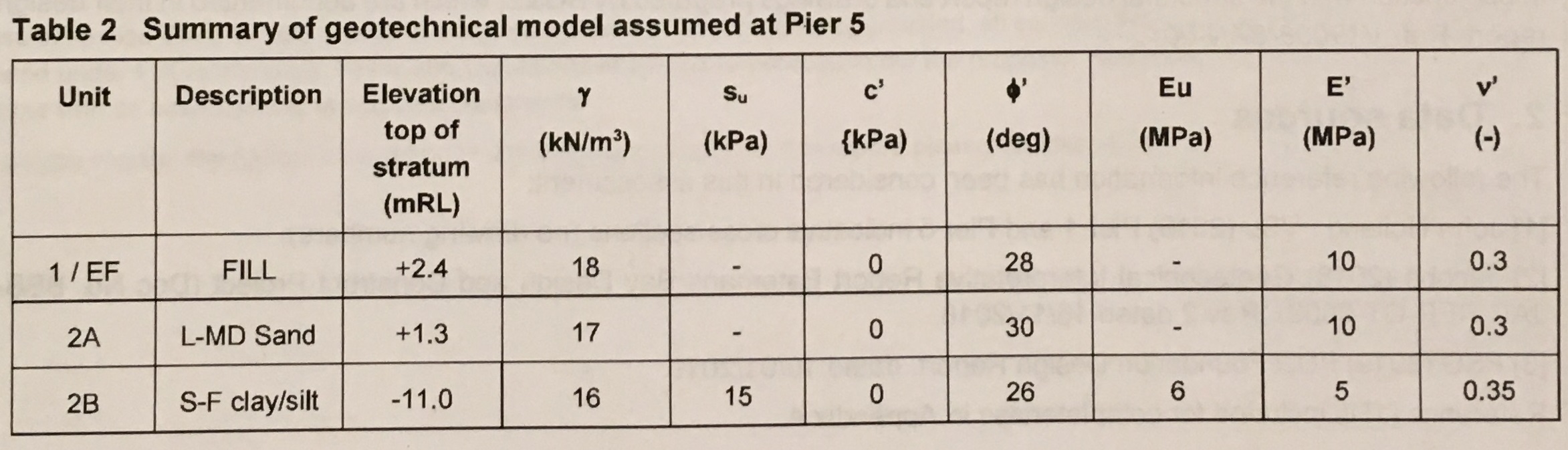
Ground investigation boreholes indicated a varying rock profile with bedrock occurring at approximately RL -5.000m AHD at Pier 1 but in excess of RL -30.00m AHD at Pier 5. The geotechnical design models for the cofferdams at Pier 1 and 5 are shown in the tables below. It was anticipated that cut-off could be achieved at Pier 1 but not at Pier 5 due to the rock-head depth.
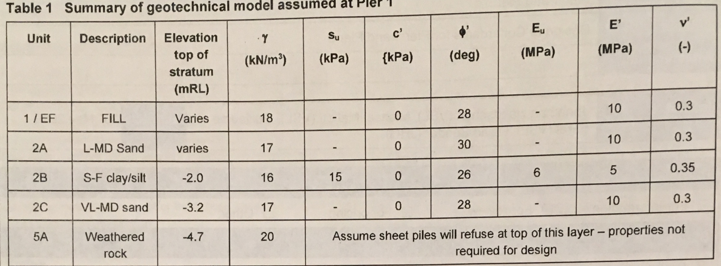
Pier 1 Cofferdam
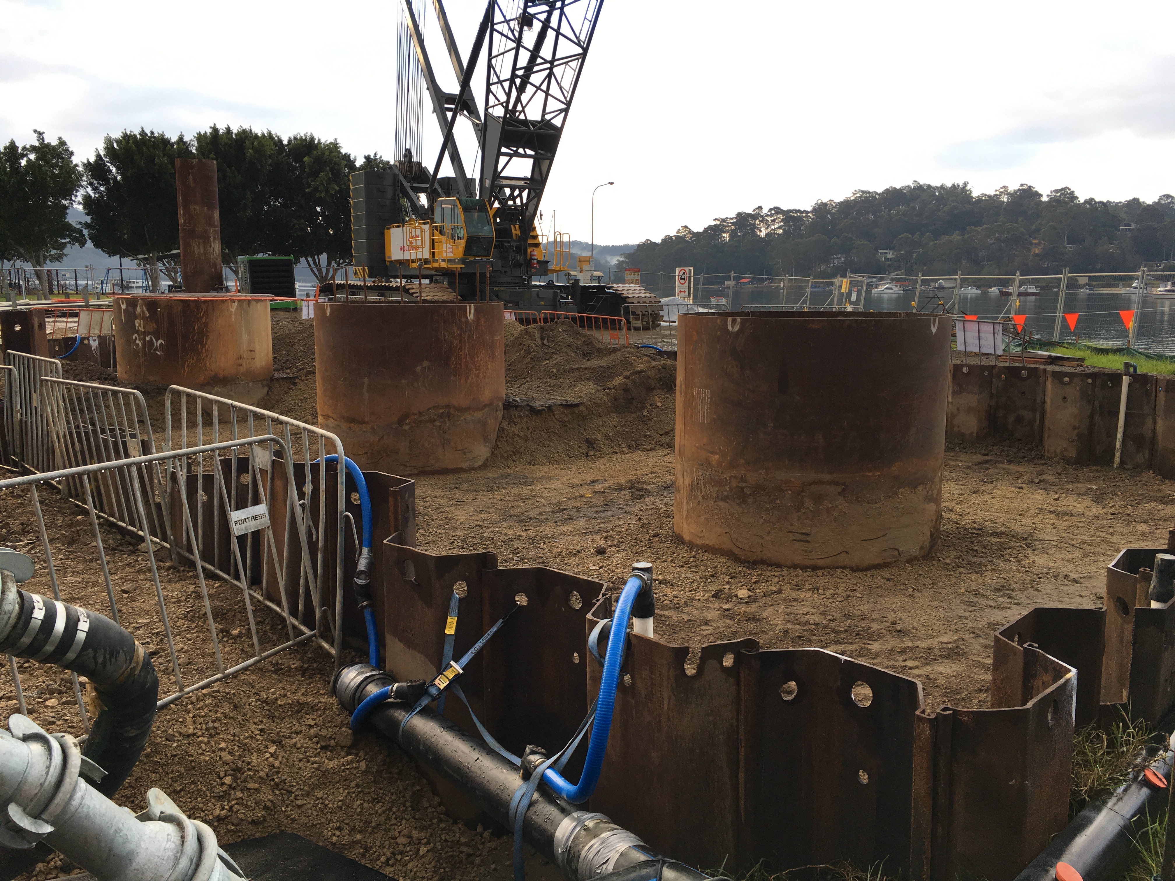
The northern cofferdam is located within the tidal zone. At low-tide, all sheet piles are above the waterline but at high-tide the majority of the cofferdam sheet piles are within the river.
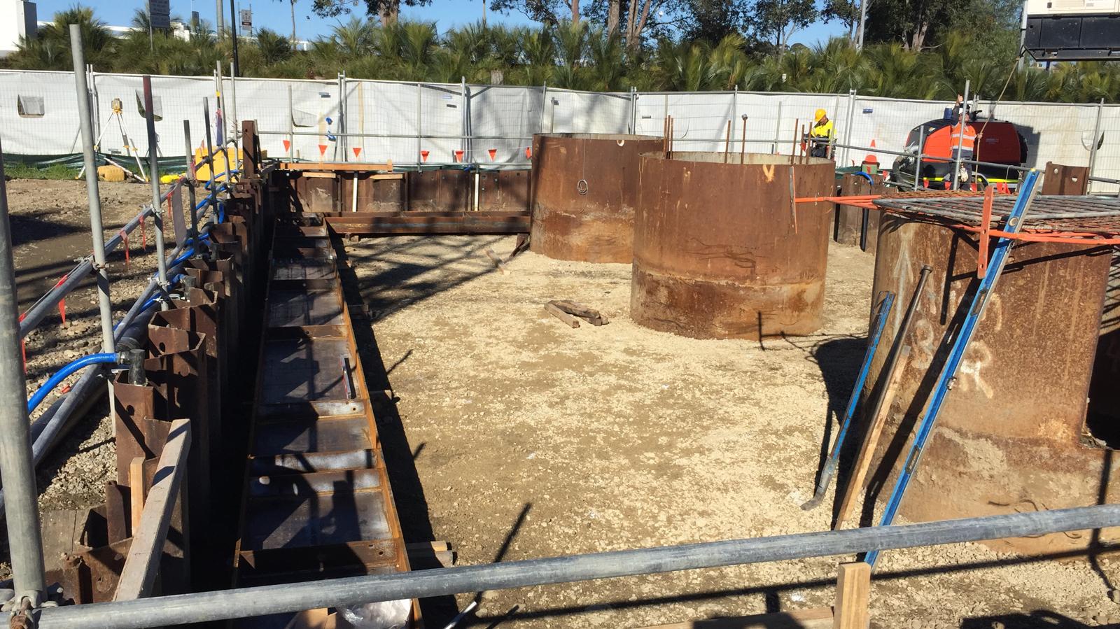
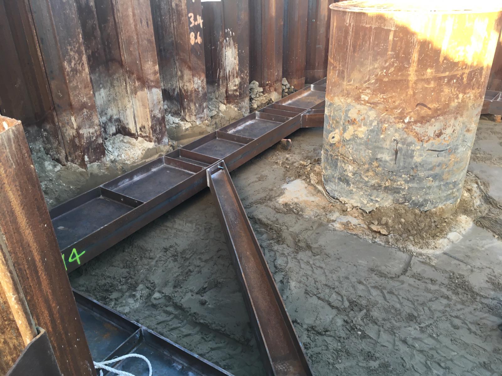
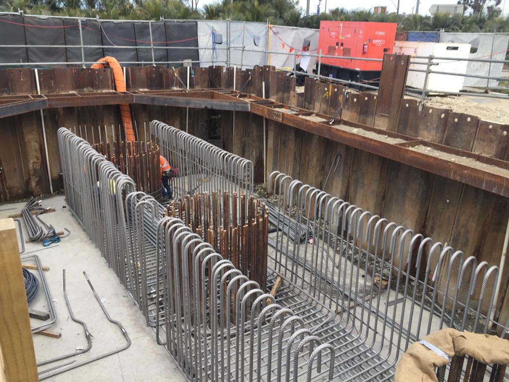
The cofferdam was constructed at Pier 1 in two stages. The first stage was to drive the sheet piles on 3 sides of the cofferdam to create cantilevered retaining walls for the construction of a TW platform for a piling rig. The rig installed 3 No. permanent bridge piles (1.8m diameter bored piles) before the cofferdam was closed. When the cofferdam was complete all sheet piles hammer-driven 200-400mm into the rock-head.
GU18N piles were procured and cut down on-site to reduce the number of piles required. The minimum design embedment was RL -5.000m AHD. The external ground level on the land-side was is RL +1.700m AHD with a final excavation depth of RL -1.200m AHD before 150mm of drainage rock and a 50mm blinding layer was placed.
Delta-13 corner connectors were used to increase water-tightness however the connector at the final corner could not be installed correctly due to differences between the design and as-built alignments.
Pier 5 Cofferdam
Due to program sequencing and existing access for the piling rig, the 3 No. permanent bridge piles were installed prior to the cofferdam construction.
The Pier 5 cofferdam is located approximately 15m from the edge of the river bank. 12.0m SPU-IIIw piles were driven under vibration to a minimum toe embedment of RL -9.600m AHD. The surrounding ground level is a TW platform at RL +2.000m AHD and a final excavation depth of RL -1.850m AHD was achieved (based on the on-site Geotechnical Engineer’s direction) before 300mm of drainage rock and a 50mm blinding layer was placed.
Again delta-13 corner connectors were used to increase water-tightness however the final connector could not be installed variation from the design and as-built alignments.
Problems:
- Budget. The cost of the cofferdams was overlooked during the tender, therefore, the cofferdam works had no budget. All decisions have been made on this basis with no appetite for additional expenditure to mitigate potential risks that may not materialise. Observation: Remember to include the cost of TW in tender submissions.
- Confined space requirements. When is a cofferdam a confined space? It seems everyone has an opinion and no two are the same! On the southern foreshore there are mangrove swamps which creates the potential for the soil to contain pockets of hydrogen sulfide gas (H2S) due to the decomposition of the organic material. High concentrations of H2S gas have been found at other project sites on the south of the river. A lot of my time planning the execution of the cofferdams was spent managing the potential confined space risks that could occur in the cofferdam due to H2S gas and plant or welding fumes. The risks to workers were reduced by providing ventilation fans to circulate air and using gas detectors to monitor the atmospheric (oxygen, carbon dioxide, hydrogen sulfide and explosive gas levels) to ensure levels remain within acceptable limits. As part of this process every shift I conduct a confined space assessment to determine if the cofferdams should be classified as a confined space. Observation: The risk of contaminated ground was covered in the teaching prior to Ex COFFERDAM but I don’t recall discussing confined space risks. Would this risk be worth highlighting to future PET courses?
- Lack of knowledge. There is a lack of knowledge about cofferdams amongst the site engineers. I found that I had more knowledge than most based on Ex COFFERDAM. One Senior Project Engineer initially designed the cofferdam (before an external geotechnical consultant was employed to verify the design). He has admitted that it was the first time he had designed one and would do things differently if he was to design another cofferdam. A John Holland supervisor has constructed cofferdams previously on other projects. Observation: You might actually know more than you think after Phase 1.
- Personalities. I have found the personalities of the site supervisors key in the standard of works they achieve. One supervisor is optimistic, under-resourced and over promises – consequently, he routinely fails to deliver. Another supervisor is well-organised and has invested time in building his team – they routinely deliver works to a high standard. Observation: It has been interesting to observe the same design delivered by the different teams and observe how their work ethos has affected the problems faced on site.
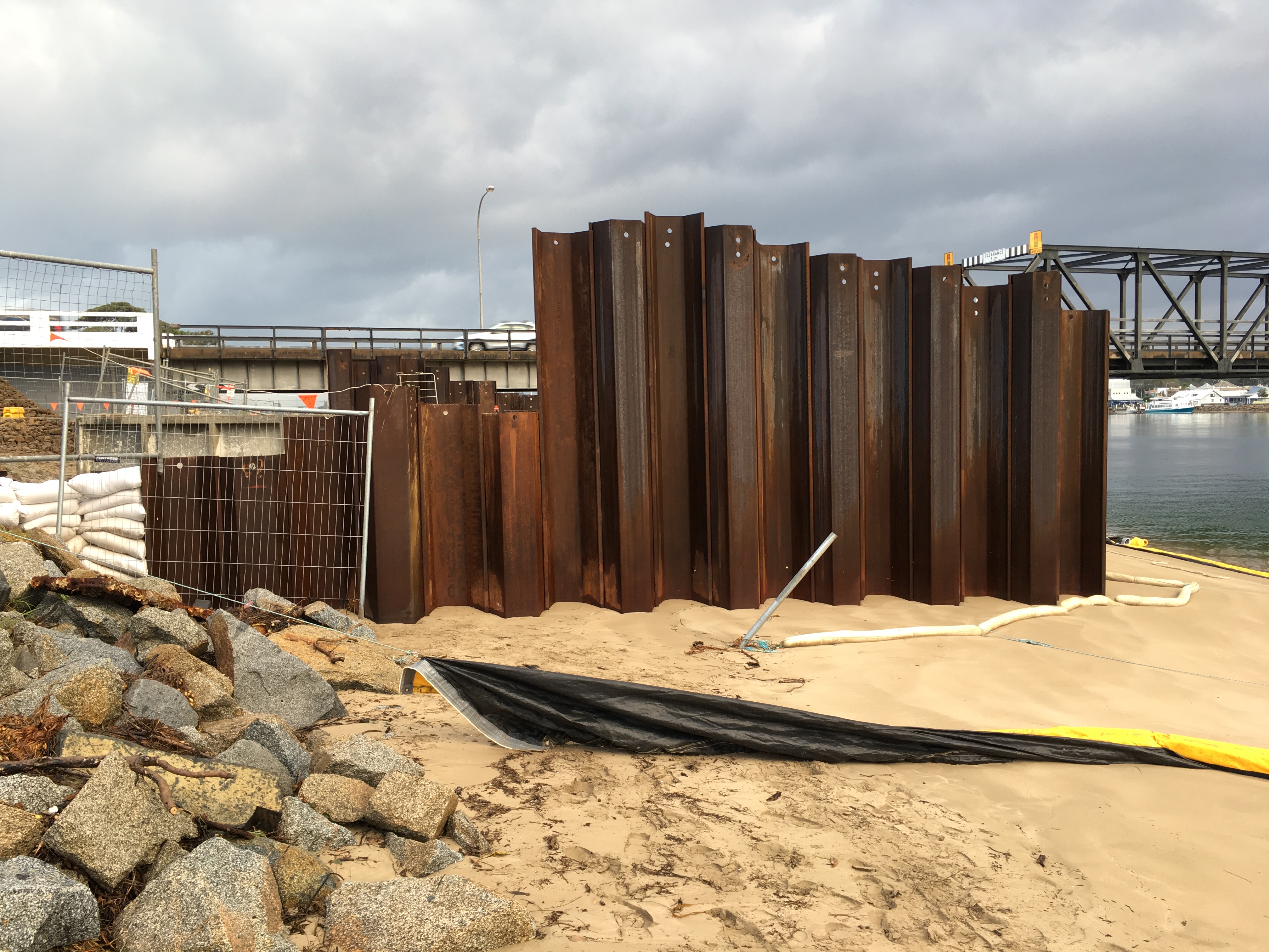
- Pile procurement. To reduce the cofferdam costs surplus/second-hand sheet piles and connectors were purchased from other construction sites. Essentially you get what you pay for – the poor quality second hand piles have caused a number of issues on site (increased labour costs, slower installation rates and clutch leaks). Observation: Trying to save money upfront has cost significantly more in the long run.
- Clutch Leaks. To save money, no clutch sealant was used prior to driving the sheet piles. The view from the optimistic supervisor was that the cofferdams would be fairly watertight and any leaks could be sealed post-excavation via calking rope or welding. At Pier 5 the wall leaks have been relatively minor except for at the corner where the delta-13 connector could not be installed. This resulted in a surface sinkhole as the groundwater caused fines to migrate into the cofferdam. This was sealed by blocking the gap and using stabilised sand to prevent further fines migration. At Pier 1, every clutch leaks…badly. Due to other work priorities, and needing to work at low tide slow progress is being made on welding the clutches. Observation: This is a big issue for permanent work construction as the groundwater will contaminate the rebar and prevent concreting works. Options for sealing a cofferdam after sheet pile installation are very limited – it is advisable to use clutch sealant before driving the piles as the other methods as it is too late when you start excavating.
- Boiling/Piping? At Pier 1 due to the rock-head and reduced toe embedment, there appear to be issues with a high hydraulic gradient boiling at the base of the excavation in the middle of the river sidewall even at low tide. I’m not sure if this would be classified as boiling/piping but you can see for yourself in the video below. This increases the groundwater flow into the cofferdam with 100mm routinely made overnight and up to 500mm over a weekend. In contrast, the increased embedment depth at Pier 5 appears to have minimised the issues with groundwater penetration due to the increased hydraulic flow path around the sheet pile and the increased soil plug weight inside the cofferdam. Of note, the drawings state ‘water tightness of temporary structure not designed. If waterproofing is required, to be designed and documented by others.’ Observation: I have not found any assessment of the hydraulic gradient or flow net for the cofferdam. This appears to have been largely ignored during the design stage. I have measured the recharge rate of the Pier 1 cofferdam but have been unable to assess this further due to other workloads.
- Groundwater. The lack of geotechnical knowledge and understanding of groundwater is worrying. A spear dewatering system was installed at Pier 5 but there was significant disagreement of when it should be turned on and off. The system was removed following the blinding layer installation as the system was extracting 0.5l/sec which the SPE felt could be managed via sumps. This is achievable during working hours however site environmental restrictions prevent dewatering out of hours which has resulted in a flooded cofferdam in the mornings and at weekends following high tides. The ability of the spear system to depress the groundwater level below that of the sump is not understood nor is the importance of running the dewatering system over a protracted timeframe to depress the groundwater levels. Interestingly I have just been instructed to organise the installation of a spear dewatering system in the Pier 1 cofferdam to reduce the water entering the cofferdam. I believe this is the only option we have to control water ingress below the blinding layer as the clutches are not sealed. Observation: The rush to demobilise ‘unnecessary’ dewatering equipment is causing challenges with the permanent works (reinforcement and concreting works) which need to be kept out of the groundwater.
- Alignment. There were significant issues with maintaining the design alignment when driving the sheets as no driving frame was used (sheets were driven individually). As fixed walers were fabricated the 300mm+ variation was significantly more than could be accounted for with metal packing shims. A Temporary Works Modification Request was approved which replaced the fixed waler support brackets and metal shims with restraint chains and hardwood packing. At pier 1 the location of HV cables within 300mm of the wall required non-destructive testing to expose the cables so the asset owner could observe the cables as the sheets were driven. This required formal notifications, additional Safe Working Method Statements and made installing and aligning the wall more challenging due to the open trench. Observation: Adjustable proprietary strut/prop systems can be adjusted more easily to compensate for installation inaccuracy. If using fabricated (fixed) props I recommend assembling the walers first in situ and using them as a driving frame to minimise alignment variations. Proprietary waler restraint chains were far easier to install than the fixed bracket design.
- Quality Issues. The works were due to be self-performed by John Holland (JH) employed labour to reduce costs. A JH crew started the sheet pile installation at both cofferdams but later handed it over to a sub-contractor (the Temporary Boat Ramp failure [see previous blog] disrupted the permanent piling contractor’s works so they were employed on day rates to perform additional works to minimise demobilisation costs). The cofferdams have subsequently been handed between JH crews. With the works starting behind programme the focus has been on time at the expense of quality. Pier 1 sits on the project critical path. The blinding pour was rushed and started too late in the afternoon to be completed within the site working hours. This resulting in inconsistent blinding levels above the RL and critical trench reinforcement (to support the pier formwork) being installed in the wrong position (horizontally and vertically). Critical sections of the blinding including the trench reinforcement have been ripped out and replaced loosing over 4 days of productivity at Pier 1. Observations: The lack of crew ownership combined with a desire to recover the programme and a vague ITP has resulted in the delivery of low quality work. This is most noticeable at Pier 1. The Pier 1 blinding pour should have been delayed. The engineer managing the blinding pour was pressured into making mistakes.
- Wall Monitoring. Part of the designer’s requirement was to monitor wall movement at 16 locations around the cofferdam (2 positions on each wall at waler height and 2 positions on each wall 0.5m above the base excavation level). Set deflection limits were agreed including 80% trigger levels to increase monitoring requirements. This was a great idea in principle but was practically impossible to achieve on-site due to physical site and line of sight constraints. This was discussed with the designer and a practical proposal developed on site. The wall monitoring was to be conducted daily until the wall movements stabilised. The monitoring identified that the Pier 1 land-side wall one wall moved 17mm (greater than the 80% threshold limit) over a weekend. This triggered significant consultation with the geotechnical engineers and structural designers to determine a solution. The wall movement was attributed to a surcharge load from an excavator (which was permitted in the design). As the deflection remained less than those permitted in the cantilevered state new deflection thresholds were agreed with the designers. The wall movements have no re-stabilised and are monitored bi-weekly by the site surveyor. Observation: The set wall monitoring procedure developed with the site surveyor was essential to detect the wall movement. Simple solutions developed in an office may not be practical on-site. The designers were receptive to adjusting the monitoring plan based on-site practicalities.
Any guidance or ideas of how to seal the cofferdam clutch leaks would be very welcome!

The state some of the second-hand piles arrived in…
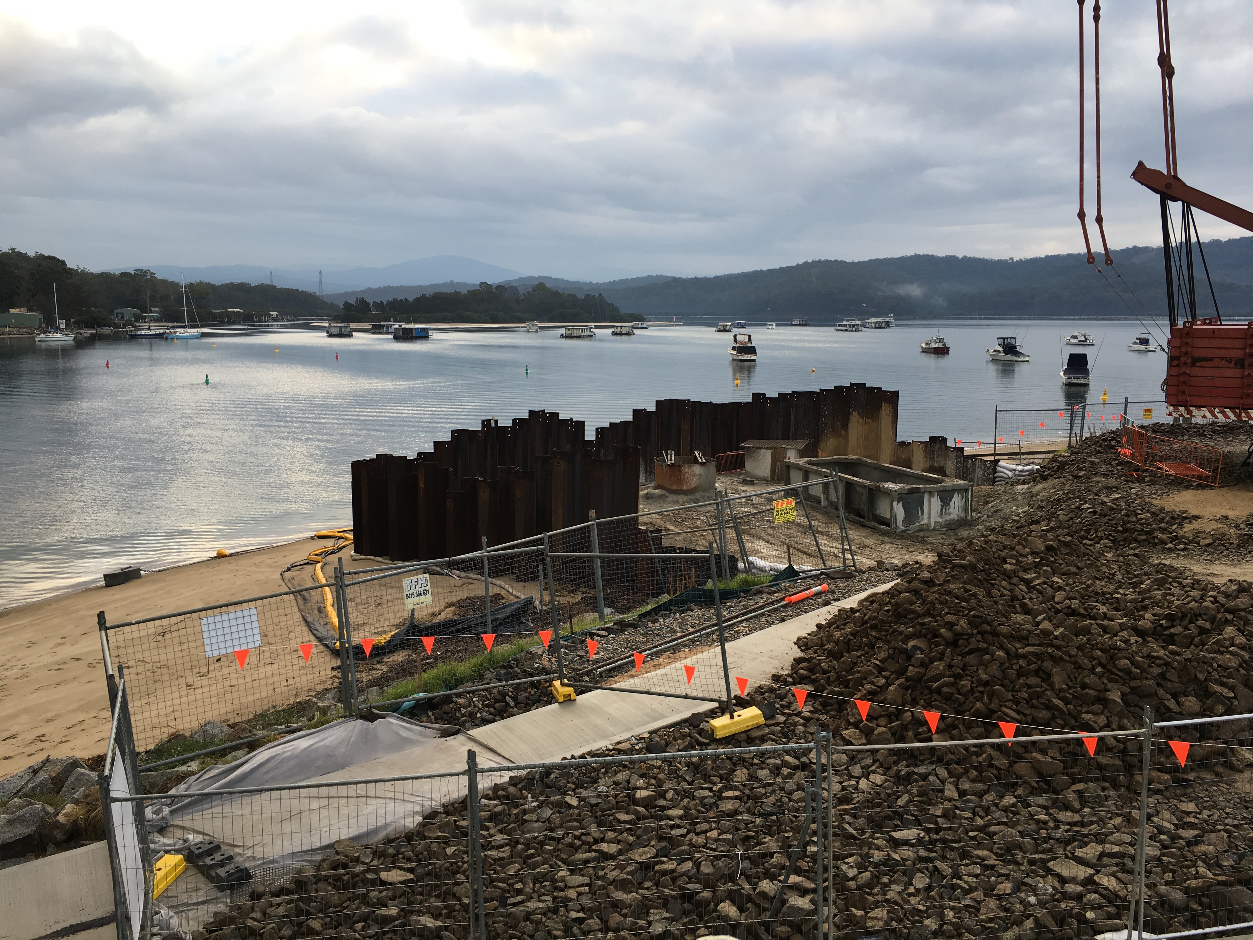
Pier 1 cofferdam as cantilevered retaining walls for the piling platform
Pier 1 cofferdam showing proximity to river at low tide. Piles on LHS are shorter to reduce the number of piles and prevent tides from entering cofferdam around the side during construction.
Pier 5 cofferdam at stage 1 dig (prior to waler install). The foreground shows the dewatering spear system and header main.
Pier 5 cofferdam waler installation.
Pier 1 delta-13 connector not closing on sheet pile clutch due to misalignment
The lack of delta-13 connector at the Pier 5 resulted in visible groundwater flow

The groundwater flow washed fines through the gap resulting in a sinkhole outside of the cofferdam.
Installation of walers at Pier 1 cofferdam (level appears lower due to removed piling rig platform removal and reduced toe depth.
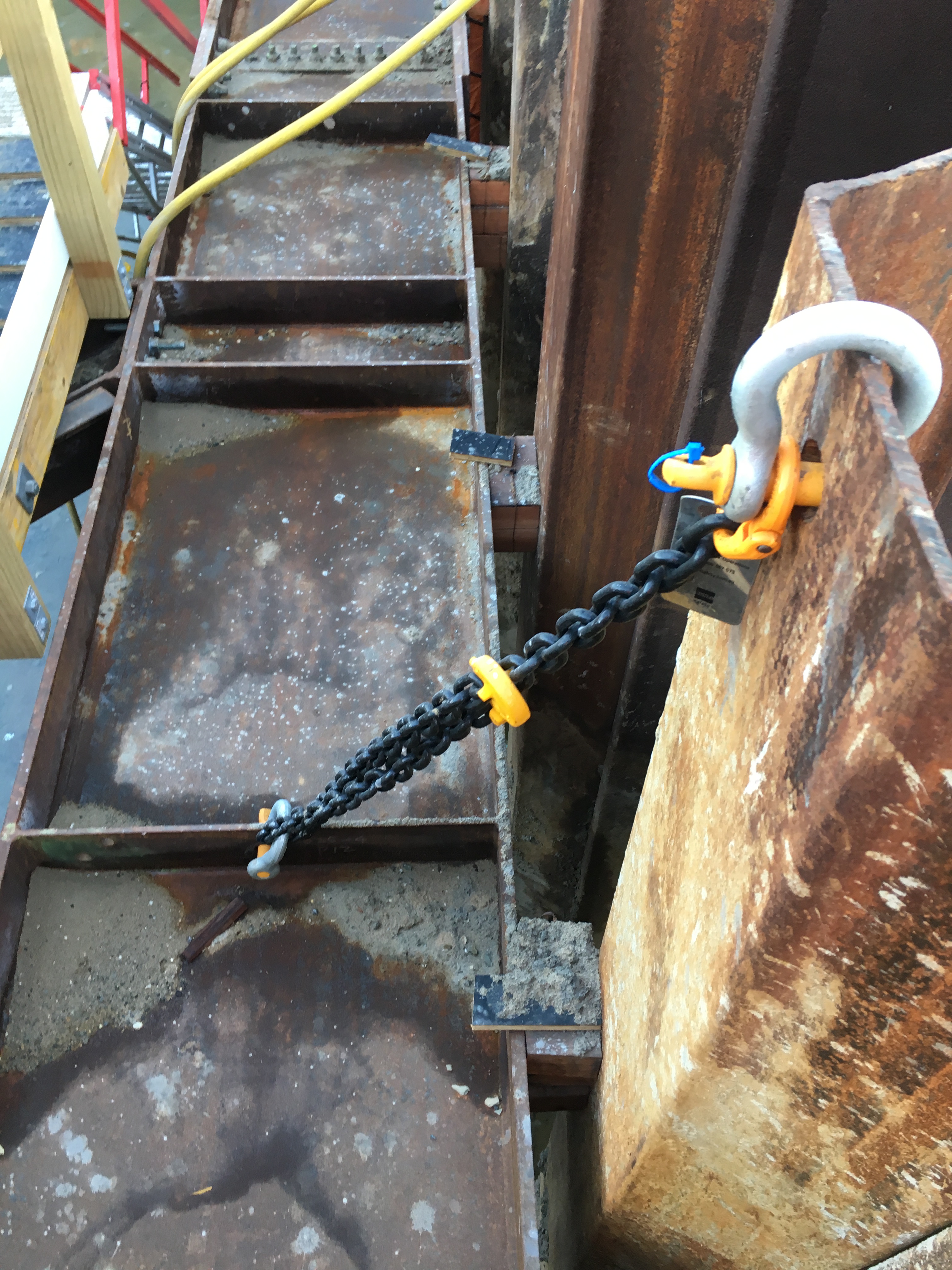
The waler restraint chains were used to solve the issue of a lack of sheet pile above the waler at Pier 5. The chains were easier to install than the fixed brackets. Note the timber packing that was initially due to be 1-10mm steel plate.
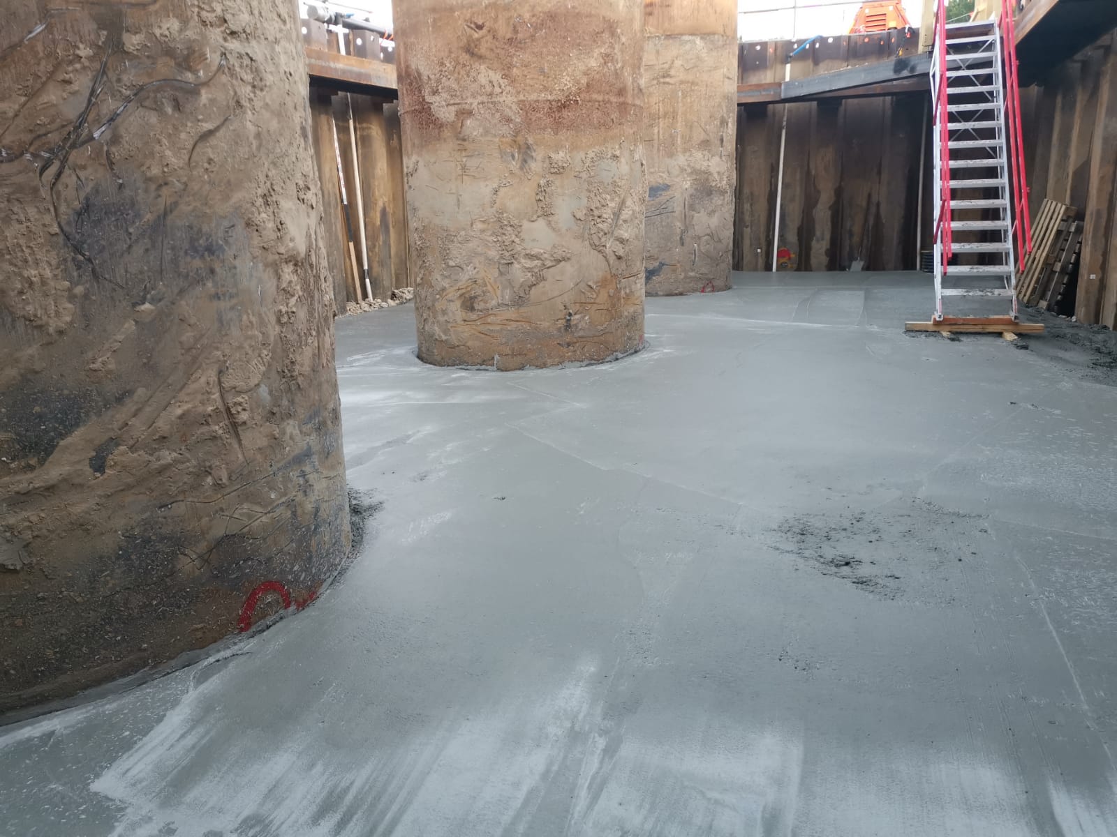
Blinding layer complete at Pier 5
Meanwhile high hydraulic gradient at Pier 1. Possible piping/boiling? The sand is being forced into the cofferdam from the river bank/beach outside the cofferdam.
Pier 1 water penetration through the clutches due to tide.
Flooding at Pier 5 due to groundwater. Usually <50mm.
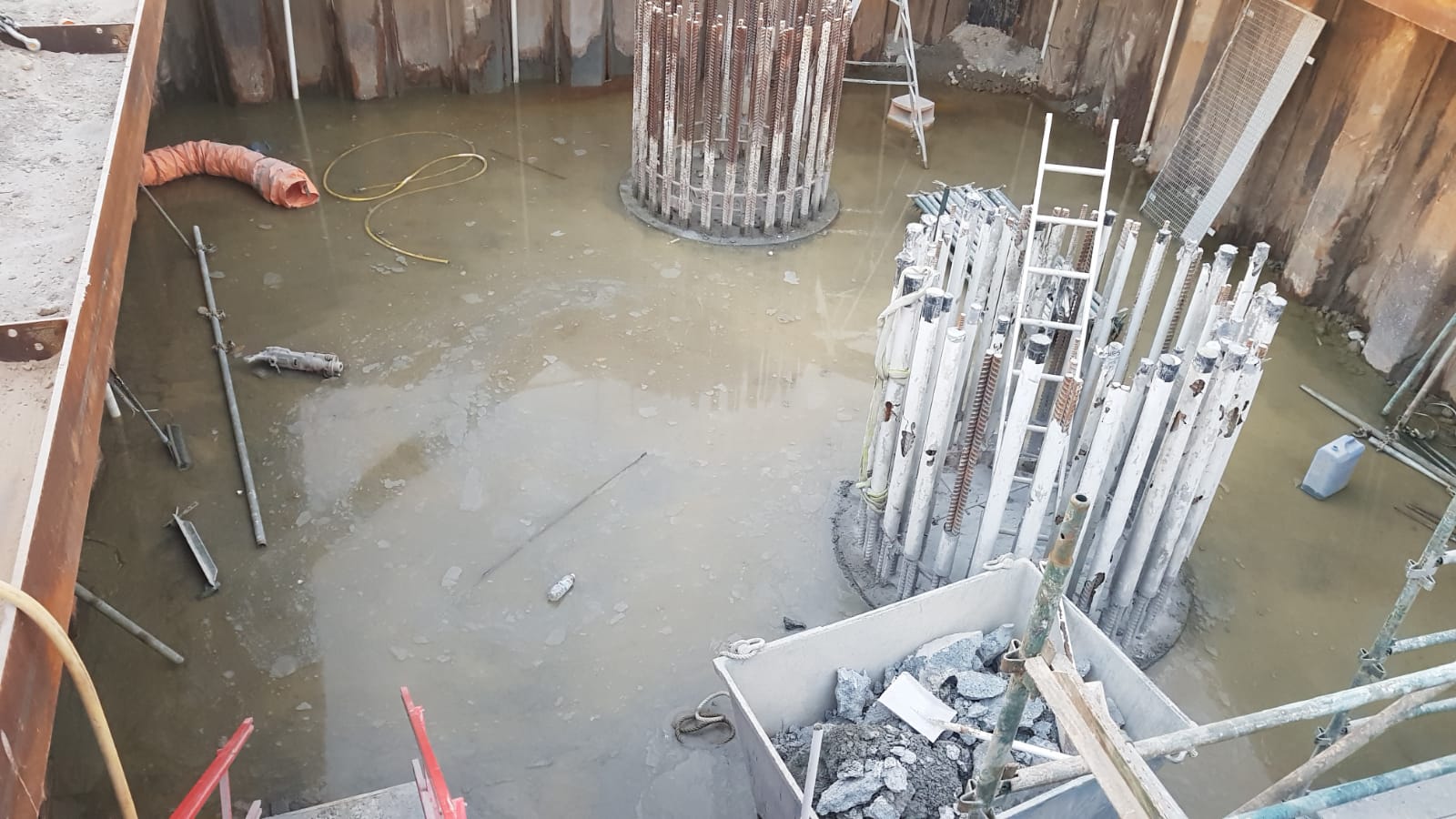
Flooding at Pier 1 cofferdam. My usual morning view of 80 – 100mm above blinding layer.
Pier 1 following a high tide
Pier 1 record water level of 500mm above blinding following a weekend with high tides.

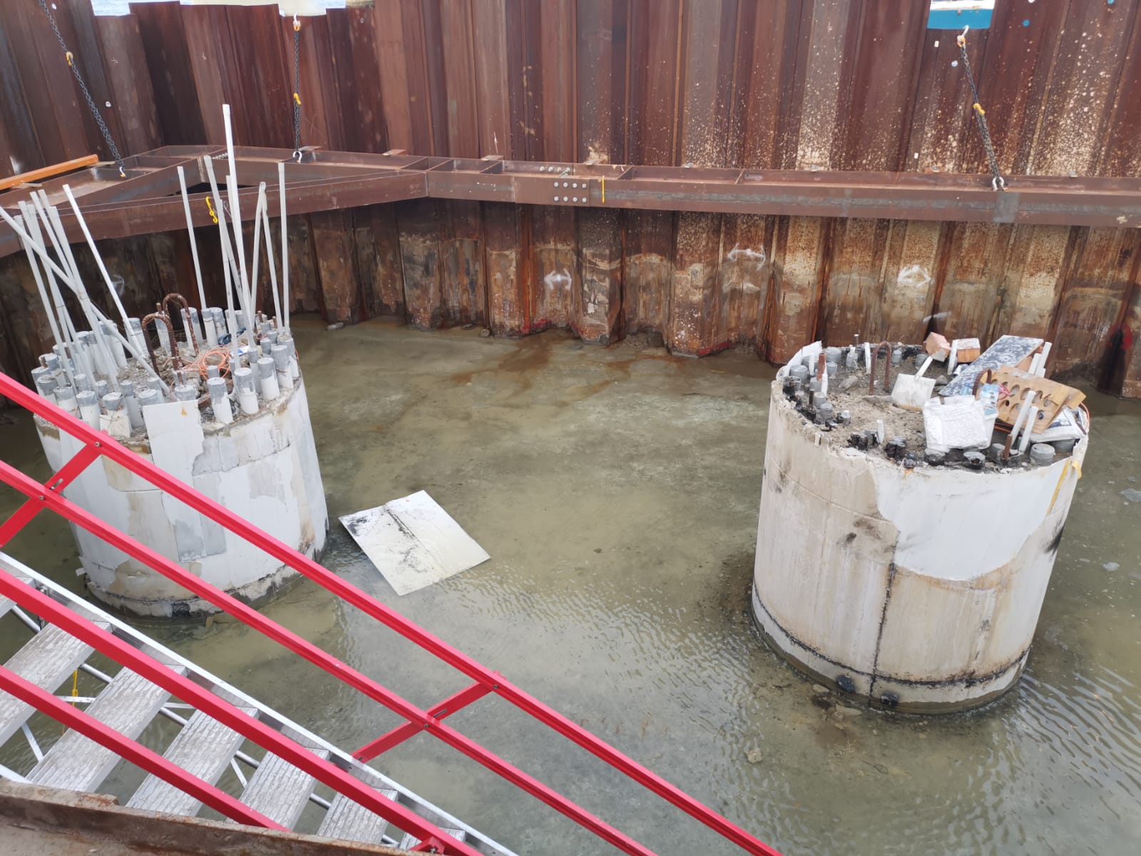
Pier 5 pile overpour break back complete. Cleaning rebar for insitu pile cap. Groundwater managed by sump pump (back right corner).
Current works at Pier 5. In situ steel fixing.

Current works at Pier 1. Breaking out blinding and reinforcement.

New blinding in the excavated trench was laid at Pier 1 today.
