Archive
The HAJ waste water treatment facility at HPC.
This will not be as long as any of Mark’s blogs
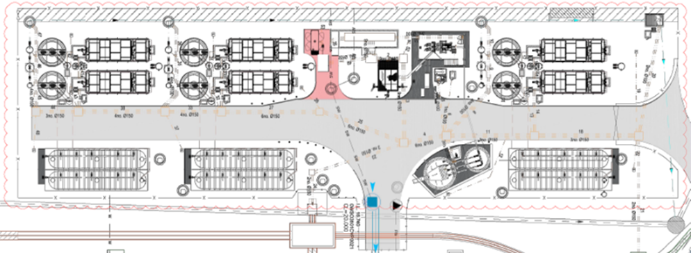
A large part of my time at HPC has been as the construction delivery manager for the temporary waste water facility, known as the HAJ. Designed to accommodate a peak flow of foul water of 33.8L/s for a peak of 9,775 construction workers. It achieves this through the 3 modules each consisting of a Primary Settlement Tank, Rotating Biological Contactor, Final Settlement Tank and a UV filter. Effluent from all 3 modules will flow into a final effluent pump chamber that pumps to a main header tank discharging through a pipeline of the end of the jetty. KBJV are the Tier 1 contracted to complete the Civil and M&E works, they have sub-contracted the main M&E installation to TES, a contractor from Northern Ireland who have in turn contracted much of the electrical work to Mike McDonald electrical services. Much of the plant is of the packaged variety supplied by KEE wastewater treatment technologies.
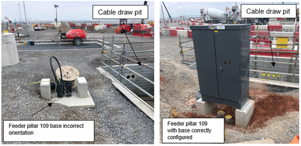
I arrived on-site after the main civil works were complete just in time for the M&E install, when I encountered my first issue (the first of many); feeder pillar 109.
Firstly, the loading profile for the facility was stated as 600kVA requiring 2 x 300mm^2 cables to provide the supply. I noticed this was very large and queried the value with SET, through investigation it was found that this was a typo with only a 60kVA load required. I proposed that one 300mm^2 cable would suffice to meet the demand and allow capacity for any future expansion. The orientation of the pillar was also incorrect as can be seen from the images below and KBJV also used a 90 degree bend which was too tight a radius to allow the cable to be drawn through! TES, the Tier 2 contractor tried to play a contractual game stating that the change in cable size would result in a change in the specification for a number of electrical components within the facility. They did this to try and buy some time as they were (and still are) behind schedule. This was solved buy instructing them to increase the outgoing cable from 95mm^2 to 120mm^&2.
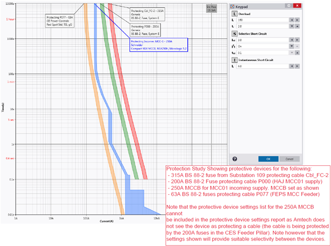
Having changed cable sizes I requested a grading study to be completed, TES and KBJV initially did not see the point, proving the the change in cable size would not cause any issues regarding the protection scheme, seen below. The end result is that all issues were resolved, but I learnt that competent contractors are not really competent and that you have to double check everything.
.
Temp PT
Tom, I’ll keep this one short just for you!
I’m currently writing a SWMS for the installation of 98t precast pile cap shells onto the marine piles. The idea is a RC precast shell is constructed on the foreshore and the steel working platform installed prior to the lift. Once in position, the gaps between the piles and the shell are grouted with underwater grout and the water removed to create a working area to remove the pile overpours and complete the RC pile cap. The working platform is then used to support the TW access platforms for the pier construction.
It seems quite a clever and well thought through. There are only a few challenges to the plan:
- Piling and pre-cast shell tolerances require a larger hole in the precast pile cap shell than the pile casing. This will let water in.
- In order to seal the gap between the pile casing and precast shell a seal is required to prevent environmental contamination of the river a seal is required. This will need to be positioned and removed (ideally without using divers due to cost). You can buy inflatable ring seals for this purpose but in true Blue Peter style we are making our own from plywood forms and rubber extrusion seals (think large car door seals). We have been doing lots of discussing and sketching of ideas in the office so I look forward to seeing if it will actually work.
- A method to lifting the precast shell and suspend it in the correct position is until permanently connected to the piles is required. This is what I want to blog about.
To lift the precast pile cap shell two lifting beams have been fabricated (each beam is made from twin 457 x 152 UBs joined together with additional stiffeners, bearing plates and lifting lugs). To suspend the shell at the correct position three hanging beams (same design as lifting beams) are used and will fix to the pile casing (2100mm diameter steel CHS 6mm thick). To counter the uplift forces a hold-down bracket and clamp system is proposed (but unworkable as we can’t source the required clamps) and are requesting a design change.
The shell lift will need to be conducted in two stages. The first using a 400t land-based crawler crane (with maxer) to position the shell closer to the river bank. The second stage will use a barge-based 400t crawler crane (with maxer) to pick up the shell and position it onto the piles. The problem is how do you stop the concrete being subjected to tensile stress?
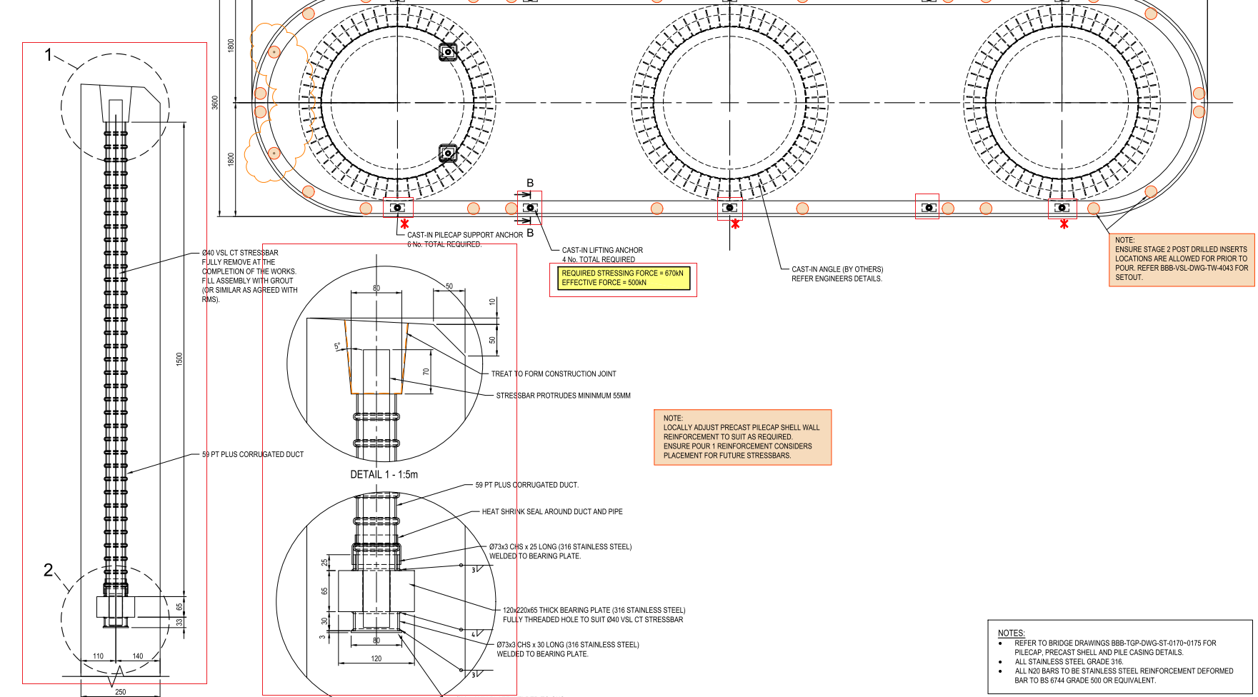
The solution is temporary prestressing. The design includes 10 No. 40mm diameter prestress bars anchored into the shell wall below the lifting/hanging beams. A number of load cases have been examined which determines the lifting case is the most critical. To prevent the development of tensile stresses the bars were initially due to be stressed to 670kN to give a retained stress of 500kN after prestress losses (mostly due to lock-off). Further calculations indicate the concrete shell would fail if the bars were stressed to 670kN so the pencil has been sharpened and a new prestress limit of 470kN is proposed (300kN retained stress). This is still undergoing verification but as the pile cap shell base was poured last week and the walls are being poured tomorrow things could quickly change.
I thought this was an interesting use of temp PT by VSL who specialise in PT (as Freyssinet’s main competitor) so I hope you enjoyed the read. Below is the proposed construction sequence and precast pile cap shell drawings (temp PT highlighted in red boxes).
Planned construction sequence:
Stage 1 (not shown) – install sealing rings.
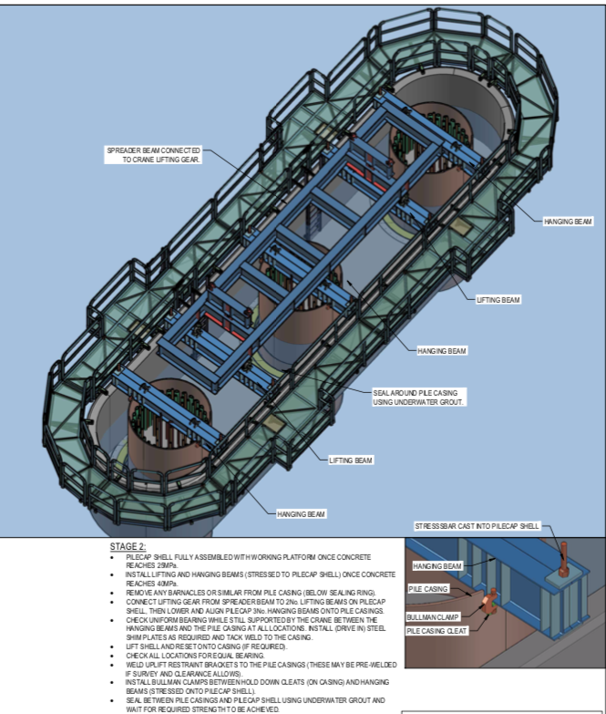
Stage 2 (above) – Lifting pile cap shell onto piles. Model shows lifting beams, hanging beams and temporary working platform.
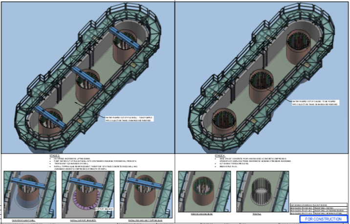
Stage 3 (above LHS) – Removal of lifting beams and sealing of gaps and removal of water.
Stage 4 (above RHS) – Second stage slab pour, removal of hanging beams and removal of pile overpour and excess casing.
Stage 5 (not shown) – Complete pile cap RC pour
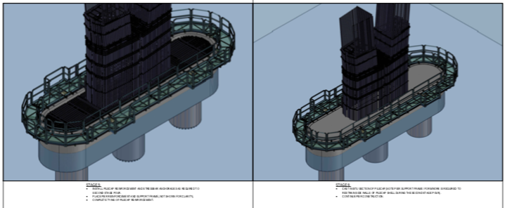
Stage 6 and 7 – Construction of bridge piers (additional working platform construction not shown).
Pile Cap Shell Drawings
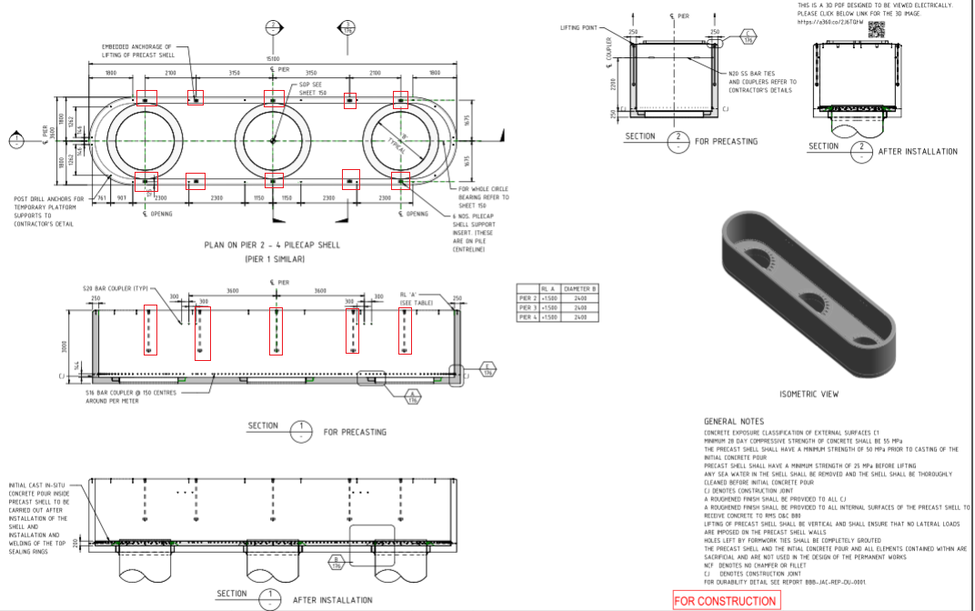
Pile cap shell drawing (above)
Temp PT drawings (above)
Revit Model
Tony Guy Partners (the permanent bridge designer) have added QR codes to their drawings with web links which allow anyone to download the revit model for that drawing from Autodesk myhub. No Autodesk software licenses are required and it allows 3d mark-ups, exploded views and sections/cuts to be viewed. These have been a real lifesaver for the engineers working on the rebar schedules/ITPs.
If you want to view the model you can download it from this weblink: Pile Cap Shell Revit Model
