Temp PT
Tom, I’ll keep this one short just for you!
I’m currently writing a SWMS for the installation of 98t precast pile cap shells onto the marine piles. The idea is a RC precast shell is constructed on the foreshore and the steel working platform installed prior to the lift. Once in position, the gaps between the piles and the shell are grouted with underwater grout and the water removed to create a working area to remove the pile overpours and complete the RC pile cap. The working platform is then used to support the TW access platforms for the pier construction.
It seems quite a clever and well thought through. There are only a few challenges to the plan:
- Piling and pre-cast shell tolerances require a larger hole in the precast pile cap shell than the pile casing. This will let water in.
- In order to seal the gap between the pile casing and precast shell a seal is required to prevent environmental contamination of the river a seal is required. This will need to be positioned and removed (ideally without using divers due to cost). You can buy inflatable ring seals for this purpose but in true Blue Peter style we are making our own from plywood forms and rubber extrusion seals (think large car door seals). We have been doing lots of discussing and sketching of ideas in the office so I look forward to seeing if it will actually work.
- A method to lifting the precast shell and suspend it in the correct position is until permanently connected to the piles is required. This is what I want to blog about.
To lift the precast pile cap shell two lifting beams have been fabricated (each beam is made from twin 457 x 152 UBs joined together with additional stiffeners, bearing plates and lifting lugs). To suspend the shell at the correct position three hanging beams (same design as lifting beams) are used and will fix to the pile casing (2100mm diameter steel CHS 6mm thick). To counter the uplift forces a hold-down bracket and clamp system is proposed (but unworkable as we can’t source the required clamps) and are requesting a design change.
The shell lift will need to be conducted in two stages. The first using a 400t land-based crawler crane (with maxer) to position the shell closer to the river bank. The second stage will use a barge-based 400t crawler crane (with maxer) to pick up the shell and position it onto the piles. The problem is how do you stop the concrete being subjected to tensile stress?
The solution is temporary prestressing. The design includes 10 No. 40mm diameter prestress bars anchored into the shell wall below the lifting/hanging beams. A number of load cases have been examined which determines the lifting case is the most critical. To prevent the development of tensile stresses the bars were initially due to be stressed to 670kN to give a retained stress of 500kN after prestress losses (mostly due to lock-off). Further calculations indicate the concrete shell would fail if the bars were stressed to 670kN so the pencil has been sharpened and a new prestress limit of 470kN is proposed (300kN retained stress). This is still undergoing verification but as the pile cap shell base was poured last week and the walls are being poured tomorrow things could quickly change.
I thought this was an interesting use of temp PT by VSL who specialise in PT (as Freyssinet’s main competitor) so I hope you enjoyed the read. Below is the proposed construction sequence and precast pile cap shell drawings (temp PT highlighted in red boxes).
Planned construction sequence:
Stage 1 (not shown) – install sealing rings.
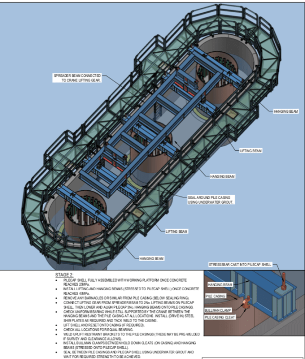
Stage 2 (above) – Lifting pile cap shell onto piles. Model shows lifting beams, hanging beams and temporary working platform.
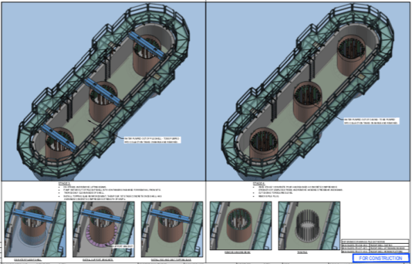
Stage 3 (above LHS) – Removal of lifting beams and sealing of gaps and removal of water.
Stage 4 (above RHS) – Second stage slab pour, removal of hanging beams and removal of pile overpour and excess casing.
Stage 5 (not shown) – Complete pile cap RC pour
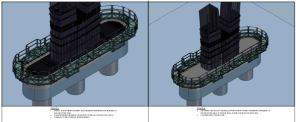
Stage 6 and 7 – Construction of bridge piers (additional working platform construction not shown).
Pile Cap Shell Drawings
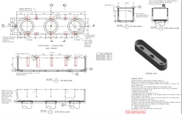
Pile cap shell drawing (above)
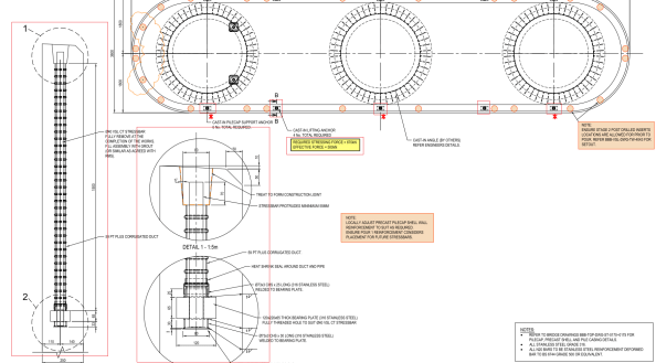
Temp PT drawings (above)
Revit Model
Tony Guy Partners (the permanent bridge designer) have added QR codes to their drawings with web links which allow anyone to download the revit model for that drawing from Autodesk myhub. No Autodesk software licenses are required and it allows 3d mark-ups, exploded views and sections/cuts to be viewed. These have been a real lifesaver for the engineers working on the rebar schedules/ITPs.
If you want to view the model you can download it from this weblink: Pile Cap Shell Revit Model

Mark, maybe I’ve missed something but why is the pile cap being installed below the water line? It seems to make everything else a bit more difficult.
I asked today in the office. The TGP (bridge designer site rep) doesn’t know. Possibly due to boat impact, aesthetics or an entirely different reason. Sorry I can’t give the real reason but he’s constructing about the water line would certainly have made the cap easier to install!
I’m always interested in the use of PT to avoid tensile issues. I’m not clear from this where the tension is arising or how it is being generated. It looks from the drawing as if the tendons are being placed vertically in the side walls of the casing which would suggest they are addressing shear or torsion, presumable a risk in the lifting operation that reduces as soon as they are fixed in place.