Where is the real critical path?
Being a steel framed building it won’t surprise anyone to hear that the erection of the steel frame is the current critical path activity on my site. On the face of it, all is going well; steel is flying into place and the fixing gangs are able to knock off at 2pm every Friday to head back up north for the weekend. There is no evidence of surplus steel on the site and almost everything is installed the day it arrives, leaving the lay down areas empty. All good, yes?
Unfortunately, no. While the installation can run like clockwork, the real critical path on this project is more than 200 miles away at the fabrication shops in Bury, Lancs. The volume, weight and complexity of the members being installed in the early phases of this job have the fabricators running to max capacity and, in essence, they are failing to provide steel to site quickly enough. This is resulting in considerable delays that are out of the hands of the sub-contractor’s site management teams. In an effort to understand the problems they are facing we headed north for a tour of the fab shop turning out the biggest bits for the job.
E&Ms can probably dip out of this one now with the fortune cookie take-away that the critical path isn’t always where you think it is and off-site manufacture is vital to the programme. Anyone else can carry on for a photo-heavy tour of the fab shops and what the pieces look like on site.
INTRODUCTION
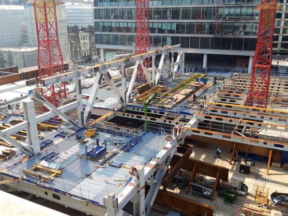
To set the scene for our visit to Bury: the early stages of this project build are 6 parallel ‘launch’ trusses which support the erection of an arch, together spanning between a pair of columns which are cast into large diameter pile heads. The trusses are two storeys tall (between level 1 and level 3) and the arches join at level 10. Each truss alone weighs around 1000 tons and is over 60m long. Pieces are manufactured then brought to site to be bolted together to form the truss.

Structural skeleton showing 6 arches through the building above the launch trusses.
When (almost) complete the launch trusses should look something like this:
Launch truss approaching completion with top chord fitted along the central section.
So how do we get to this point?


Steel arrives at the fabricator as either rolled sections or plate which are then cut to length and brought onto the shop floor for fabrication.
BASE PLATES

Work on the column bases starts with the base plate which has a shear key and reinforcing cage welded to the underside.

Plate sections are welded along their length into girder or box sections then welded to the top side of the base plate.

For simple runs semi-automated submerged arc welding can be used. This puts down more weld metal than hand-held options and is easier on the operator for numerous straight runs. Note the angles tacked onto each end of the run to allow the machine to over-run then turn around. These are ground off afterwards.

Girders are welded to the base plate before bracing and stiffeners are added. All pieces are then QA tested and dispatched to the paint shop.

A ‘standard’ column base installed with intumescent paint. The rebar on the underside laps with bars protruding from the pile cage, within the casing. The shear key is then concreted into place, pouring concrete through the mouse hole in the base plate seen in the pic.
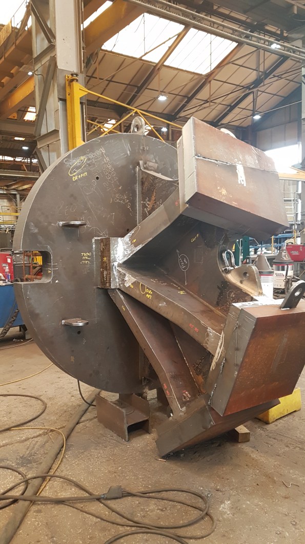
This is one of two special base plates which will support a tripod of box sections in one corner of the building. If the three column bases were ‘fingers’ the web between them is a single piece of plate steel, cut with the design curves and welded to the base plate. The column fingers are then added on either side and the caps applied. In this photo, from bottom to top, the ‘finger’ plates are 100, 150 and 180mm thick steel plate. The knuckle at the bottom is 240mm thick.
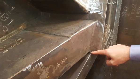
FPBW where a ‘finger’ meets the ‘knuckle’ in 150mm plate. Starting from inside the bevel (as pointed to in the pic) this weld required around 800 passes by the welder, by hand.
The complexity of some of the columns gives some explanation for the timelines required for their manufacture. This latter ‘special’ column has been in fabrication for 6 weeks and will spend at least another week being shot blasted and painted on it’s way to site. One of the columns was found during QA to have a lamination issue (layers of steel forming the plate pulling apart from each other) so had to be made again from scratch – rushed through production at best effort it has arrived on site today, 5 weeks behind its initial schedule.
COLUMNS
The columns, or column head nodes, which sit on these bases are fabricated box sections. In order to transfer load across the whole area of the capping plate, the surface needs to be exceptionally flat. The sections are fabricated and prepared then milled to achieve the desired tolerance for on-site welding to the column base plates.
Column section after fabrication, awaiting milling.

Milled column bearing end showing the bevelled edges to allow butt welding on site.
CHORDS
The launch trusses have their principal chords at level 1 and level 3. The lower is erected first, spanning on temporary works, and the upper chord is added afterwards with the tie members. The fabrication of these complex members is time consuming and mistakes in the fabrication could set the project back weeks.

To create the truss nodes girders are combined and web stiffeners added.

The preferred weld type is full penetration butt weld (FPBW) but the steel needs to be extensively prepared to allow this process. Incoming plate needs to be bevelled to allow the full penetration of the weld. The weld metal then returns run after run to fill the bevel and create the joint (finished example on the left side of this pic). The hole in the web (called a cope hole) allows for continuity of the weld through the web; without it the right-angled joint between web and flange becomes a stress concentrator.

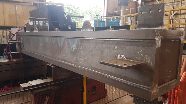
The finished article (almost) awaiting dispatch to the paint shop
ERECTION PROCESS
Once fitted to the pile, the standard truss columns will have bracing and a column head node either bolted or welded to them to support the lower chord of the truss.

Lateral and diagonal bracing on a column base plate

The column head node connecting, in this case, three adjacent piles. This was the first to be built to provide maximum stability to the frame while the lower launch truss chord was installed. This single lift was in excess of 20 tons, testing the limits of the tower cranes on site.

With the head node and back span (right) in place the lower truss chord was connected (left)
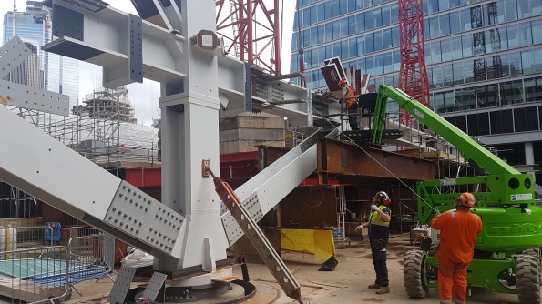
Making the splice connection for the first full span across the site.
Some weeks later the top chord is added with the tie members
SUMMARY
No amount of additional effort on site can speed up the construction process when the supply of finished members to site is insufficient. In this case the fabricators are working well and produce high quality products to site; unfortunately they are at max capacity and supply is still not meeting demand. With no float in the fabrication programme set backs hit hard and delays are felt to their fullest with the repercussions being felt on site.
For my part, I would advise anyone to get out and see their off-site processes (whatever they may be) whenever they can. Not only does it humanise the process, it is a vital part of construction that should be fully understood throughout the supply chain.

This is exactly the same as our precast concrete on site. There are two key issues:
1. They have a 10d lead time and due to the number of different types required for each row it is difficult for them to get a factory process going as the elements are quite varied between rows.
2. For us the piling is the critical path activity due to the overheads of keeping the barges running, ~60k/d standing costs, therefore they are full steam ahead. The precast production can’t keep up.
A nice blog
It has always been the case that one of the critical issues in steel frames construction ( by comparison with concrete) is lead time.
In your case the fabrications are highly complex. Moreover the number of repeats in the scheme is low and this would make the fabrication effort human rather than machine centred….hence an even longer lead time
-I was wondering which fabricator…is it and offshoot of Hares of Severs ?
One of the beauties of steel work is the transparency of the from and associated load paths or so I always thought. I am looking at this however and wondering if it has been analysed as a pin jointed truss or whether there is a subtle use of moment transfer through the joints. Have you done a Q&D load take down and analysis? The flange thicknesses on ‘tensile’ elements looks to be no different to the ‘compressive’ elements, which is odd, also the flare on the columns at their base implies moment transfer both to connected elements and to the head of the pile. All rather odd.
I absolutely agree with your stance on the need to understand the full supply process in anything your are constructing. This is an essential part of QM and extremely pertinent to everything you will do in military construction. It is, after all, a key risk and that is what we strive to manage!