Temporary works design – MEWPs
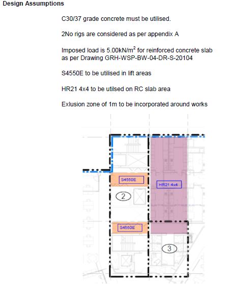
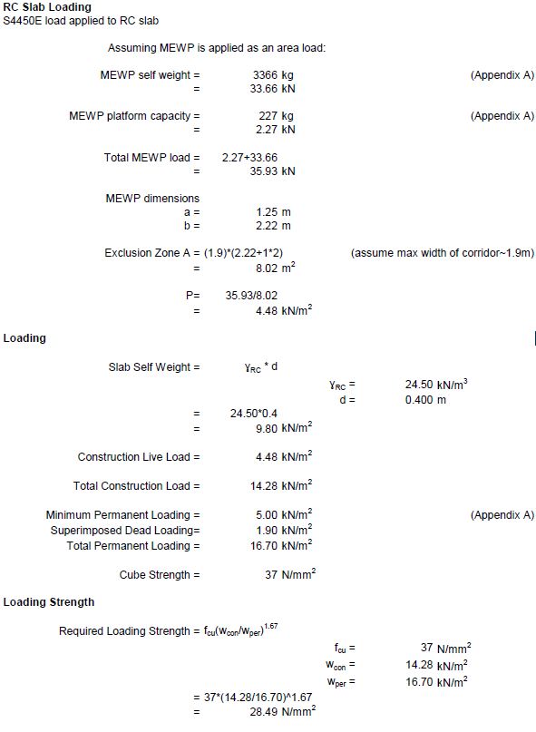
General. I have been reviewing the temporary works design that we have received on site for the use of some MEWPs on our suspended slabs. Two different MEWPs are to be used, one at approx 35.9 kN when loaded with a small footprint (1.25×2.22m) and a larger version, 69.3 kN when loaded with a footprint of 2.27×5.47m. The maximum slab span in the working area, is a two way spanning 9.48×6.4m with a qk of 5.95 kN/m2 and 6.9 kN/m2 in the smaller area shown below.
Temporary works designer (TWD) assumptions
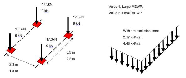
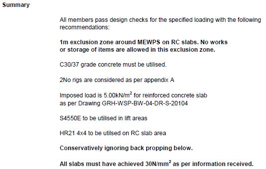
Method. I initially did some conservative calculations applying the combined load of two wheels at the mid span compared against the design UDL to check the TWDs value. The temporary works designer however has applied the MEWP as an area load with the addition of a 1m exclusion zone around each one. They then verify that this is less than the permanent loading before stating the loading strength required of the concrete. Note the loading strength is not a concern as the slabs have reached their permanent strength.

Limitation. An exclusion zone is normal around a MEWP however as work progresses equipment and furniture may already have been installed and so the surrounding area may not be completely clear. Also note the smaller MEWP must work in a corridor so a smaller exclusion zone has been included above.
TWD summary
Question. Is it appropriate to apply a vehicle load as a UDL in this way (this reminds me of the UDLs/tandem systems we used in bridge design)? Should alternative load models have also have been used to check this was the most onerous version?

I’d love to give a definitive answer to the question but the challenge with that is that…it depends! What is the geometry of the slab (spans, thickness, location of reinforcement and area of steel provided). Only then can you know the Effect of the proposed applied actions (design moments and shears). You can then check the resistance of the designed element. An alternative way of dealing with this, which appears to be applied in some of the above approach, is to ask if the proposed load is less than the design load. The only challenge with this is that it appears that the slab has not achieved its design capacity yet?