Temporary Works Tour: 1-5 Grosvenor Place
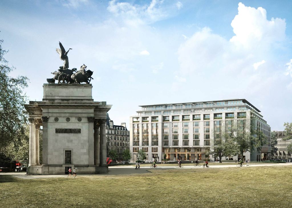
I recently visited a project in London where Sir Robert McAlpine Design Group are the temporary works lead. The project is to build a new hotel/apartment building near Hyde Park at 1-5 Grosvenor Place for Hong Kong and Shanghai Hotels. The building comprises 9 floors above ground and four to five basement levels below. As the basement construction period is significant due to the complex below ground structures, and the volume of material to be excavated and removed from the basement, the method of construction has been ‘top down’. This allows for the basement to be excavated and constructed concurrently with the superstructure construction and fit-out above, with savings to the programme. The building comprises four reinforced concrete ‘cores’ in each quadrant of the building which provide the main vertical access with a central courtyard in the centre. The central courtyard is currently used as the access for plant and material to the basement levels during construction, but will be covered by a garden on completion. The main structure has been completed with the first floors now being clad. The last two floors of the basement are currently being excavated down to approximately 20m below ground level.
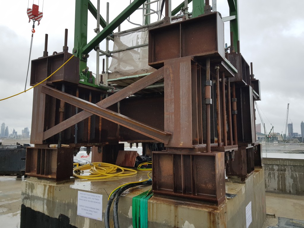
The temporary works on this project have been significant and I thought I would show the extent of them here. At each core of the building a crane has been placed on the roof. Placing cranes on the cores allows the building to be substantially completed and made watertight without having a void through the building for the tower crane mast. This has required a temporary works solution to provide a base to fix the crane. The supporting concrete core has been designed and enhanced to withstand the tensile stresses caused by the crane which has required bursting steel reinforcement. Note also the long post stressed threaded connections which are required to take the tensile stresses of the crane.
The site itself is very restrictive with very limited space for site offices. The solution has been to construct offices cantilevering out over the adjacent carriageway with a steel frame to support the offices above. To limit the loading on the pavement on which it is founded, a reinforced concrete raft has been cast over the pavement. Access positions have been required at any existing manhole or service cover locations. Further resistance to overturning has been provided by casting holding down bolts into existing grouted or concrete filled vaults below. The limited space has also required a solution for site traffic. This has been overcome by constructing a temporary steel structure to support a ramp and bridge through the courtyard of the building.
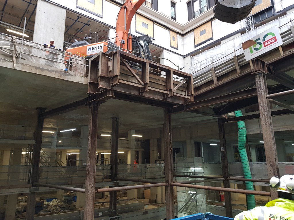
The steel structure is supported by large plunge columns that will eventually be removed and cut at pile cap level (see columns highlighted in green in the drawing below). The ramp and bridge allow site traffic to enter one side of the building and exit the other. A telescopic clamshell bucket shown in the image above is able to extract the spoil from the basement levels below and load it onto trucks passing over the temporary road structure.
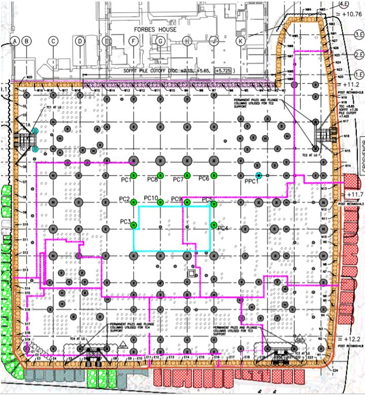
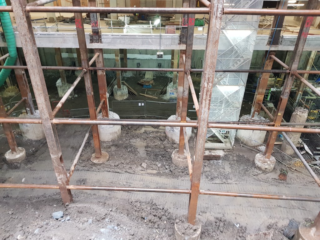
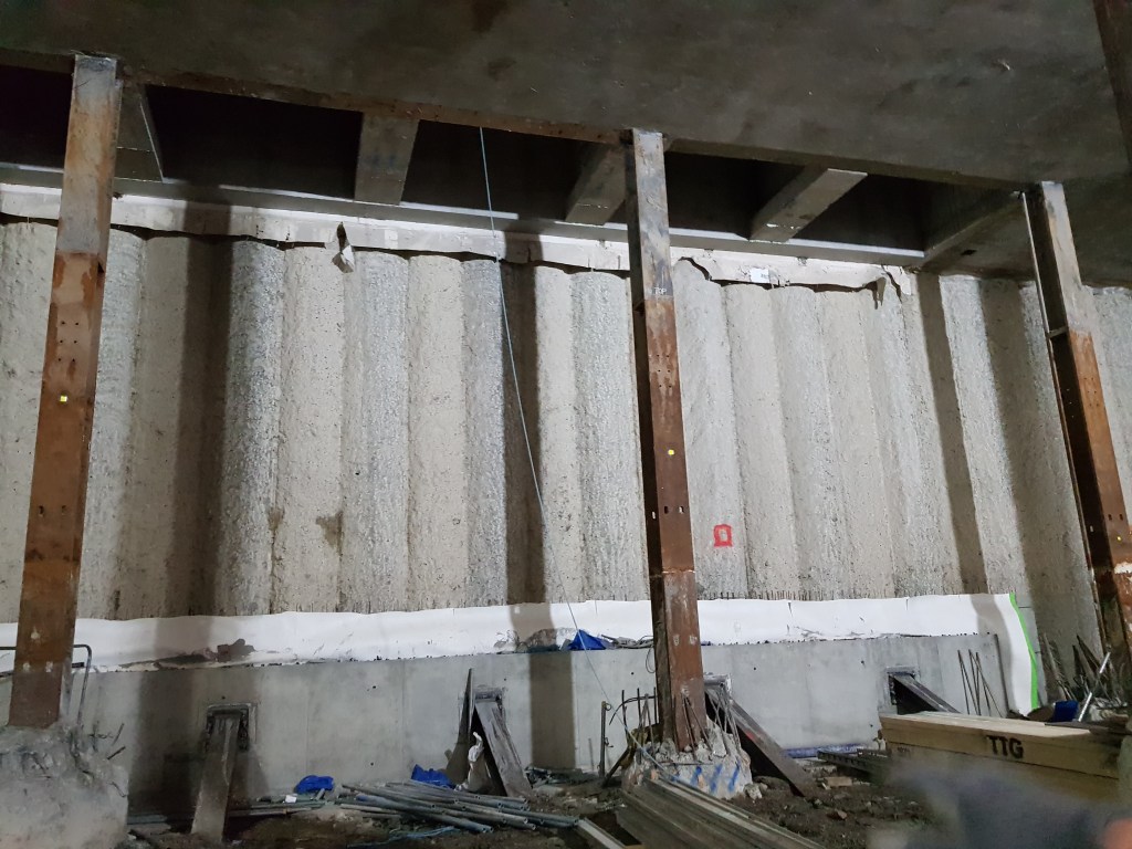
At basement level 1.2m diameter secant piles have been installed around the whole perimeter of the site (orange above). In particular propping has been required to strengthen the piling on the west end of the site where another building abuts the site closely (purple line above). This has been to limit the deflection of the secant piles and therefore limit the effects on the adjacent structure. Inclinometers have been installed down the length of these piles to monitor any significant deflection.
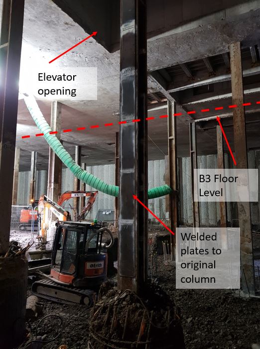
The basement is currently being excavated over the final two floors. This has been in order to enable large sized plant to operate and to allow removal of adequate volumes of clay per shift. Originally the design of the building only included three basement floors as planning permission for a fourth had not been granted during the design phase. However, later during construction a fourth basement floor was approved. This caused an issue with some of the existing columns that had already been installed. They would be too slender to take the loads from above in the temporary state before basement level 3 had been constructed. The increase in effective length between B2 and B4 level meant that some of the columns would need to be modified. In the image below shows where additional plates have been welded to the flanges of the columns to make them stockier and reduce their slenderness ratio.
The columns at higher level were originally to be encased in reinforced concrete. However, this has recently changed as the client now wants a masonry finish to the columns. This means that the cross sectional area of the columns are reduced, thus a reduction in the second moment of area. My involvement with this project so far has been to evaluate whether the columns are able to still take the axial loads without this reinforced concrete encasement.
This demonstrates the significant amount of temporary works involved in a project of this size, especially in a congested site like London. This offers some excellent opportunities for an engineer to get experience on a wide variety of engineering challenges.

The experience opportunity does looks good
In fig 3 the permanent slab is supporting the chameleon loads and the support sub frame loos odd
In fig4 it is clear that the columns are under designed, as they stand and that the tubular elements are providing lateral buckling restraint. The odd thing is that the slenderness is clearly not being balanced about both axes?
In the final figure you point to a plate on the flange (sic) ‘making it stockier’ I prefer ‘less slender’ but the buckling direction is about the weak axis so it would be plates welded between the flanges that would have the effect required….are plates being welded here or does someone not understand buckling failure?
John,
For the slab under the chameleon additional reinforcement was added to take account of the weight, it is also quite a thick slab at some 400mm thick. Also, the majority of the load on the chameleon is in the front third of the tracks which is supported by that steel structure cantilevered out from the end. Clearly with a heavy duty crash barrier to prevent plant falling into the basement!
The columns in fig 4 are quite large and have been designed with the assumption that only one 40T truck will pass over the structure at any one time. Therefore the loads are not excessively high.
In the last figure the plates have had to be welded on the flanges due to restrictions in the design. Welding plates between the flanges would have been much more efficient but would have clashed with the walls that are to be built around it. Whist welding plates on the flanges is less efficient it was still sufficient to make them less slender.
Al,
I enjoyed the read and hearing what you are up to on phase 3.
I’m not sure if I’ve understood correctly so please forgive me if I’m way off the mark. The concrete slab the chameleon is operating off appears to be supported by the steel subframe. Is this the original ground level slab or a new slab that was constructed as part of the project?
I’m curious to know if SRM did any calculations on the deflection of the slab when they remove the subframe. If it’s a new slab I’m guessing the subframe posts will act as back propping (effect is good as the slab cures) and the load on the slab will be reduced before the sub frame is removed (chameleon is gone). If so I’m guessing the net effect would be very little short term deflection but is it something that will be monitored when the temp works are removed?
Also what’s the plan for removing the vertical columns when the temp works are no longer required. They seem hard up against the slab? Are there lifting lugs or prop locations already positioned to facilitate removal of the temp works in the temp state?
The question of how to efficiently remove temporary works is an interesting one that I think gets overlooked occasionally.
On my site the whole steel frame was braced laterally in the temporary condition. Permanent stability was achieved through diaphragm action in the concrete composite slabs but these are installed several floors behind the advance of the frame. For the temporary case one whole bay of the building was braced through the full elevation of the building in what the contractor called the ‘strong box’.
Lifting all this steel into place (including several 20m+ CHS) was relatively easy with blue sky above but removing them will be very difficult once the slabs are in place (clearly a requirement prior to their removal). I posed this query to my PM who sort of shrugged and said they hadn’t thought of that yet. Something along the lines of chop it into small pieces and drag it out to the hoist….
Not only is this going to be incredibly time and resource intensive, it will almost certainly require additional temporary works design – propping during the cut, some sort of lifting beam or rail to move the pieces, hot works, access at height, etc.
Sadly, I never got to the bottom of this one but it definitely seemed to be a case of keep moving forward at all cost and we’ll figure this one out later.