Archive
Washington Aqueduct
Americans do things bigger than most and once again this is true for their military in producing potable water.

Each year the military staff with the Baltimore district of USACE (US Army Corps of Engineers) conduct Officer Professional Development (OPD) days much like we do when in green skin. However, one of the reasons they conduct these days is not only to develop personally but to educate their officers on infrastructure and projects that USACE manage or are currently engaged with. Their portfolio of projects is so huge they conduct most of their professional development (less cultural activities) on sites within their own AOR.
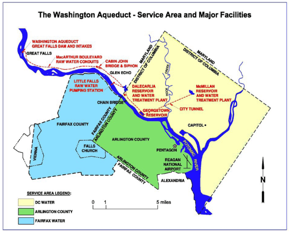
One of these I attended last year was to the Washington Aqueduct just north of D.C. This is a water treatment facility that produces drinking water for approximately one million citizens living, working or visiting in the District of Columbia, Arlington County, Virginia, and other areas in northern Virginia to include portions of Fairfax County (see map below).
I though a blog on this facility would broaden your understanding of the work USACE conduct if ever you work alongside them, highlight the unique water system that supplies Washington and how overall water treatment works if ever we as engineers have to work with such local infrastructure as the British Army did in Iraq or as 521 Specialist Team Royal Engineers did in Afghanistan in producing water from bore holes.
A division of the Baltimore District, U.S. Army Corps of Engineers, the Aqueduct is a federally owned and operated public water supply agency that produces an average of 500 million liters (135 million gallons) of water per day at two treatment plants located in the District of Columbia. All funding for operations, maintenance, and capital improvements comes from revenue generated by selling drinking water to the three jurisdictions. The aqueduct employs 150 USACE employees.
In the 1850s, the growing population of Washington and the memory of two devastating fires (one by the British; huzzah!) forced Congress to acknowledge that the nation’s capital required more than wells and springs to provide its water. In 1853, Congress commissioned a public water system and the US Corps of Engineers designed, built and, in 1859, began operating the Aqueduct.
Water Treatment Process
There are no great surprises for a RE with regards to the treatment. It is a pillow tank operation on a very large scale without worrying about the vehicle route and collection points. Raw (untreated) water contains suspended solids, sediment, bacteria, and microorganisms that must be removed to produce drinking water. These are removed by full conventional treatment, described below:
- Screening – On its way from the river to the Dalecarlia and McMillan treatment plants, raw water passes through a series of screens designed to remove debris such as twigs and leaves.
- Pre-sedimentation – While the water moves slowly through Dalecarlia Reservoir, much of the sand and silt settles to the bottom.
- Coagulation – A coagulant, aluminum sulfate (alum), is added to the water as it flows to sedimentation basins. Coagulants aid in the removal of suspended particles by causing them to consolidate and settle. Alum contains positively charged atoms called ions which attract the negatively charged particles suspended in water causing them to gather into clumps of particles heavy enough to settle.
- Flocculation – The water is gently stirred with large paddles to distribute the coagulant; this causes particles to combine and grow large and heavy enough to settle. This process takes approximately 25 minutes.
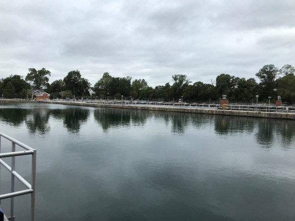
- Sedimentation – The water flows into quiet sedimentation basins (picure below) where the flocculated particles settle to the bottom. After about four hours, approximately 85 percent of the suspended material settles. The sedimentation basins can hold 166 million liters.
- Filtration – Water at the top of the basins flows to large gravity filters, where the water flows down through filter media consisting of layers of small pieces of hard coal (anthracite), sand, and gravel placed in the bottom of deep, concrete-walled boxes. Filtered water passes through to a collecting system underneath.
- Disinfection – Chlorine is added with precision equipment to kill pathogenic microscopic life such as bacteria or viruses. Ammonia is then added. The chlorine and ammonia combine to form chloramine compounds. The concentration of chloramines in the water is closely monitored from the time it is added at the treatment plants to points near the furthest reaches of the distribution systems. Disinfection is considered by many to be one of the most important scientific advances of the 20th century.
For the E&Ms. Orthophosphate is added to control corrosion in pipes, service lines, and household plumbing throughout the distribution system. It works by building up a thin film of insoluble material in lead, copper, and iron pipes and fixtures. This thin film acts a barrier to prevent leaching of metals into the water. Calcium hydroxide (lime) is also added to adjust the pH of the water to ensure optimal performance of the orthophosphate.
Due to geography and current infrastructure the aqueduct is the only source of water for D.C. The threat to the site by terrorism is considered and the aqueduct continuously monitors these threats with federal agencies, but the risk to the water supply through poisoning is low.

The blue pump is the one that supplies the White house and other key buildings. There are 6 pumps in total. 4 are required for daily operation so one can be maintained and the other held in reserve.
The biggest annual threat to water distribution is the weather. Temperatures can drop well below freezing, preventing water flow at the intake or even freeze the sedimentation basins; this is simply addressed by breaking up the ice with plant. A concern is that eventually, one winter may be too cold for this rudimentary system of ensuring drinking water and yet there is no plan B!
Historically, river solids removed during the water treatment process were disposed of by returning them to the Potomac River. This is no longer permitted. The Residuals Management Project involved the construction of equipment and facilities to collect water treatment residuals from three locations and convey the residual to a central treatment facility. At the central treatment facility residuals are thickened in gravity thickeners, dewatered by centrifuge, and loaded into trucks for off-site land disposal. This method of disposing to land fill is also becoming unsustainable due to environmental concern as is the cost of trucking the residue around.
Anyone with a sustainable solution to this problem should come forward as the aqueduct will pay a good prize.
Could the Royal Engineers provide drinking water to London? We may baulk at the thought but the question is unfair as the structure of both Corps of Engineers is vastly different. USACE alone is half the size of the British Army not to mention the expertise it contains in specialist roles. Maybe we can’t imagine RE operating a critical facility that supplies London but our RE are expected to provide potable water in wartime to a whole fighting force. Responsibility does not get much greater.
It was written above that the process is not much different than our current military transportable systems and how simple some of their process are in ensuring continuous water supply to the capital of the world’s biggest superpower. As future PE we should perhaps have the confidence that we could operate such infrastructure alongside local contractors.
Automated Construction
I stumbled across this through one of our clients and thought it was worth a comment. I’ll keep it brief and let the video do most of the explanation using nice clips the E&Ms should be able to follow.
The video shows an interesting idea for economising on the construction of simple steel frame/concrete slab type buildings. Using segmented off-site manufacturing and simple floor plate design, this method enables considerable increase in the automation of steel frame construction alongside simplifications in temporary works. Read more…
Temporary Works Tour: 1-5 Grosvenor Place
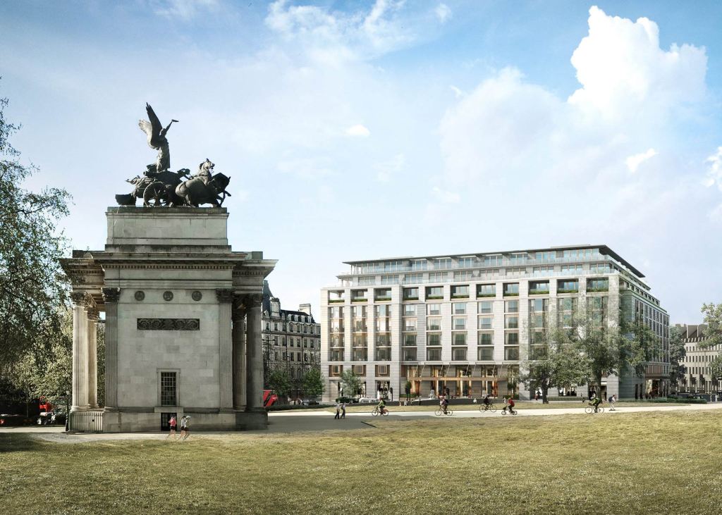
I recently visited a project in London where Sir Robert McAlpine Design Group are the temporary works lead. The project is to build a new hotel/apartment building near Hyde Park at 1-5 Grosvenor Place for Hong Kong and Shanghai Hotels. The building comprises 9 floors above ground and four to five basement levels below. As the basement construction period is significant due to the complex below ground structures, and the volume of material to be excavated and removed from the basement, the method of construction has been ‘top down’. This allows for the basement to be excavated and constructed concurrently with the superstructure construction and fit-out above, with savings to the programme. The building comprises four reinforced concrete ‘cores’ in each quadrant of the building which provide the main vertical access with a central courtyard in the centre. The central courtyard is currently used as the access for plant and material to the basement levels during construction, but will be covered by a garden on completion. The main structure has been completed with the first floors now being clad. The last two floors of the basement are currently being excavated down to approximately 20m below ground level.
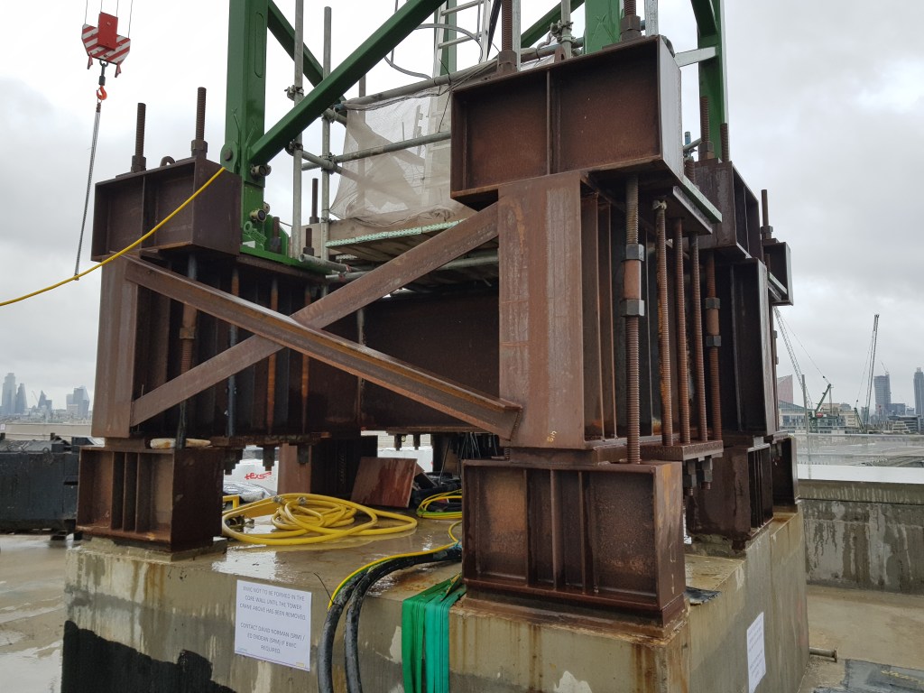
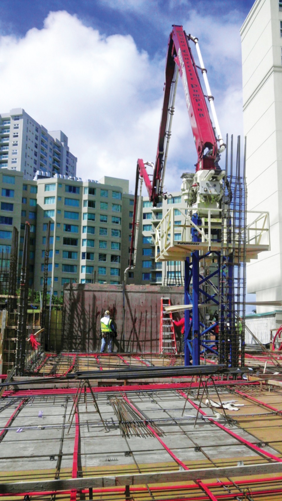
The temporary works on this project have been significant and I thought I would show the extent of them here. At each core of the building a crane has been placed on the roof. Placing cranes on the cores allows the building to be substantially completed and made watertight without having a void through the building for the tower crane mast. This has required a temporary works solution to provide a base to fix the crane. The supporting concrete core has been designed and enhanced to withstand the tensile stresses caused by the crane which has required bursting steel reinforcement. Note also the long post stressed threaded connections which are required to take the tensile stresses of the crane.
The site itself is very restrictive with very limited space for site offices. The solution has been to construct offices cantilevering out over the adjacent carriageway with a steel frame to support the offices above. To limit the loading on the pavement on which it is founded, a reinforced concrete raft has been cast over the pavement. Access positions have been required at any existing manhole or service cover locations. Further resistance to overturning has been provided by casting holding down bolts into existing grouted or concrete filled vaults below. The limited space has also required a solution for site traffic. This has been overcome by constructing a temporary steel structure to support a ramp and bridge through the courtyard of the building.
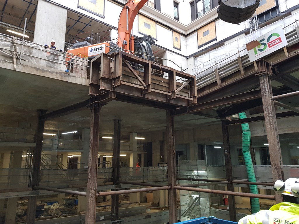
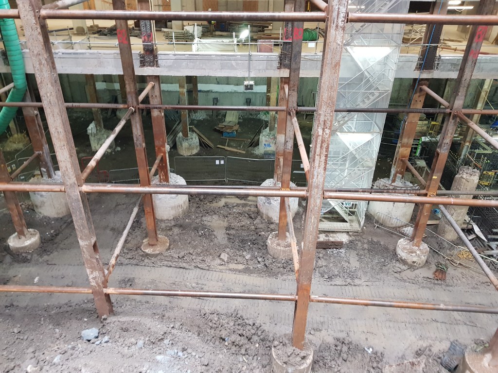
The steel structure is supported by large plunge columns that will eventually be removed and cut at pile cap level (see columns highlighted in green in the drawing below). The ramp and bridge allow site traffic to enter one side of the building and exit the other. A telescopic clamshell bucket shown in the image above is able to extract the spoil from the basement levels below and load it onto trucks passing over the temporary road structure.
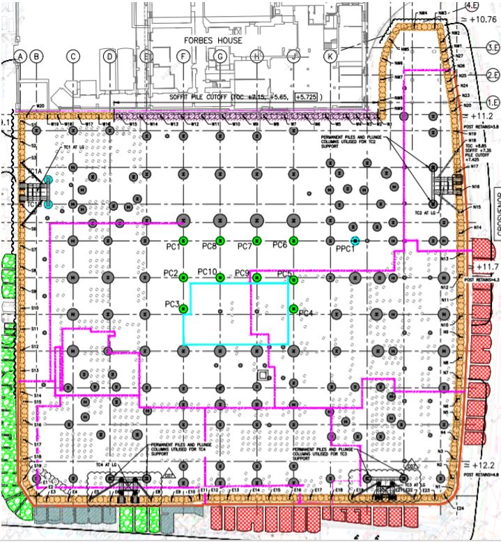
At basement level 1.2m diameter secant piles have been installed around the whole perimeter of the site (orange above). In particular propping has been required to strengthen the piling on the west end of the site where another building abuts the site closely (purple line above). This has been to limit the deflection of the secant piles and therefore limit the effects on the adjacent structure. Inclinometers have been installed down the length of these piles to monitor any significant deflection.
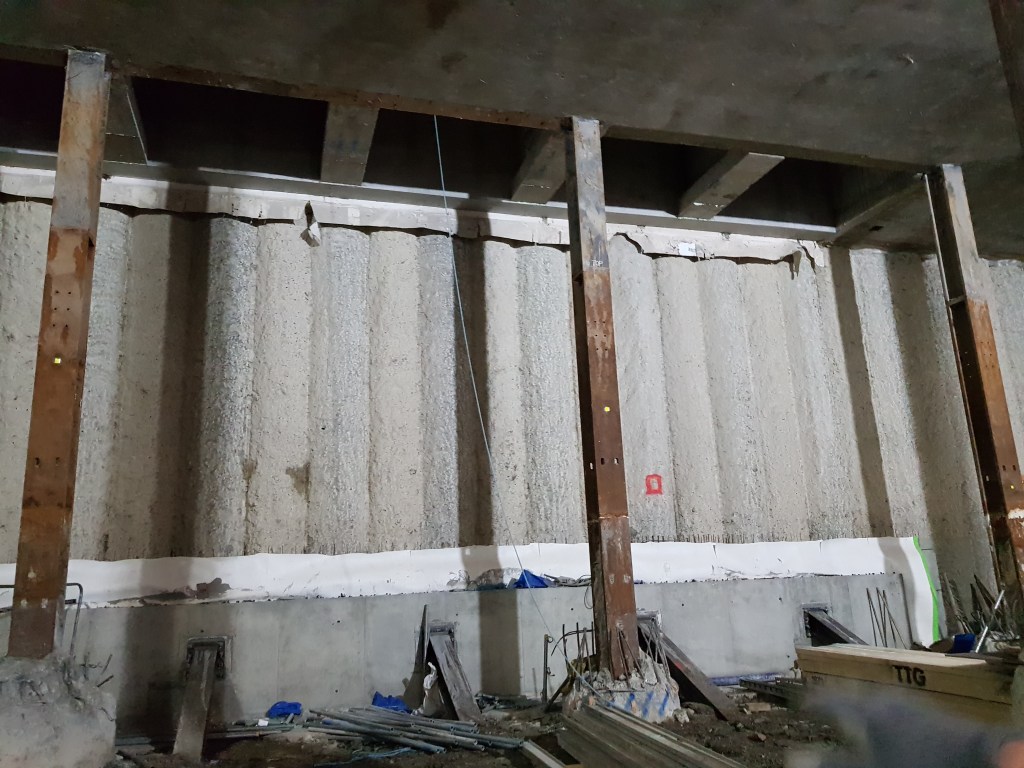
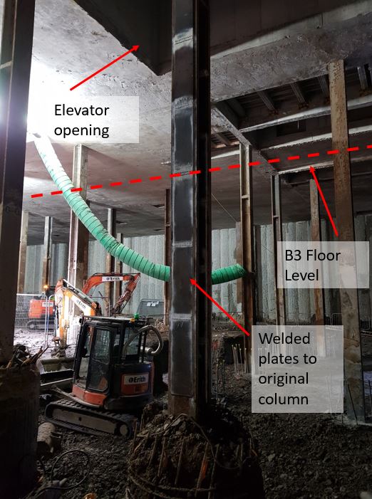
The basement is currently being excavated over the final two floors. This has been in order to enable large sized plant to operate and to allow removal of adequate volumes of clay per shift. Originally the design of the building only included three basement floors as planning permission for a fourth had not been granted during the design phase. However, later during construction a fourth basement floor was approved. This caused an issue with some of the existing columns that had already been installed. They would be too slender to take the loads from above in the temporary state before basement level 3 had been constructed. The increase in effective length between B2 and B4 level meant that some of the columns would need to be modified. In the image below shows where additional plates have been welded to the flanges of the columns to make them stockier and reduce their slenderness ratio.
The columns at higher level were originally to be encased in reinforced concrete. However, this has recently changed as the client now wants a masonry finish to the columns. This means that the cross sectional area of the columns are reduced, thus a reduction in the second moment of area. My involvement with this project so far has been to evaluate whether the columns are able to still take the axial loads without this reinforced concrete encasement.
This demonstrates the significant amount of temporary works involved in a project of this size, especially in a congested site like London. This offers some excellent opportunities for an engineer to get experience on a wide variety of engineering challenges.
Technical Information Management
Having left my Phase 2 site last month I reflected on the number of IT systems used and wonder what the military should learn from rather than copy. I observed the following:
- Drawing Management. A single repository for all technical drawings that can be accessed by all stakeholders (Designers, T1 contractor, Client, Project Verifier and Sub-contractors) is an efficient way of ensuring all parties have access to the latest drawing versions. The project used a web-based IT system called ACONEX which can be accessed from any internet-connected device (including mobile telephones and tablets on-site). It has a good search feature that displays all drawing revisions so changes are easily identified. Updates to drawings are notified as transmittals with all parties informed as automatically part of a mailing list. The disadvantage of the system is that not all stakeholders are willing to use ACONEX to share information (external stakeholders often revert to email) which increased the burden on the on-site team to update the drawings stored within ACONEX to prevent information becoming outdated. As the transmittals are not individually targeted or area-specific, it was easy to miss key information due to information-overload and the requirement to manage multiple IT system inboxes. Overall, I believe ACONEX fulfilled the drawing management role well for large scale projects when it is used correctly by all stakeholders and appropriately resourced with a dedicated document controller. For military projects, the same effect can be achieved via SharePoint and email.
- Formal Messaging. ACONEX also has an email/messaging capability but unlike email, every message is serialised, cannot be deleted and is viewable to all project users. These features are both advantageous and disadvantageous across a range of safety, legal, quality and commercial issues. The system enables collaborative working as all staff have access to all information which is handy when individuals are on leave or out of the office. For these reasons ACONEX messaging was accepted as the formal notification system within the project contract and is used for all formal correspondence, Requests for Information (RFIs) and recording key decisions. Another disadvantage of the system is the requirement for individuals to manage an additional system to their email. ACONEX is a good system for formal messaging on large scale projects however for military projects the same effect could be achieved via a formalised written letters/memos emailed to parties with pdf copies uploaded to SharePoint.
- Collaborative Working. Every organisation involved within the project has their own data repository where information confidential to the organisation can be stored and accessed only by members of the organisation. Examples of this include commercially sensitive information, interim programmes, work in progress (WIP) and interim quality records. The project used SharePoint to enable collaborative working across the Alliance Partners as this avoided server access issues. The software is fit for this role but the effectiveness of information access on-site was limited by the different companies’ technology hardware and individual user software licences. SharePoint is already used by the military for in-barracks data storage. Unfortunately, some deployable IT systems are dated and do not have this capability or lack internet access. Where this is the case, files are shared via local network storage devices or transferred between individual computer storage. In these instances, version control is essential; significant time and resourcing must be devoted to data management practices. The user is responsible for the archiving of data beneficial to future business output but this vital step is easily missed; as highlighted by the 2018 TICRE data amnesty at 170 Engineer Group, which identified significant gaps between the data held by TICRE and the individual Works Groups.
- Company Developed Software. The project used a JH online application (Project Pack Web) to record and track key project information useful to business output. The application was used for procurement, risk management, environmental monitoring, and quality records. The Client and Project Verifier had limited access to the quality record element for the notification and release of hold and witness points. The system allows JH’s regional business team to monitor key information required for business output in the same way that Brigade and Divisions can view Unit information within ODR and JAMES. Work Lots were used to group all relevant information for a specific work activity into one record for ease of reference. This included Activity Method Statements (AMS), ITPs, checklists, permits, defect lists, hold and witness point approvals, materials, sub-contractors and related works. The Work Lots form the basis of the Client’s handover file at the end of the project. The advantage of this application is that the regional business has visibility of project information, Work Lots are generated as part of day-to-day activity and in-house software can be adapted to meet the needs of the project. The disadvantages are more bugs compared to commercial software and it can be clunky to use. Unfortunately, the system was not used to its full potential and there are some areas that failed to provide adequate functionality resulting in duplication of data. JH is currently involved in a number of JVs and partnerships where different IT systems are used. This reduces JH staff familiarity with in-house software causing skill fade and additional training requirements. For large construction projects, PPW type software has significant utility and if properly resourced and developed. The majority of military infrastructure projects have simpler quality requirements and use existing defence procurement systems. In the military context, it would be more cost-effective to identify appropriate Work Lots at the start of the project and use an electronic file structure to archive quality records. The tracking of other key resources and data can be achieved via spreadsheets on SharePoint or a local area network.
What are your experiences from Phase 2? Has anyone come across any better systems for use in a military context?
Buildings as ‘urban mines’
On the same vein started by Ali wrt sustainability – a short read from the ‘lefties’ at the Guardian that I found interesting:
The construction industry accounts for 60% of new materials used, a third of waste and 40% of the carbon emissions. A few countries are starting to turn construction into a circular process, with ideas such as ‘building passports’ detailing every component for future re-use; ‘building elements as a service’, with ownership retained by the manufacturer and buildings never truly ‘owned’; and old buildings being ‘mined’ for useful materials.
In my (short) experience so far in a city based Phase 3 – the lack of space means that many of the projects are ‘re-imaginings’ of a current, in-situ structure. That being said, the place is gutted and, with a Client focus on ‘going green’, replaced with facades and services to achieve 6-stars (GreenStar). In this way Sydney is slowly upgrading its ‘old’ stock (bear in mind many of the buildings are less than 50 years old, modern Oz is young!) and improving its green profile.
Has anyone found this to be a trend in other major cities, or indeed wider? I get the impression that Europe is leading the way.
For those with experience with the RSME refurb – did they consider sustainability, or was it a ‘lick of paint’ for those old, drafty buildings?
Cost of Over-specification

High-Rise Concrete Pump Cleaning…How?
Walking around the high-rise construction in Melbourne I’ve been asking myself one question… How do they clean the static boom pumps and concrete lines after a pour? I know significant ALC charges were incurred for not cleaning the ANEMOI Volumetric mixers properly before shipping them back to the UK.
At Batemans Bay we cleaned mobile boom pumps via ‘blowing out’ into skip bins and washed water through the discharge hose but I’m guessing this isn’t practical in vertical construction.
When using a fixed/hardline pump a foam ball was forced along line at the end of the pour to remove all the concrete so the line could be left in place. I’m guessing a similar approach is used in high-rise construction. Does anyone have any experience or insight?
Another question I’ve been pondering is how are the pumps stages increased? Do you have to strip the top section and use a tower crane each time you increase a floor?
“Optioneering Study” – Drake Island Luxury Hotel and Spa
The What & Where
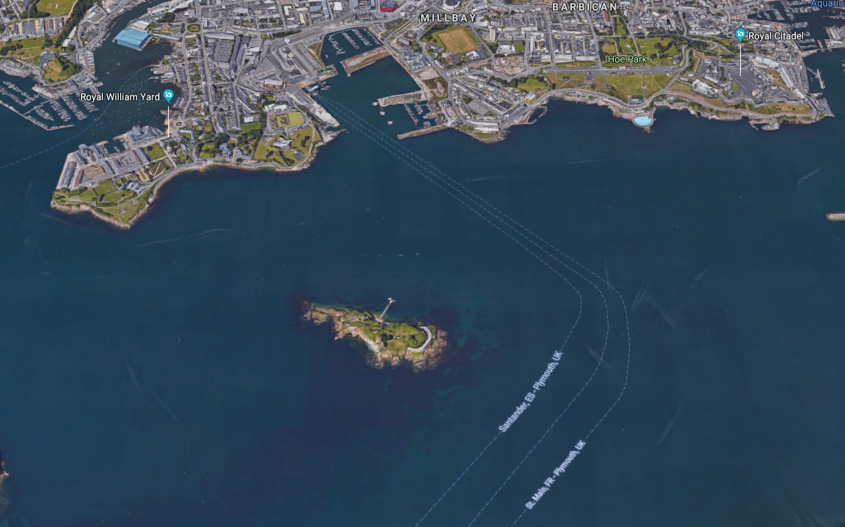
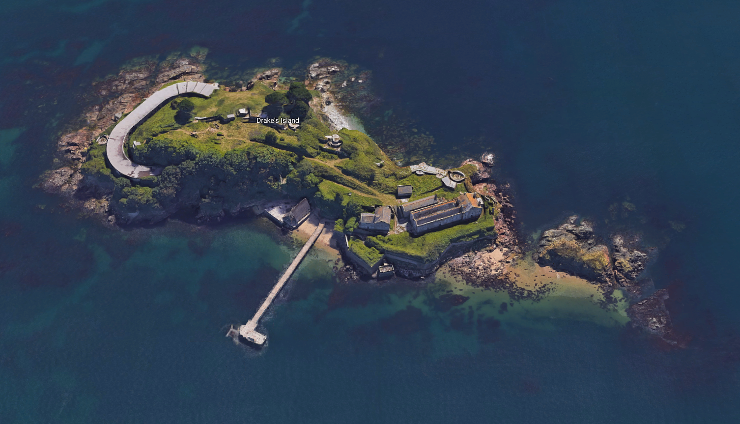
Having settled into my Phase 3 placement at a Plymouth based Building Services Design consultancy, I’ve been given ownership of a very unique project. Guardian Industrial UK (GIUK) as the client have purchased “Drake’s Island” sat in the middle of Plymouth Sound with a view to transforming it into a luxury hotel, spa and visitor centre/museum.
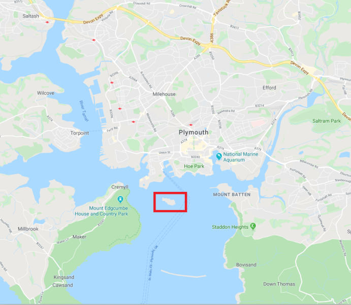
The six-acre plot is around 600m from the Plymouth shoreline and has a long history of being used as a Military defensive base . Originally constructed as a defensive fortification in the 16th century, it was also used extensively in both World wars to protect Plymouth’s Naval fleets. It was then used by the military as an Adventurous Training facility until it was closed down in 1989. Luckily Rob managed to get his Canoeing foundation qual there in 1988 before it closed. He hasn’t been to sea since.
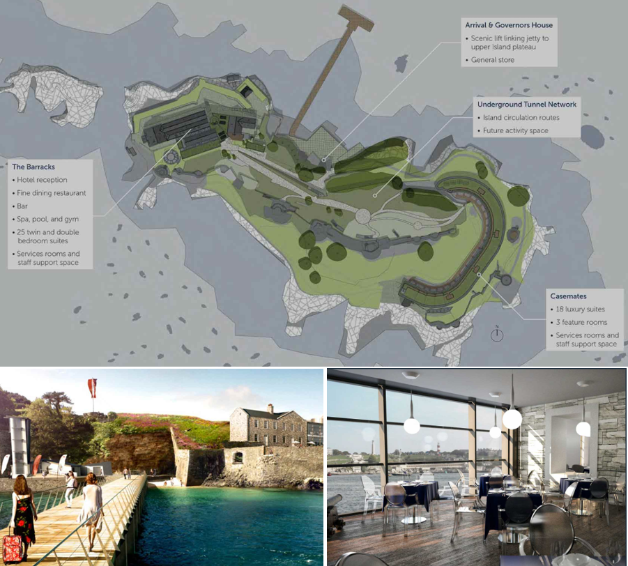
The Vision
I have a meeting with the client next week to try and tie down the scope. His intent at the moment roughly is shown below:
Restrictions
At present the site is derelict and pretty run-down. All buildings are Grade II listed and the island is home to endangered seabirds, fancy sea-weed and other rare aquatic wonders. The client has also stated a desire to make the island self sufficient through the use of renewable energy. Did I mention…
- The EA will not authorise a discharge permit for treated water (or so I’m told)
- Any untreated biological waste must be removed from the island EVERY 24 hours
- No diesel generators allowed at any time
- No outdoors areas are available to place additional infra
- No lift capability to move anything up the 12m rocky bluff perimeter, and no dedicated lay down areas
- The shallows/shoreline is off-limits
Pre-existing services:
Incoming electrical supply: 1 x 11kV submarine cable, laid in 1982, recently tested and ok but liable to deteriorate.
Substation and distribution: None
Incoming gas supply: None
Incoming water supply supply: None
Waste water treatment: None
Waste water disposal/sewers: None
Data/comms: None
The task:
So provide EVERYTHING to a place that effectively has NOTHING. Cool.
I’d imagine over the years that there have been similar challenges presented to RE officers when operating in different corners of the world.
My immediate thoughts are;
- Power
- Utilise the incoming supply with a pair of 11kV:400V “environmentally friendly” silicone/ester/resin filled transformers. This will be needed for all enabling/perm works and lighting from the outset.
- Research into “battery powered buildings” for renewable energy storage, design in low energy options to reduce load profile.
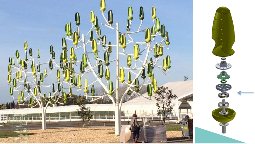
- Consider options for on-site generation such as “wind trees” and “bio-CHP”
- Water source
- Bore hole?
- Desalination plant?
- On-shore supply via pipeline installation?
- Waste water
- Will need to be taken away – heavy logistic burden
- Potential for treatment and recycling?
- Get on-site treatment right and renegotiate with EA for discharge licence?!
So I’d like to put it to the floor… has anyone seen examples, or been part of a team, required to deliver works/services/energy needs in particularly remote places? What advice would you give?
Or just any innovative suggestions to help me out (tech and/or logistics)?!
Phase 3 – Total Recall
I have recently moved from Gatwick Airport to start work at Sir Robert McAlpine Design Group in their Temporary Works team. I’m still in the first weeks here but have already been given quite a few tasks to work on. It’s certainly been a challenge to recall the lectures and read my notes from phase 1 and apply them to practical examples! I thought I would share some initial observations early days.
Some of the tasks I have done already include designing a concrete lintel for an opening including props to enable the lintel’s installation. I have also done buckling checks on plunge columns (not strictly temp works…) which has had me looking over some of the worked examples and exercises we did in phase 1. In particular have found that using the IStructE Eurocode guides and just asking around the office has been helpful. It seems that the design team here prefer to do a lot of design by hand on calc paper almost exactly the way we have been taught in phase 1. The team also use quite a bewildering number of software programmes to check the calcs. However, Robot and MasterSeries seem to be the most useful. Robot in particular for frame, slab and plate analysis, MasterSeries for connections and capacity of steel members. I have also found that BeamPal is quite useful for doing simple bending moment and shear force checks of beams.
For those about to go onto phase 2 and then phase 3 at the end of the year I hope this shows that what we learn is put into practical use in industry. Also it might prove useful for future students to gain a working understanding of software they use.
