Archive
Eurocode Simplified?
A quick one for the civils (and maybe even the E&M’s if you ever get asked to look at a future civil problem…).
When working on my thesis I stumbled across this website: EurocodeApplied. Basically, it provides free online calculation tools for structural design to Eurocode. You select the relevant check, enter your input data and select any relevant National Annex limitations. It also summarises key data from the code without having to find every table or figure.
There are pages for EC1 – Actions (including wind actions), EC 2 – Concrete (creep, shrinkage, durability, axial and bending checks, shear design and detailing), EC3 Steel (steel properties like the blue book and section capacity checks) and EC8 Seismic (actions, fundamental periods, reductions of earthquake actions during construction and foundations/retaining structures).
Sadly I’m not doing any design to EC over here so I’ve not been able to validate their accuracy. If any of the Civil crew are doing wind loading or simple checks and want to try them out I’d love to know if they are a good source. If validated, it could be a really useful tool for future PET or Clk Wks students depending on how kind the PEW lecturing staff are feeling!
Model in your hands
One of the projects being delivered by Arup has made use of QR codes on their design drawings to bring them to life.
You can scan the code on the drawing set with your phone camera and get automatically re-directed to a snapshot of the BIM 3D model. You can then ‘look around’ using the motion sensors in the smartphone. An example is here.
Anyone with the design drawing and a smart phone has access. Great for coordinating with a sub-contractor on site without having to be in an office with access to the software and model files.
Has anyone else spotted any novel uses of BIM/3D models?
Filling the Royal Docks
I have been tasked with the assessment of the feasibility of infilling part of the Royal Docks with material reclaimed (almost all fines) from the surface of a site adjacent to the site. This is to maximise the available land on the site and reduce the need for offsite disposal. Beckett Rankine have been tasked with working out how this can be done prior to it being tendered as a D&B contract.
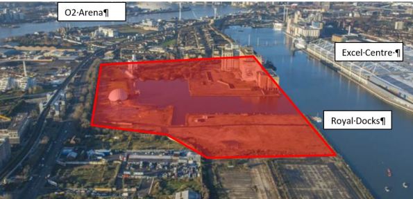
Site Overview.
The problem is they want to infill this part of the dock:
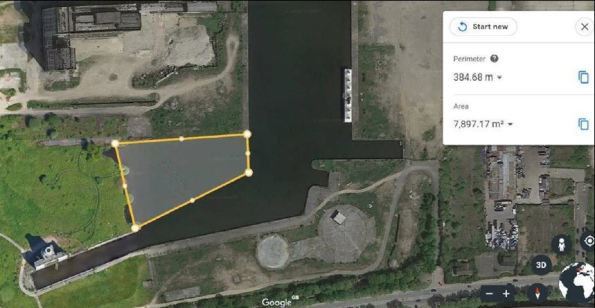
The surrounding walls on the north and west of the site are in horrible condition so can’t be relied on for support. We are required to provide a high-level concept design of how this can be done.
The ground conditions are:
- GL is at +5m
- Water level is around 4.2m – 4.8m depending on the dock level.
- Made Ground, Alluvium and dock sediment down to about -3.8mOD
- River Deposits _1.5m to -6m (+7m head on GWT, probably governed by the Thames and more importantly the adjacent dock!).
- Lambeth group -6m to roughly -16m (acts as a cut off between hydro regimes)
- Thanet Sand -16m to -29m
- Chalk -35m to -38m
Currently we have 3 options:
- Double skin sheet piled wall (like they have used on Tideway structures on the Thames), dewater inside, then infill.
Pros:
- Structure will be strong enough to support the large lateral water pressure.
- Will allow access to what the cofferdam so the alluvium at the bottom can be removed
Cons:
- Large costly structure requiring material to be brought on site as the infill.
- Large single wall, either contiguous or sheet pile, dewater, then infill from the bottom up.
Pros:
- Much simpler structure.
- Will allow access for personnel to compact layers and remove alluvium.
Cons:
- Continguous piles are unlikely to keep the water out. Large pumps will be required.
- Sheet piles will have to be large to avoid potential buckling.
- Sheet pile, then don’t dewater, remove the dock sediment by dredging, then just infill and vibro compact and use displacement to get rid of the water.
Pros
- No dewatering
Cons
- Not easy to remove alluvial filth at the bottom of the dock.
- How to effectively dewater the fines and prevent long term settlement
The key issues we are having are:
- Identifying which would be the best structure?
- How to ensure that the fines being used as infill are suitably compacted or stabilized to avoid long term settlement?
Anyone got any words of advice or any other similar projects they have come across?Currently we are investigating what has been used for land reclamation techniques on the Thames Gateway, Dover extension and Tideway.
Powerhouse
Thought I’d share an interesting and beefy mechanical services problem I’ve been landed with over the last few weeks.
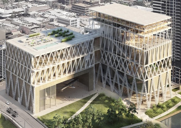
Following a successful competition bid, I have been placed on the ‘Powerhouse Museum’ mechanical services team.
The Powerhouse is a new event/museum/art space project (think a mix between Science Museum and the NEC) that forms the ‘largest investment in culture and the arts in Sydney since the Opera House’ and has a budget of around AU$400m.
We’re at the very early stages of design and I’ve just finished knocking out the initial space conditions appreciation for the internal space in an attempt to provide some plant massing figures for the air handling plant.
All I’ve had to work with is a rough layout from the architect, depicted on ‘Rhino’ (coloured blobs depicting rooms/areas) and a very ‘strategic level’ project brief.
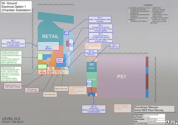
It quickly became apparent that there are some significant issues with what the winning architect wants, what is physically possible and what the Client (Govt. of NSW) can pay for. Not only has the building envelope shrunk by 30% whilst the expected space populations remain unchanged, the control level for the spaces is to the ASHRAE ‘AA’ standard (rigid temperature and moisture control to protect sensitive artwork).

Helpfully the architects have allocated less than 1% of the floor area to plant space and are appalled that we may request more. Considering the location (summer 40+ degrees and high humidity) and the fact that the façade is all glass…my numbers are coming out silly sized!
Taking the largest presentation space as an example – the space is approximately 3000m2, with a floor-to-ceiling height of 30m. Current plans have this space with a peak population of 5000 people (0.5m2 per person).
I’ve had to make some pretty savage assumptions to ensure the entire structure isn’t just filled with plant:
- Firstly, the assumption that the population will reduce, so I’ve been modelling at 50% occupancy relative to the original value
- Secondly, we will only be treating the lowest 4m of the room
Even with this, to ensure minimum indoor air quality I need to deliver over 40m3/s of cool air to the space. This OA requirement, coupled with the estimated heat gains, sees a cooling load in the order of 1.4MW; and this is one of seven presentation spaces.
Another big issue is how we deliver the cooled air to the space. With a 30m high space, the means of controlling the mixing with the layer above 4m, which will have its own humidity, temperature and stratification presents a problem for control. ‘Top down’ delivery sees the air thrown 26m before it reaches the 4m layer to be cooled. I conducted a benchmarking exercise against other museums, which seem to favour floor level grills. These require thicker walls for the ductwork – however the spaces they are used are kept relatively small and are located at the core of the building to assist the plant.
What is inflating the numbers is the rigid control class and the population – these are our first targets to ‘manage’ with the architect. I get the impression that this is a once in a lifetime/legacy project for them and the museum curators; as such they’ve asked for all the bells and whistles.
Thankfully, the Client has appointed Arup directly – so there’s some leverage to play with when interacting with the JV of French, Japanese and Australian architects!
Does anyone have experience of controlling temperature in very large spaces? I’m thinking that airports will have similar volumes, albeit with more flexible control regimes. Can you throw air that far, still maintain control and not ruin the comfort conditions with the effects of draft?
An unexpected risk?
Has anyone’s consultant issued guidance following the Covid-19 (Coronavirus) outbreak?
My consultant is owned by a Singaporean holding company. Their business stragtegy is to create a consultancy powerhouse in Asia so the outbreak is ‘bad for business’. Already, they are reporting that the virus will have a significant impact on this years profit figures. (The financial year runs Jan-Dec over here).
What I have been most surprised and impressed by is the direction all employees of the holding company have been directed to take. It was almost like military orders! A range of measures have been implemented to protect employee welfare/health and safety and to mitigate further business impacts including:
- Cancellation of all non-essential travel to China, Hong Kong, Singapore etc.
- Authority to travel to these countries is required by company CEOs.
- 14-days self-imposed quarantine (working from home) for all employees who travel through or have close contact with people travelling through the countries above.
- Doctors note required before returning back to work.
- Workers in affected countries are all working from home to minimise further spread of the virus.
Interestingly there was due to be a large formal dinner planned next week for all elements of the Singapore business and the senior management of companies outside of Singapore. This was postponed (prior to Singaporean guidance to avoid large gatherings) because the cancellation fee was considered a small price to forefit compared to the risk and cost to the business if the entire senior management became incapacitated. All staff were informed of this decision in a direct email from the CEO explaining why the decision was being made.
I know John Holland have long had a policy of senior management travelling to meetings via different flights so an accident would not wipe out the entire senior management and to maintain avaliability of business leaders at all times. This us a very similar concept to not having the Commander and 2IC permanently co-located on the battlefield.
Our office was also due to benefit from a surge of structural engineers for a couple of weeks from a JV partner. The extra engineers were due to arrive from Hong Kong but with the 14 day quarantine requirements this is now up in the air. Wider project impacts are yet to be determined.
Aware this topic is probably ‘closer-to-home’ for the Australian crew but I’m wondering if any of the UK companies have implemented business continuity plans or if it’s not on the radar. Any thoughts?
Return of EFC
For those who have read Tom’s blog about EFC this is just a small addition as you can’t add photos to comments it needs its own post. For those who haven’t read Tom’s either go back and read it or ignore this one as I won’t waste time regurgitating what he articulated better than I could and it won’t make sense unless you have.
Basically BAM sent out a message to us temporary works designers encouraging us to use EFC in our designs. It seems that due to lack of codes or experience with it they are not confident on recommending it to larger permanent jobs but they think the temporary works environment is a perfect start for its incorporation. We have been sent both Wagners (Toms post) and CemFree brochures to read. They both offer similar properties and savings.
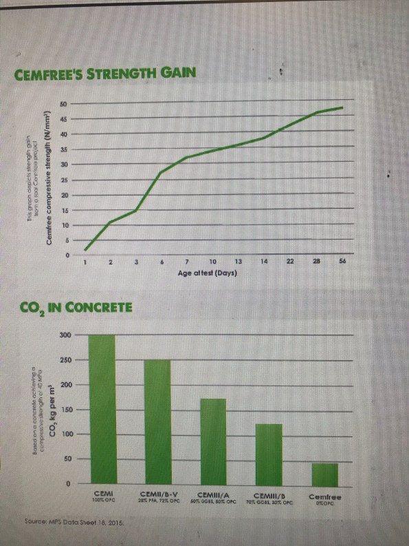
That is the strength and savings promised by CemFree for their product.
The fact BAM have suggested it for temp works first is either due to the lack of risk on our designs (perhaps due to the perceived inefficient low risk designs produced by temporary works designers) or maybe they have worries about its durability.
CemFree advertise a coastal defence job used in Harwich using 100% EFC saving a staggering 88% in embodied carbon, they clearly have no such worries on durability.
I do wonder if the H&S of using AACM instead of cement powder is advantageous as well as there is no mention of the dangers of its powder form on either companies brochure.
Removing the Toe
Just thought I’d post a quick blog about some geo stability issues we have been conducting recently (should get some flashbacks of Phase 1!).
We have just completed submissions of three Preliminary Design (PD) packages for three bridge widening design packages as part of the Monash Freeway Upgrade in Melbourne (see my last blog for details for those interested).
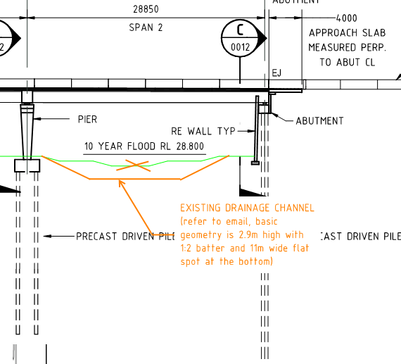
Some new information recently came to light regarding a recent channel construction by Melbourne Water between a pier and abutment of one of these bridge’s substructures (Officer South Road Bridge – East Abutment)
The earthworks undertaken as part of the original construction for this bridge included the excavation of a 1.2-1.8 m deep open channel drain between the central pier and eastern abutment. It has now come to light from the Principle Contractor (our client) that this channel has recently been augmented to cope with increased flows.
The recent works have increased the channel depth to 2.9 m and the channel now occupies most of the space between the pier and abutment (11m bottom width and 22m surface width). The newly supplied drawings show a 3 m gap between the abutment wall and the crest of the channel and indicate a battered slope of 1V:2H.
Previous assessments of the abutment/reinforced wall were not available at the time of the PD report preparation and so the impact of the 3 m deep channel excavation was not assessed. There is also no understanding as to whether the global stability of the abutment was considered by the party who extended the channel.
An assessment of this, and the effect on the design we tendered for were not part of the scope, meaning we are now awaiting decision from our client on how to proceed (variation to our scope/contract, use another (specialised) consultant to conduct an assessment, etc.).
To gain an understanding of the global stability effects and impact of the earthworks, we decided to conduct a quick preliminary assessment of the GEO stability of the abutment prior to, and following, the 3 m excavation. The assessment for now only considers the long-term stability the stability during construction will need to be assessed too – but time is money… so we aren’t exactly quick to conduct an assessment).
To do the analysis, we used ‘GeoSlope 2019’ software, which is rather like the software we used with John Moran in Phase 1 (the name of the software escapes me…). The screen shot below demonstrates the ground model and parameters used, which has been taken from borehole data and a geotechnical investigation report.
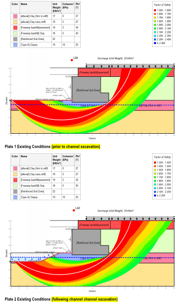
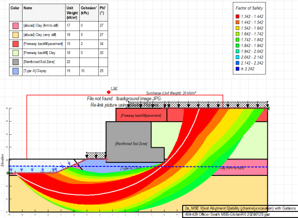
The results of the analysis show that removing the soil at the support will likely reduce the FOS to 1.3, is below the 1.5 figure preferred here. However, saying that, the model has some assumptions, which could be refined by a more detailed geotechnical analysis and could consider the effects of the piles resisting the forces within the slip plane – though I believe we will now need to consider the shear/bending effects this will have on the piles which could up the reo and increase cost to the client.
We also modelled the use of gabion walls in front of the abutment (shown as a surcharge in front of the abutment), but the analysis showed a raise of only ~0.4 FOS.
I suppose what has been alarming to me is that, by all accounts, no check was conducted by the contractor responsible for excavating this channel – it appears they have blindly excavated without consideration to how the soil in front of the abutment is providing passive resistance to the abutment toe.
As this information was not provided during tender, the risk is with the client. i.e. do they want to conduct a more detailed geotechnical investigation to refine the model? Do they want design work conducted to improve the geo stability of the abutment? We shall see.
Anyway, just a little snap shot of some geo stuff we were exposed to on Phase 1 that I’ve had the chance to utilise during Phase 3 (which as a bit of a surprise working in the superstructures side of things).
Planning for future sustainability?
I often think of sustainability as the design decisions made to balance the social, environmental and economic cost if construction. Often engineers look to reduce material consumption through design but how often do we design for disposal.
Linked to the theme of building being material banks is this BBC article on the disposal of wind turbine blades. The turbines built in the 90s are now over their 25 year design life but the materials selected for their mechanical properties are proving difficult to recycle. You can read more at the link below.
Food for thought perhaps?
BBC News – What happens to all the old wind turbines?
https://www.bbc.co.uk/news/business-51325101
Fire system site survey
Just had a meeting with the estate and facilities manager at the local university regarding their fire system and emergency lighting coverage. They require a survey followed by a design proposal for a possible upgrade if funds allow.
They have 4 buildings that require an upgrade but they do not know to what extent. As a cost saving measure they seem very keen to use any existing cabling (their suggestion, not mine). I explained that in theory this is fine as long as the existing cables meet the current standards but there is a risk as I, as the designer and individual who will conduct the survey, cannot comment on the integrity of the existing cables within the installation.
I have advised against this but they wont drop it, anyone else have any similar experiences?
Limit State vs Permissible in temporary works
I’ve just designed a temporary timber hoarding using limit state and BS EN 1995 expecting a lolly pop at the end because I “did it thoroughly and correctly” only for the checker to be annoyed they now have to learn 1995 and they can’t use the TWf guides and our internal “cheat sheets”.
I naively thought the choice between design methods was between the stuck in the past engineer vs the modern engineer but I was very wrong. It seems that a lot of the stuff in temporary works is designed using permissible but not all of it.
Anyone have experience with having to chose between the two for temporary works?
I could have designed the hoarding in half the time and probably would have got the same design (maybe my ply would have been 2mm thicker). It’s a balance between design risk and efficiency which temporary works walks a fine line across.
