Removing the Toe
Just thought I’d post a quick blog about some geo stability issues we have been conducting recently (should get some flashbacks of Phase 1!).
We have just completed submissions of three Preliminary Design (PD) packages for three bridge widening design packages as part of the Monash Freeway Upgrade in Melbourne (see my last blog for details for those interested).
Some new information recently came to light regarding a recent channel construction by Melbourne Water between a pier and abutment of one of these bridge’s substructures (Officer South Road Bridge – East Abutment)
The earthworks undertaken as part of the original construction for this bridge included the excavation of a 1.2-1.8 m deep open channel drain between the central pier and eastern abutment. It has now come to light from the Principle Contractor (our client) that this channel has recently been augmented to cope with increased flows.
The recent works have increased the channel depth to 2.9 m and the channel now occupies most of the space between the pier and abutment (11m bottom width and 22m surface width). The newly supplied drawings show a 3 m gap between the abutment wall and the crest of the channel and indicate a battered slope of 1V:2H.
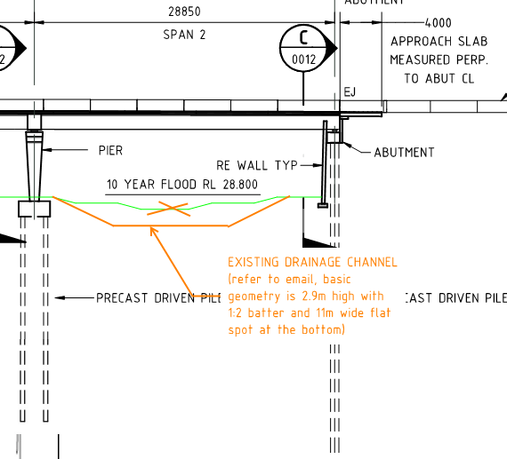
Previous assessments of the abutment/reinforced wall were not available at the time of the PD report preparation and so the impact of the 3 m deep channel excavation was not assessed. There is also no understanding as to whether the global stability of the abutment was considered by the party who extended the channel.
An assessment of this, and the effect on the design we tendered for were not part of the scope, meaning we are now awaiting decision from our client on how to proceed (variation to our scope/contract, use another (specialised) consultant to conduct an assessment, etc.).
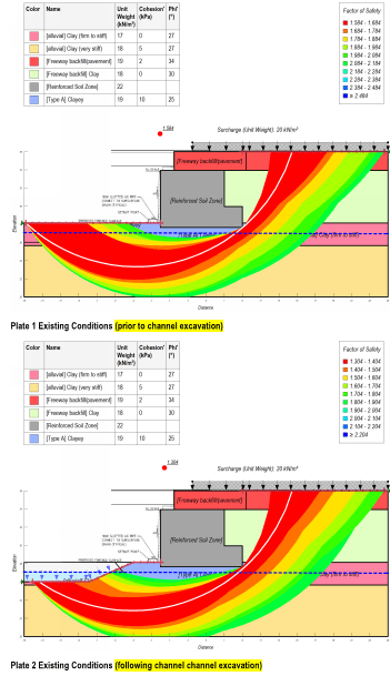
To gain an understanding of the global stability effects and impact of the earthworks, we decided to conduct a quick preliminary assessment of the GEO stability of the abutment prior to, and following, the 3 m excavation. The assessment for now only considers the long-term stability the stability during construction will need to be assessed too – but time is money… so we aren’t exactly quick to conduct an assessment).
To do the analysis, we used ‘GeoSlope 2019’ software, which is rather like the software we used with John Moran in Phase 1 (the name of the software escapes me…). The screen shot below demonstrates the ground model and parameters used, which has been taken from borehole data and a geotechnical investigation report.
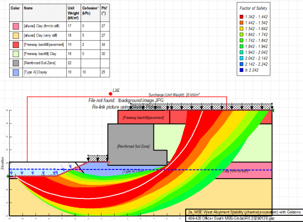
The results of the analysis show that removing the soil at the support will likely reduce the FOS to 1.3, is below the 1.5 figure preferred here. However, saying that, the model has some assumptions, which could be refined by a more detailed geotechnical analysis and could consider the effects of the piles resisting the forces within the slip plane – though I believe we will now need to consider the shear/bending effects this will have on the piles which could up the reo and increase cost to the client.
We also modelled the use of gabion walls in front of the abutment (shown as a surcharge in front of the abutment), but the analysis showed a raise of only ~0.4 FOS.
I suppose what has been alarming to me is that, by all accounts, no check was conducted by the contractor responsible for excavating this channel – it appears they have blindly excavated without consideration to how the soil in front of the abutment is providing passive resistance to the abutment toe.
As this information was not provided during tender, the risk is with the client. i.e. do they want to conduct a more detailed geotechnical investigation to refine the model? Do they want design work conducted to improve the geo stability of the abutment? We shall see.
Anyway, just a little snap shot of some geo stuff we were exposed to on Phase 1 that I’ve had the chance to utilise during Phase 3 (which as a bit of a surprise working in the superstructures side of things).

A nice job to look at.
I couldn’t quite reconcile the section you show and the geotechnical model.
The issue you appear to look at is the EQU of the abutment as a whole
There is a classic failure mode you may or may not have modelled here, It is called ‘rapid draw down’.
This occurs when the channel is initially full of water (and therefore providing some toe resistance to the slips indicate. IF the flooding is rapid and then lost rapidly ( which I suspect) , the ra[id draw down case is when an artificially high pore [pressure is retained in the toe soil after draw down, where as the total stress has been lost.
If not taken into account the FOSs calculated would be worse.
In BS6301, the normal EN FoS’s are recommended to be enhanced is transport structures like this when the slip impact would be high.
I do agree that the piling indicated in the section could enhance the stability working as soil reinforcement