Archive
Using polystyrene as a structural filler replacement
Recently I’ve finished the installation of a welfare facility for a package of works I’m currently managing. One of the few outstanding tasks was to pour a very simple 100mm concrete footpath with a bit of of A193 mesh in the middle for cracking protection. The footpath was to surround the perimeter of the welfare facility.
However shortly after installation, the temporary works team contacted me to say that their calculations for the welfare platform had been Category 3 checked (the highest level of check, conducted when there is a high risk to a third-party asset) and had failed. It failed on the basis that the crush (6F2) platform on which the footpath was going to sit was exerting too much pressure on the adjacent cast iron Victorian London Underground vent shaft and could lead to a catastrophic failure. Consequently the temp works team said that the platform needed lowering along one side of the welfare facility (see diagram below – area to be lowered in blue.).
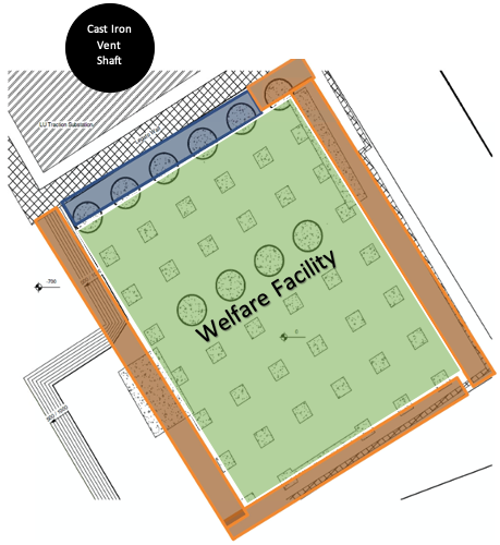
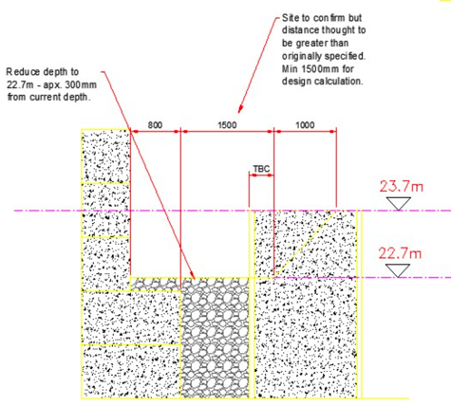
The platform needed lowering by about 1m over a 20m length to reduce the loading on the vent shaft – by removing 20m3 of 6F2 crush we would be able to reduce the loading on that area by about 48 tonnes. The sketch below shows the requirement to lower the platform from 23.700m to 22.700m.
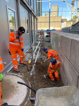
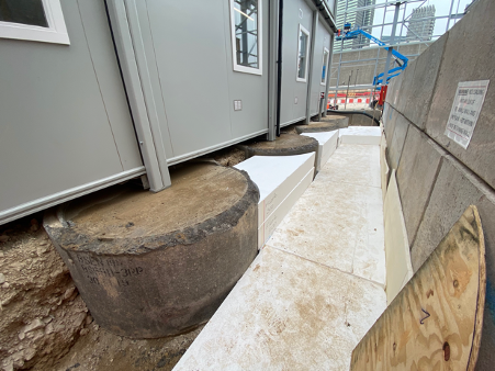
The photos below show the reduction of the welfare platform level.
Back to the footpath. I now had to install a footpath over a perimiter that over a 20m length had dropped by 1m. We considered 3 options:
- Build the platform back up to 23.700m with a scaffolding solution (not permanent enough and would be a burden for the weekly temp works checks).
- Drop the footpath down to 22.700m with either a concrete or Haki staircase (not DDA compliant and restricts maintenance to this north west side of the welfare facility).
- Build up the platform to 23.700m with a light weight material. (this is the option we selected).
The foreman mentioned that he’d seen polystyrene being used before as a lightweight filler and although no one else in my team had any experience with it, it was proposed as a solution to temporary works who signed off the design (see below).
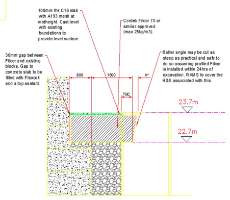
Filcor 70 is an expanded polystyrene with a density of 25kg/m3 and a compressive strength of 70kPa – plenty enough for us (although Filcor’s products go up to 190kPa, see link: https://cordek.com/products/filcor).
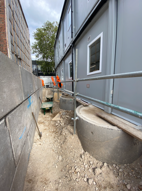
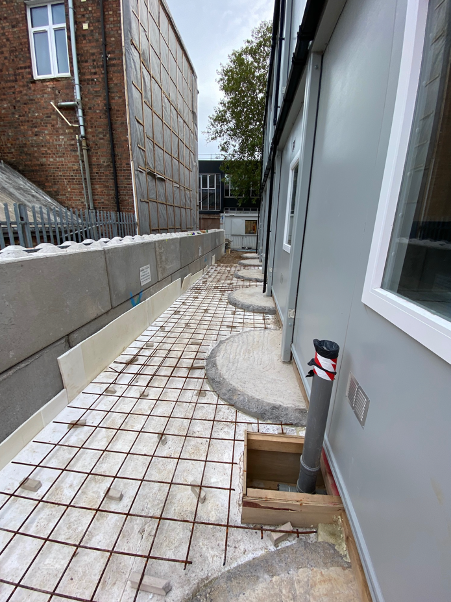
The photos below show the installation of the polystyrene followed by the concreting and finished footpath. I hadn’t heard of using polystyrene as a lightweight structural alternative so it might help people solve similar issues in the future – one to bear in mind.


Art of the Possible
I blogged a while back about the potential for dispensing with the need for generators by instead utilising the existing grid connected electrical infrastructure to power a winter environmental control solution for the ‘East Wing’ (Convective heaters and dehumidification units). The spare capacity in the infrastructure is due to the reduced footfall and activities on site a la COVID, with some quick analysis of the Building Management System data it was found that there would be sufficient capacity to provide most of the temporary heating electrical demand.
The cost of generators on hire and the fuel as well as the noise and the associated carbon footprint are undesirable given the cheaper and cleaner (carbon footprint per kWh, getting better and better) supply of elecricity from the grid.
Essentially the ‘East Wing’ has two zone distribution boards at the North and South end, both of these boards have 400 A three phase incoming supplies, therefore each distribution board can theoretically draw 276 kVa based on 400 A per phase loading with a phase to line voltage of 230 V. There are 6 floors to provide environmental control to with each floor having different loading requirements due to ‘high risk’ areas in terms of conservation etc.
We toyed with the idea of setting up a system whereby generators would be joined in parallel with the existing electrical infrastructure, the idea being you would maximise the grid capacity from the distribution boards and use generators to ‘top up’ any additional power requirements in the event of surplus demand. We were informed by contractors that to parallel generators up with the grid requires DNO (District Network Operator such as UKPN) permission, takes a long time and costs a fair amount of money (there is also no guarantee that the DNO will provide permission).
Therefore it was decided to match specific ‘high-use’ floors to the distribution boards which turned out to be the groundfloor, principal floor and second floor and the remaining floors would be supplied by dedicated generators. It has already been noted that the kVa demand of each floor has been based on no diversity i.e worst case scenario that all convective heaters and dehumidification units are turned on simultaneously. It has been confirmed that there are spare ways on the Medium Distribution Units to the three floors just mentioned which gives us flexibility if it becomes apparent that the diversity assumption is ‘overkill’ and we can extend the provision of grid power safely across more of the floors.
Also worth mentioning the ‘East Wing’ has been split into North and South zones for geographical convenience in terms of cabling and voltage drops from the zone distribution boards.
Potentially a blog post soon looking at the temperature and humidity levels in the building and the optimisation of the solution, just waiting on access to the environmental monitoring database (temperature and humidity sensors positioned across the floors).
