Archive
Green loans
3 min read. I came across this article and thought it may spark some interest…
The initial stage of Canberra’s light rail network today became the first Australian transport public-private partnership to execute a green loan.
Canberra Metro has partnered with the ACT Government to deliver award-winning, frequent, efficient and sustainable light rail services along the stage one alignment from Gungahlin to Civic.
Canberra Metro is delighted to announce that it refinanced the $280 million debt facility with a Green Loan with Climate Bond Initiative certification under the Low Carbon Transport Criteria.
This is a significant achievement for not only the project, but for the ACT Government, Canberra Metro and its owners (John Holland, Pacific Partnerships (a member of the CIMIC Group), Aberdeen Standard Investments and Mitsubishi Corporation). It recognises the significance of the first stage of light rail in its ongoing contribution to Canberra’s sustainability.
The project incorporated sustainability principles during design and construction and is now running on 100% renewable electricity and utilising environmentally friendly measures across its operation. The green loan has been issued in accordance with the Asia Pacific Loan Market Association’s green loan principles.
Categories that Canberra Metro qualified for the green loan under include renewable energy, energy efficiency, pollution prevention and control, clean transportation, sustainable water and wastewater management and environmentally sustainable management of living natural resources and land use.
In obtaining the Green Loan, Canberra Metro was assisted by our Financial Advisor and Green Structuring Advisor MUFG, our Green Loan Co-Ordinators, ANZ and CBA and our Mandated Lead Arranger banks ANZ, CBA, ING, Mizuho, NAB and SMBC.
A green loan is any type of loan instrument made available to eligible ‘green projects’. A green project may include renewable energy, energy efficiency, climate change adaptation and green buildings that meet regional, national or internationally recognised standards or certifications.
In the UK we are already familiar with loans or grants toward improved home insultation or installation of solar power. Green loans are also issued in Australia for private and commercial residential developments to boost construction of energy-efficient homes and help reduce household emissions. So whilst BREEAM sets the guidelines for assessing sustainable buildings, some banks have now started to create their own criteria. The goals of these initiatives are to build climate resilience within the banking system, as well as to raise authorised institutions’ awareness of climate risks and broader sustainability issues. In my opinion this could further drive the sustainability requirement from a client which in turn will be felt by the engineer. An interesting prospect for the future.
Conservation with Constraints
You have a heritage building with an inoperable Low Temperature Hot Water heating System due to reservicing works, how do you control the internal conditions such that you can be confident the building fabric is preserved, especially throughout the winter period?
Logically you would start by defining what ‘acceptable’ internal conditions are and then formulate a design. The key parameter for preserving the building fabric in a heritage building is ‘relative humidity’ which is predominantly a function of the absolute humidity and temperature. Relative humidity levels greater than 65% cause issues such as mould growth, insect attack and the expansion of hygroscopic materials (a material that readily absorbs moisture) due to the absorption of moisture. Alternatively relative humidity levels lower than 40% cause contractions in hygroscopic materials and ‘flaking or cracking’. It is a lot more complex than this especially when it comes to the conditions required for specific materials in museum archives (not required in this situation due to the widespread removal of valuable objects). Also worth noting is that RH and temperature fluctuations (not more than 10% RH and 4°C change in 24 hours) are undesirable.
For context, nearly all buildings cater to human thermal comfort requirements and typical setpoints of 21°C are specified all year round to ensure comfortable working conditions, the added benefit of this setpoint is the creation of a ‘humidity buffer’ i.e warmer air is able to hold more moisture before saturation and will therefore experience lower relative humidity levels than colder air for the same absolute moisture content. This means that throughout winter your 21°C setpoint will help prevent excessive RH. However, it is not always necessary to provide heat for human thermal comfort, the energy efficient method of ‘Conservation Heating’ (Using heating to control RH) can be used where human thermal comfort is not required and works on the principal that a 6°C temperature differential with external conditions will maintain acceptable RH levels. Essentially conservation heating is used in buildings that don’t require the energy intensive 21°C setpoint for human thermal comfort in order to save energy but still maintain acceptable RH levels.
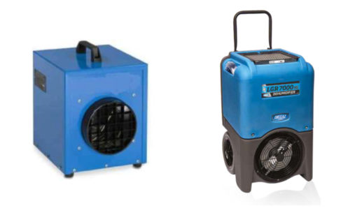
In more recent times, due to the increased emphasis on sustainability the use of dehumidifiers (relatively low energy demand) to control RH has been explored and succesfully employed in numerous buildings across Europe. Typically a dehumidifier requires low infiltration rates to be at its most effective.
The strategy for the building in question (The contractor is adamant about only using 110V electrical appliances to manage the fire risk) is to use a combination of heating and dehumidification units to control the internal parameters. The constraints in the title of the blog refer to the fact that the units can only be operated during the hours 0800-1700 during working days and that the need for asbestos enclosures require the temporary removal of the units from certain areas.
This solution is going to be in-situ for circa 6 months which equates to roughly 1000 hours of operational time. The way the units are used will have significant consequences for the energy consumption and cost of the design. For example, if you had 60 heating units drawing full power during the six month operational time slots you’re looking at a circa £25,000 electricity bill (based on 14.3 pence per kWh).
Ultimately both the units are controlling the RH of the room, the dehumidifier does this directly by reducing the absolute mositure content to achieve a RH setpoint whereas the heating unit achieves this indirectly by heating the room up to a pre-determined setpoint to reduce the RH. The dehumidifier has much better control as it will reduce the RH to the exact level you want whereas the heating setpoint (dictated by the user) will be constant throughout the day and is likely to be ill specified to realise the exact RH you want e.g you could find a situation where a 15°C setpoint reduces the room RH to lower than 40%.
It has been found that the entire building has high infiltration levels, the moment the units are switched off the absolute moisture content of the room equalises with external conditions (If dehumidifiers have been active) and RH increases and the heated room air quickly dissipates (if heating units have been active). Ultimately there is a complete lack of control outside of the operational window. The fan convection units are effective at heating the room air up and not the thermal mass of the building.
Initially a 10°C lower temperature limit for the building was set. Upon reviewing this limit it has been found that up to 400 national trust properties regularly flout this limit with temperatures as low as 6°C in order to maintain acceptable RH levels (Using conservation heating). Due to residual heat gains the building is only expected to drop as low as 8-9°C, coupled with the lack of human thermal comfort requirements and the reduced energy intensity of dehumidifiers the argument can be made that the convection heating units are unecessary.
It would be interesting to have trialled a range of different heating units such as oil filled radiators, radiative heating units and storage heaters to see how effective they could have been at heating the thermal mass of the building and maintaining out of hours control. It is my belief that fan convection units are poorly suited to the task of controlling RH levels in a heritage building and that the dehumidifiers should be the principal means of RH control as they achieve the same effect and with reduced energy consumption.
Effectively controlling the parameters 24/7 in light of the constraints specified in this blog is like entering a boxing match with both hands tied behind your back. Based on the data that is accumulating I envisage a compromise can be made between the constraints and the preservative requirements of the fabric.
“The Enemy That Kills You, Doesn’t Look Like You”
Read time: 5 minutes.
This morning was the ICE Strategy Session: Covid-19, Artificial Intelligence, and the future of the Civil Engineer. During the session, chaired by Rachel Skinner, Prof. Richard Susskind spoke about how AI and ‘the future’ might affect industries. His thoughts then provoked discussion amongst a board of construction industry experts.
Richard’s presentation focused on several key themes which I’ll summarise below:
The Mind Set
Richard explained that if, as an industry, we don’t want to be left behind, we need to change the way we approach problem solving. We shouldn’t be thinking about how we can do what we currently do faster, better or cheaper but change what we do all together to achieve the end goal.
An example Richard gave was the decline of the rail industry in the US. He suggested that their decline can be attributed to the rail industry’s inability to comprehend that they weren’t in the ‘rail business’, they were in the ‘transportation business’, and the customer didn’t care how they got there. Another example was given where the MD of Black & Decker explained to new employees that they weren’t in the ‘selling drills’ business, but in the hole making business, and if they find a better way to help customers make holes in walls that doesn’t involve a drill, then they need to adapt, quickly. The focus should be outcome above all else.
The Disrupter
The discussion then moved on to, “well ok, so who is it going to be that shakes things up”. After the CEO’s of several international construction firms (Balfour, WSP and others) discussed how we might adapt as civil engineers, Richard suggested that “the enemy that kills you, doesn’t look like you”. He went on to explain that whilst we might be able to disrupt and innovate internally, this is typically a very hard thing to do and usually it’s external people/companies who really disrupt industries.
So who might these disrupters be? Richard suggested that with the development of AI, data is king, and so it might be data analysts and scientists, not civil engineers, who create this disruption and lead innovation in construction. Mark Naysmith, CEO of WSP, supported this theory when he explained that as a consultancy, they’re employing more and more graduates with computer science degrees and even creative degrees such as art and music. Mark didn’t say if this meant he was consequently employing less engineers, I expect not, but perhaps this is us conceding as an industry that we, with all of our structural theory, might not be all of the solution to the problem. Those that don’t embrace this might be left behind.
Something that wasn’t mentioned in the strategy session, but I think reflects the sentiment, is what Dominic Cummings was trying to do in No. 10. We are familiar with the news that rather than employing civil servants and staff with politics degrees, he was employing data analysts and computer scientists to help run the government. Now, the success of his strategy would be a contentious debate, but to me the parallels are stark as we see an industry (politics) realising that the disrupter (the innovator) might not look like a politician.
My Opinion
It’s my opinion that the civil engineer, and what we design and build, will remain the solution to the outcomes required by society for at least the next 100 years. Whether that being transport infrastructure to enable trade and movement, energy infrastructure to power our homes or the high rise buildings to home us where space is a commodity. However, the longer we wait as an industry to ‘self-disrupt’ and innovate, the less control we’ll have over an industry that we regards as ‘ours’. This has already been witnessed with the modernisation of project management. The Bragg and many other reports of the 80s/90s that reviewed the technical and commercial practices of the civil engineer, saw the engineer’s remit transfer to project managers, quantity surveyors and schedulers. It’s my opinion that the longer we wait to self-disrupt, the higher the chances of what remit remains (such as risk management, construction sequencing, design and quality assurance) could become the remit of yet another specialist, perhaps data analysts and computer scientists.
Further Reading:
The session was recorded and should be available on the ICE’s website in a couple of days.
The board members were:
Prof. Richard Susskind OBE: A British author, speaker, and independent adviser to international professional firms and national governments, specifically on the use of AI.
Mark Neysmith: CEO of WSP UK and a member of the Global Leadership Team.
Simon Adam: Head of commercial for Crossrail 2.
Stephen Tarr: Managing Director of Balfour Beatty.
Suzannah Nichol: CEO of Build UK.
Chris Young: CEO of Tony Gee.
Preloading your backprops for maximum load distribution
Read time: 10 mins.
One of my first tasks on Phase 3 has been to develop a temporary works solution to support the demolition of the roof (RF1) and 3 levels (L01, L02 and L03) of suspended concrete slabs of the Coronet Theatre in Elephant and Castle. In order to demolish these elements, an 8 tonne excavator will be lifted onto L03 and break RF1; once completed the props on L02 will be removed and the plant will be lifted to L02 so that L03 can be demolished and so on.
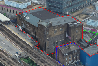

Specifically, I have designed a back propping system to transfer demolition loads (plant and demolition debris) from suspended concrete slabs to the ground. Back propping is required because a cursory check tells us that the concrete slabs were designed for imposed loads much lower than those imposed by an 8 tonne excavator and up to 0.5m of demolition debris.
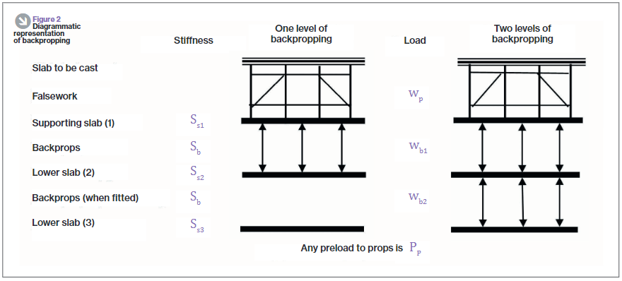
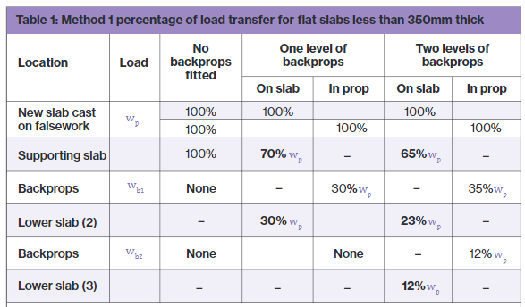
As you can see from the diagram, the loads from the working platform will be transferred directly to the ground, however, in the development of this solution I considered transferring the loads to L02 and L01 only to save the Client the use of the costly Titan props used on the ground floor. In doing this I used the principles taught to us in applied structures (by JAM I think?) that were summarised by Pallett (2016) typically used when designing falsework, see diagram below.
Pallett tells us that with two levels of back propping, I could distribute 65% of the demolition works loads onto L03, 23% to L02 and 12% to L01. With just one level of back-propping this distribution would be 70% to L03 and 30% to L02.
One might expect that with the use of a rigid prop, deflection in the top slab would equal deflection in the supporting slab as shown in the diagram below. If this was true then the load on the top slab would be split equally between the top and supported slab, 50% of the load to each. In essence, the two slabs become one member with the slabs acting as flanges and the props acting as webs. So why does Pallett tell us that the loads would be distributed 70/30, not 50/50?
The answer is because the props too act elastically and shorten when exerted to the axial load as required by d=PL/AE. If the member can’t shorten, then the load can’t be transferred. Instead, the interaction between the slabs and props looks much more like that in the diagram below. There it can be seen that the deflection for the top slab is greater than that of the supporting slab.
Preload your backprops!
Unfortunately it was still assessed that even 65% of the load imposed by the demolition works would be too great for the suspended slabs and so I looked for other solutions, determined not to use the expensive lower level Titan props. I had seen that Pallett released a further article in TheStructuralEngineer in 2017 that suggested that backprops could be pre-loaded, an interesting concept that I thought I’d look into.
Think about how you install a prop, typically you stand it between the supporting and supported slab and begin to twist the collar, extending the prop until it is firmly wedged in place. Well what would happen if you kept twisting the collar, perhaps using a sledge hammer or using a long spanner as a lever? The answer is that the top slab would start to hog and the bottom slab would begin to sag. It turns out that by doing this we can actually achieve the conditions so that the load can be shared equally between slabs, 50% each for a 2 slab system or 33% each to a 3 slab system as is the case with my problem in Elephant and Castle.
How to design back-propping
It’s all very well knowing that by exerting a load on the supporting and supported slab by preloading your backprops you can distribute loads imposed on the supported slab equally, but how can this be designed? It can be designed by the basic application of PL/AE.
Take the following example:
E: Prop material stiffness = 69 GPa. The Youngs modulus value for aluminum.
A: Prop section area of material = 0.00259m2. Taken from manufacturer’s technical literature.
L: Length of prop = 2.982m (distance between slabs).
P/d: The force per mm extension, kN/mm.
and rearrange the equation so that P/d = AE/L. We can then work out that for every 1mm the prop is extended, it exerts a force of 60kN. If we also know from the technical literature that one thread (turn) equates to an increase in prop length of 2mm, the instruction to site in order to exert 30kN to the supporting and supported slab each (60kN total), would be to give the collar half a turn. Tests carried out as part of the European Concrete Building Project (ECBP) found that by using this method with a prop system, you could practically apply an upwards UDL of 0.5kN/m2 on the bottom of a slab.
Of course, if using this method to equally distribute loads there are a few things that need checking:
- Has the supported slab got sufficient reinforcement to tolerate the hogging due to the applied upwards force; a typical concrete slab would have maximum sagging and minimal hogging reinforcement at mid-span.
- Are the loads acting on the supporting slab (self weight, load imposed by preloading props, shared load from supported slab, other imposed loads) within the capacity of the slab.
- As the axial force in your props increases so does the likelihood that they will buckle, they might need restraining with ledger frames.
The ECBP found that this method was difficult to implement with thin slabs because of their flexible nature leading to the tendency to transfer load between adjacent props as one is tightened up.
In all there’s nothing ground breaking here but a bit of applied engineering to distribute that little bit more load between your slabs, it might just make the difference.
References:
- Temporary Works Toolkit. Part 4: An introduction to backpropping flat slabs. Pallett, TheStructuralEngineer (2016)
- Temporary Works Toolkit. Part 6: Backpropping flat slabs. Pallett, TheStructuralEngineer (2017)
My biggest fan – 15min read
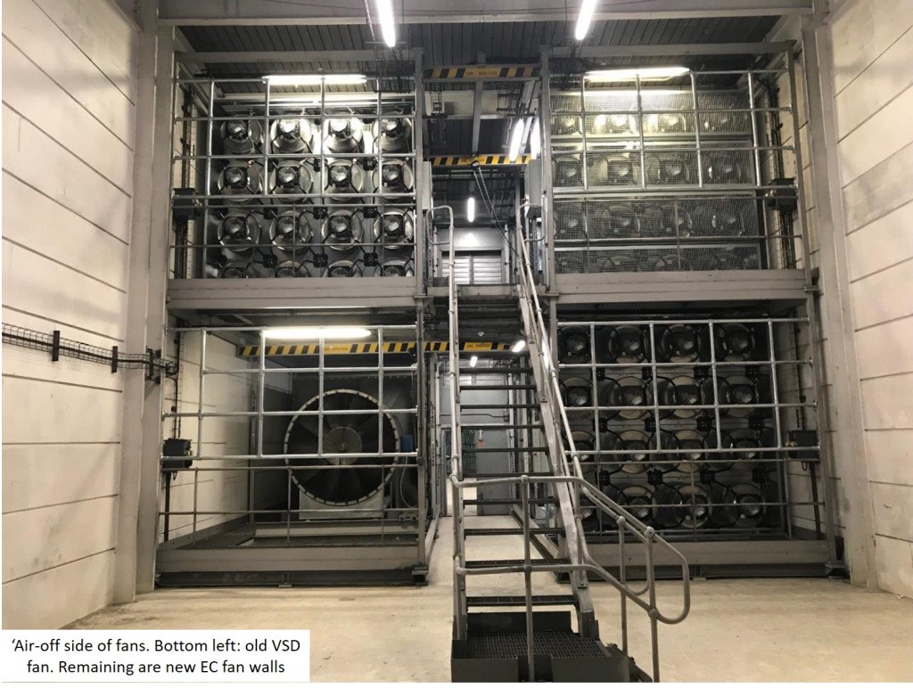
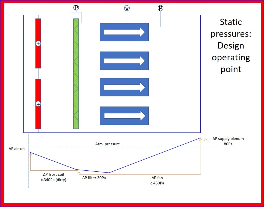
Part of the portfolio I have responsibility over as PM is the replacement of variable speed drive (VSD) motors with the retrofitting of electronically commutated (EC) fan-motor units (energy efficient motors, DC brushless motors by another name, sorry for the simplification John Marsh!). One of the sub projects is the removal of the original VSD fans from the three primary fresh air tunnels which provide fresh air to Terminal 5A. Essentially, there are three tunnels each with design flow rates of between 180 and 240 m3/s and a downstream plenum pressure set point of 80 Pa. These design conditions allow the AHUs within the terminal building to be able to ‘suck’ (I know pumps only ever push, Mark Hill!) fresh air into occupied spaces within the building. Each of the old VSD fans was replaced with a fan-wall composed of multiple EC fans.
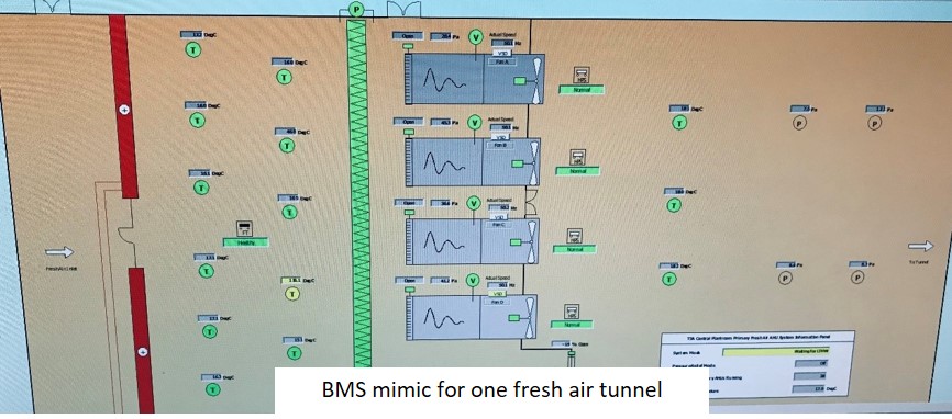
The project was completed in late 2019 and the static pressure in the plenum has never consistently reached the 80 Pa set point. There has been multiple inspections and heated conversations over who is to blame.
On the client side, Heathrow are clearly disgruntled at the increased energy demand of the fans, currently running at 100% (with no redundancy) and not meeting operating conditions. The operational engineering team within the terminal believe it to be a lack of capacity from the newly installed EC fans.
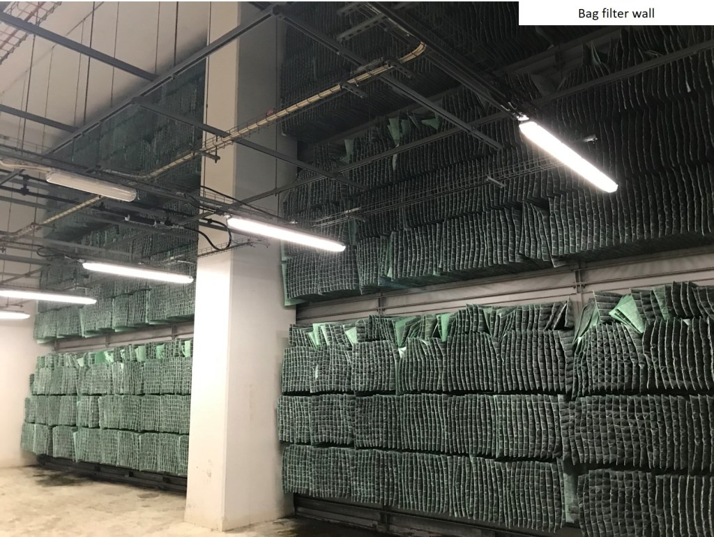
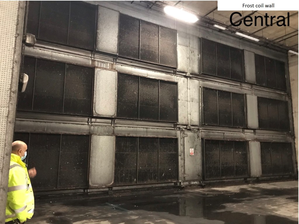
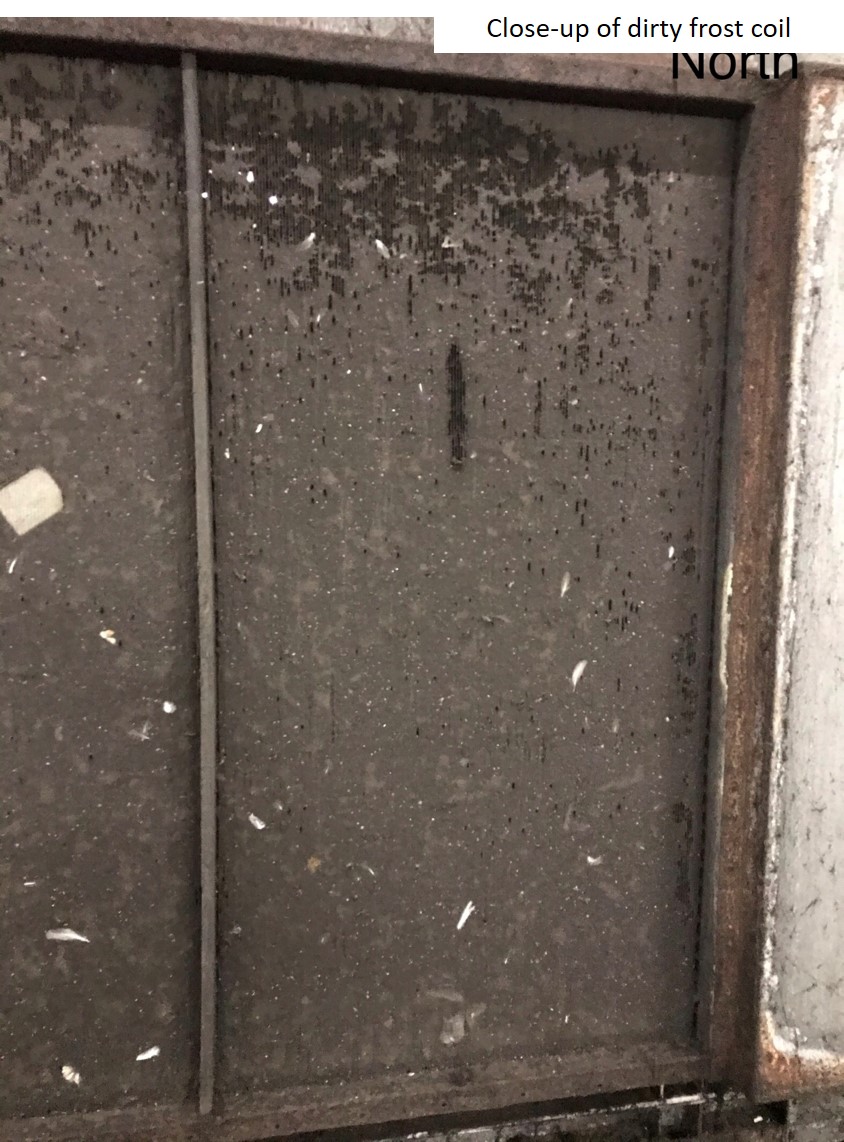
On the contractor side, they believe the fans are being ‘choked’ through poor cleaning and maintenance of the frost coil and bag filters that are the in the system and that the design is as specified by the original project scope.
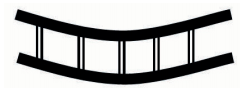
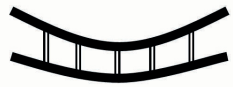
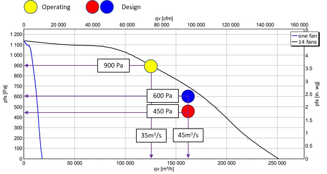
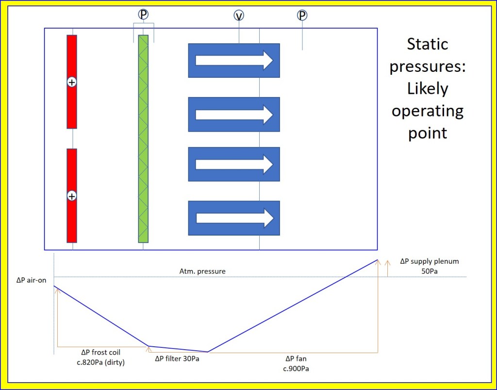
There had been a plan to install more pressure and temperature sensors within the tunnel but at this time there is no way to measure differential pressure across the frost coil or fans. The manufacturer of the EC fans published the fan-curve data as in the figure with the two operating points based on the original project scope that was handed to them in early 2019. Original commissioning information puts the maximum allowable differential pressure across the frost coil as 50 Pa and the bag filters at 225Pa. The frost coils are currently extremely dirty and gummed with incoming material entrained in fresh air. Although DP across the frost coils cannot be directly determined the bag filters are not running at anywhere near this upper limit.
The figures below show the likely operating conditions as is, along with the two cases published by the manufacturer, IF the EC fans are performing as per the published fan-curve.
Research into original commissioning information has revealed that there is a large difference between the maximum available duty of the VSD fans removed and the smaller EC fans retrofitted. Although this extra duty is not required in ‘normal’ operating conditions (ie. if the filters and coils remain clean and with low enough DP) in the past it could have easily allowed to overcome poor cleaning and maintenance of components by simply ‘turning it up to 11’.
Following some investigation I think there to be are a number of possible outcomes, in order of likelihood, following the correct cleaning of the frost coils an replacement of bag filters:
- The system will operate correctly and pressure set point is reached. Everybody goes home happy and electricity bills reduce.
- There still lacks the sufficient pressure in the fresh air plenum. This will then cast doubt upon the EC fan capacity and likely reveal that the original scope handed to the manufacturer did not allow for the total air flow capacity of the original VSD fans; no fault of the designer. Due to the size of the project this will likely be tolerated and downstream operation strategy of AHUs will have to change from working on pressure set points to perhaps CO2 levels.
- The EC fans are found to be lacking still and only through extra monitoring of running conditions of the fans (differential pressures and air volumes) the manufacturer is held to account.
Heat Pumps or Hydrogen?
Some are touting the Hydrogen Economy as the way forwards, while others claim Heat Pumps are the future. Thus far at Siemens, I have only seen evidence to support the former. Anyone seen anything from industry to lend weight to the argument either way?
Recent Sunday Times Article on a Hydrogen trial for clean energy.
Emily Gosden, Energy Editor | 432 words.
Hundreds of homes in Scotland will be the first in the world to have their heating and cooking needs met by pure hydrogen after a £28 million trial won funding from the energy regulator. About 300 properties in the Levenmouth area of Fife will have hydrogen-burning boilers and cookers installed without charge and will be connected to a new pipeline network supplying them with 100 per cent “green” hydrogen. The gas will be produced through electrolysis, which will use electricity from a wind turbine to split water into hydrogen and oxygen. The first homes are expected to be connected in 2022, with the trial initially running for four and a half years. It is being run by SGN, the gas network company, which has been awarded £18 million funding from Ofgem and £7 million from the Scottish government. Decarbonising Britain’s homes presents a significant challenge, with about 80 per cent of homes using natural gas boilers that emit carbon dioxide, which causes global warming. Hydrogen has been touted as a potential solution because it burns cleanly. Although boilers and cookers would need to be replaced, hydrogen boilers could be used in conjunction with existing central heating systems. Proponents say that this would be less disruptive than switching to all-electric heating systems, such as heat pumps. It also could enable the continued use of existing gas networks, which would be beneficial to companies such as SGN, which distributes gas to 5.9 million homes and businesses in Scotland and the south of England. Angus McIntosh, 42, director of energy futures for SGN, said that the trial was an “exciting opportunity to revolutionise the way millions of people heat their homes”. He said that the high costs for the demonstration project included the fact that the boilers and cookers were “essentially having to be handmade for the purposes”, but added that significant cost reduction was expected if hydrogen was adopted at an industrial scale. The hydrogen will be produced using an existing seven-megawatt wind turbine in Levenmouth and a storage facility will be constructed to hold enough hydrogen to supply the three hundred homes for five days with no wind generation. As a fallback, the electrolysis could be run using power from the national grid. Mr McIntosh said that the trial would be voluntary and would be “as safe or safer” as using natural gas. The hydrogen will have the same odour as natural gas and will burn with a coloured flame in the cooker. In the event of a leak, a safety device should detect it and cut off the hydrogen to prevent it “ever being able to accumulate to an explosive level”.
