Archive
Ex BRIDGE reshow
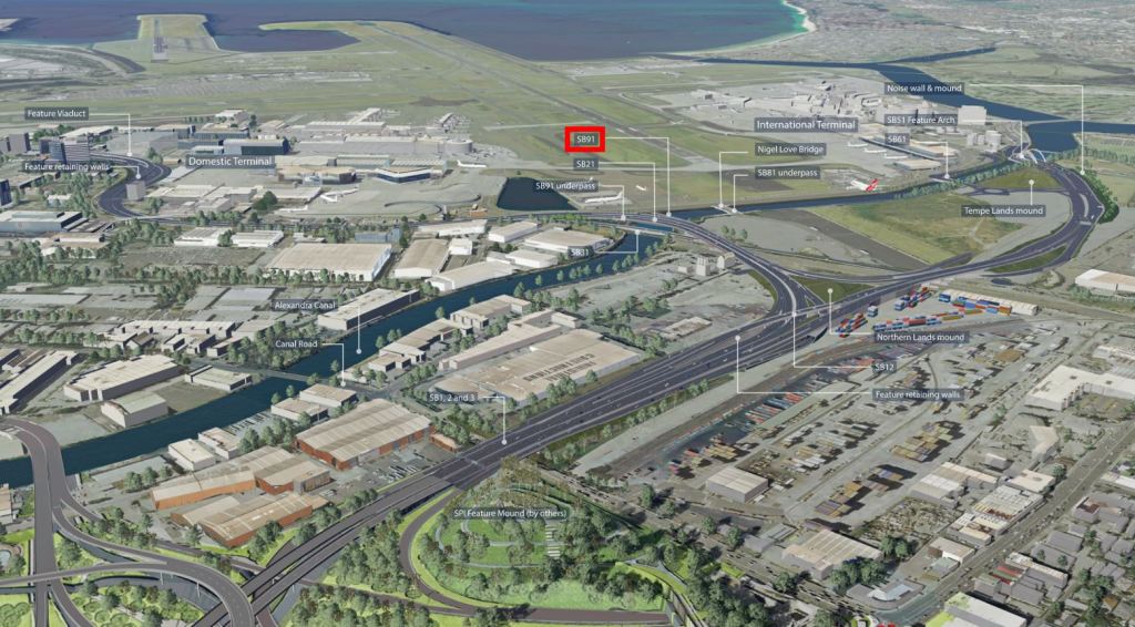
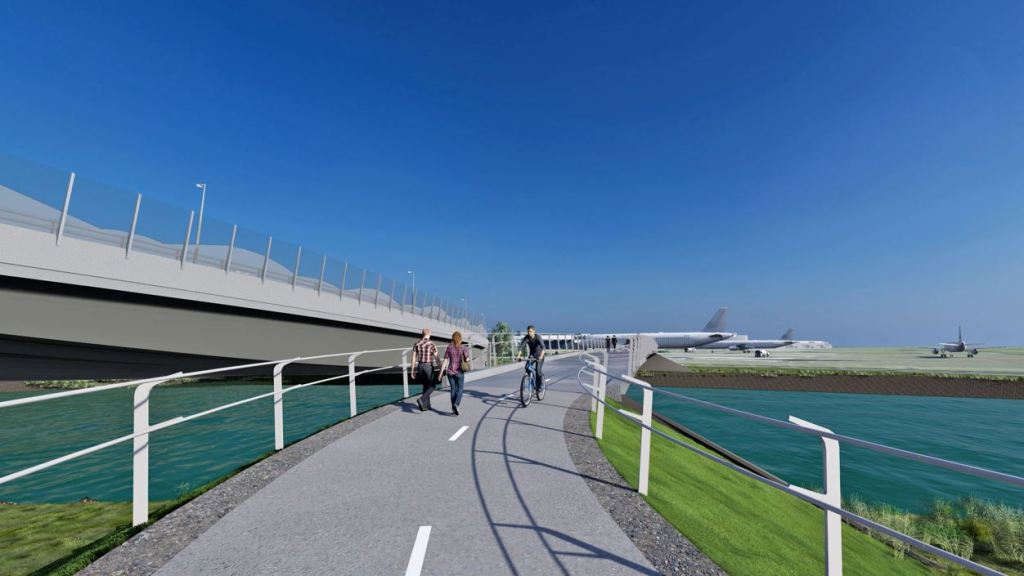
For my Phase 3 attachment I have moved to the Engineering Consultant BG&E and am working on a large road infrastructure project in Sydney. BG&E are designing the 13 bridges for the John Holland Seymour Whyte joint venture and I am leading on the pedestrian and cycle bridge over the canal to the north of the airport.
Spanning 75m it will be a steel concrete composite bridge with varying depth. The design interfaces with a few other design aspects and these have resulted in some very tight restrictions on the structure. Four key ones are:

Deck height
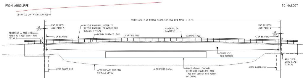
The deck is limited by the slope of the path from the underpass of the planned adjacent bridge to the centre of the bridge and the sight distance over the span. This slope is set to the maximum that is allowed by the disability act in Australia. This limits the max height at the centre of the span.
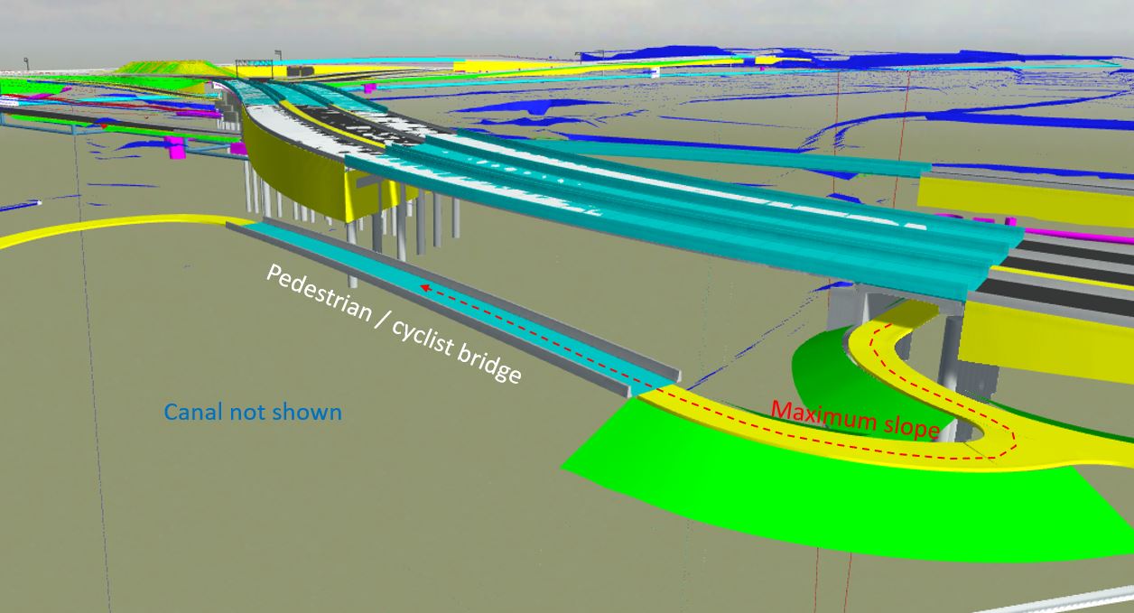
Bridge soffit
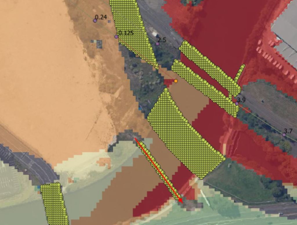
The underside of the bridge is limited by flood modelling. I assumed this would be set at 500 mm above the 1/100-year flood event as is stipulated in the contract. However, there is also a clause that the project cannot increase the predicted level of flooding at a substation 1.5km upstream during the Probable Maximum Flood (PMF).
The PMF is used to define the limit of flood prone land and has an annual exceedance probability of once in every 10,000 to 10,000,000 years. The issue is that the underside of one of the upstream bridges has already been set at the limit that causes an afflux at the substation, this means that the model is now very sensitive to reducing the height of my bridge.
The frustrating bit is that the substation will be flooded by 2 m during the PMF. The contract clause means this can’t increase to 2.01 m. I’m hoping sense prevails and this can be adjusted.

Alignment
This bridge was moved after tender submission and now the alignment is constrained by land ownership boundaries. When combined with the approach path radius it limits the angle at which the bridge crosses the canal. This pushes up the span to 75m.
Piers
Why no piers? This is because the canal is so heavily polluted form years of industrial use. Transport for New South Wales would rather pay for the bridges to span the canal, rather than deal with the risk of disturbing this pollution.
Impact
Because of all these factors the bridge has ended up with a span to depth ratio of 26 and about 130 tonnes of steel which has to be in one lift. My main concern is bridge dynamics as pedestrians are far more sensitive to bridge movements. Guess there could be a blog post in it…
Assessing Plant Loading on Concrete Slabs
For the last couple of weeks I’ve been working for a Client (Keltbray) who was awarded the work to re-purpose a 7-storey office building at St. Pauls, London. As part of the structure re-purpose, Keltbray are required to conduct a full soft-strip and a partial demolition of certain structural slabs, beams and walls.
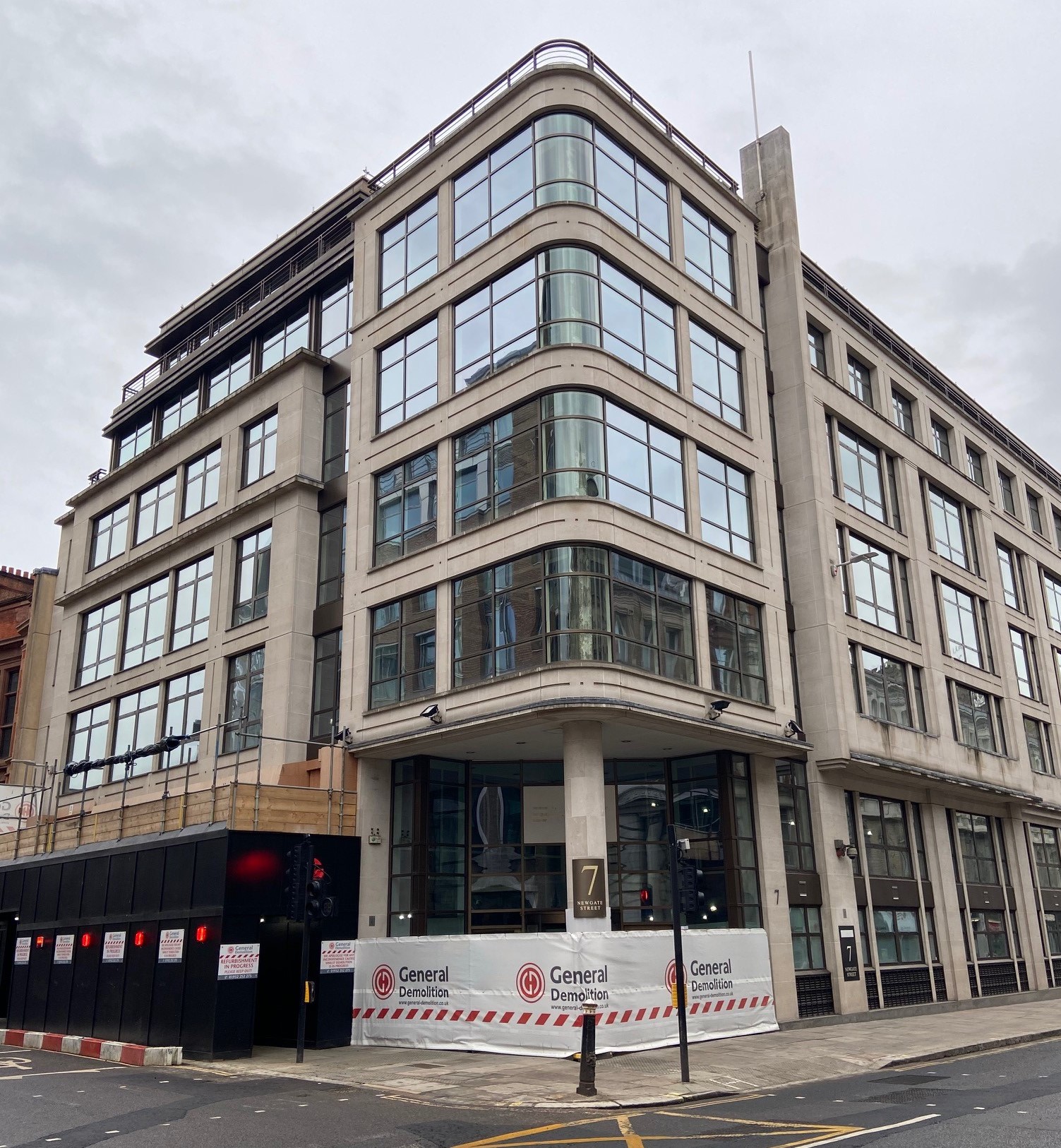
One of the design briefs issued to me was to confirm that the structural slabs on each floor had the capacity to support various plant including a Bobcat T450 compact track loader (see below). The T450 has an operating weight of 2,961kg, a track length of 1.28m and a track width of 0.3m.

In this post i’m going to summarise some of the quirks associated with plant loading and their load cases, and summarise some of the different methods I used to assess an in-situ slab.
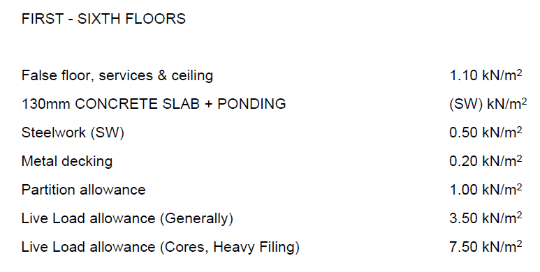
Check 1 – Structure Design Loads
Fortunately the Client was able to provide me with a demolition specification document which defined the working loads for which the structure was designed originally. If these are available, of course the simplest check to do is to see if the pressure exerted by the plant is less than the allowable loads as specified in the design load. In this instance I knew that after the soft-strip all false floors, services, ceilings, partitions and any other variable and quasi-permanent loads would have been removed. This consequently left me with 5.6kN/m2 slab capacity, unfortunately a very crude calculation showed that the load exerted by the plant would result in a pressure of nearly 40kN/m2.
Note – When using this method there is no requirement to factor the plant loads.
Check 2 – Check Max Bending and Shear
If check 1 fails, as it did for me, the next consideration should be that whilst the plant exerts a much greater pressure than the design loads, it is only exerted over a small area, compared to the design loading which could be exerted over the whole slab span. To do this I needed to consider the various loading combinations of the plant.
Step 1 – Establish loading configurations of plant
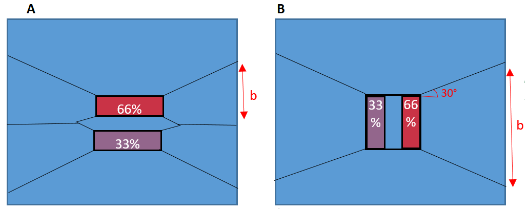
Tim Lohmann, Director at WHP, wrote an article in the ICE Forensic Engineering Journal explaining that the moments experienced by plant (through their typical construction activity) can cause an imbalance of loading. When these moments are perpendicular to the direction of the tracks, it can lead to up to 66% of the load being transferred through a single track. When the moments are in the same axis as the track direction, they can lead to a 33% reduction of effective track bearing area to due to the Meyerhof principles.
These principles are demonstrated in the figure below, for more information the article can be read by clicking ‘download’ below.
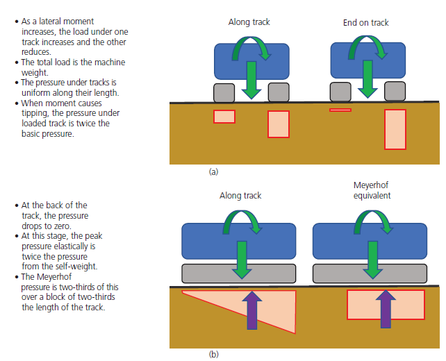
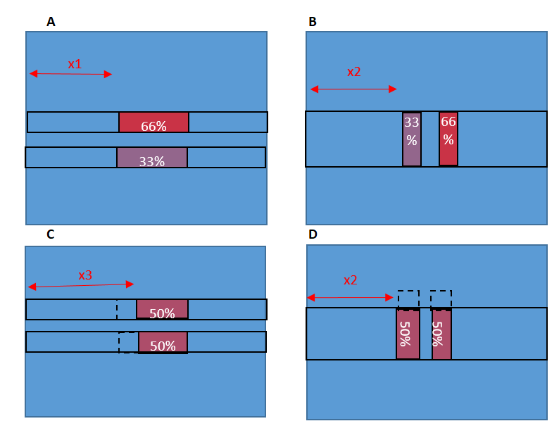
Because the slab I was assessing was one-way spanning, I had to consider both cases (a) and (b) above for the plant sat parallel and perpendicular to the slab direction. The four cases considered are in the diagram below. To find the max bending moment, the plant has been modelled at the mid span of the slab.
Step 2 – Calculate max SF and BM due to plant loading
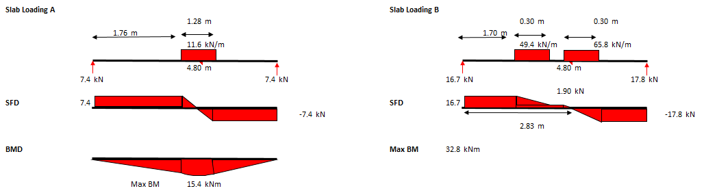
The maximum bending moment and shear should then be calculated for each of the 4 combinations shown above. The SFD and BMD for cases (A) and (B) above are below.
Note – Ensure that the span you select is the maximum slab span anywhere on the floor you are assessing, as this is where the maximum BM will develop.
Note – The loading due to the plant should still not be factored.
Step 3 – Calculate Max SF and BM due to slab design loading
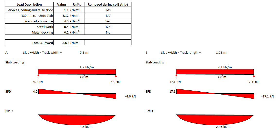
Using the design loads for the slab (5.6kN/m2 as determined from demo spec), the maximum SF and BM that the slab has been designed to withstand can be calculated. Below are the max SF and BM for cases (A) and (B) above. The 5.6kN/m2 pressure has been multiplied by the width of the one-way spanning slab being assessed which is a track width for case (A) and a track length for case (B).
When compared to the max BM due to the plant in step 2, you can see that the SF or BM due to the design loads is significantly less than the SF and BM developed by the plant loading. If, when checked, it is found that these BM and SF are greater than those developed due to the plant, the assessor could safely say that the slab does have capacity for the plant.
Check 3 – Slab Section Analysis
If check 2 failed then the checker should check the section properties of the slab for capacity against the max SF and BM developed in the slab due to the combination of plant loading, slab self-weight and any other loads that may not be removed during the soft strip. Whilst the plant is positioned at the mid-span, the max BM will be at the mid-span.
Note – For this check the loads should be factored.
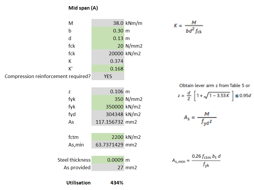
For my example, I calculated that for loading case (A) the max BM was 38kNm and then used EC2 to determine the steel reinforcement required. Because the slabs I was analysing were 130mm deep composite (steel deck) slabs, the 0.9mm thickness of the steel deck can be assumed to work as the tensile reinforcement.
Note – The yield stress of steel deck is unlikely to be the same as that for structural rebar (500N/mm2). I found it ranged between 280-350N/mm2 but check the manufacturer’s technical literature. The assessor should also check that the steel deck allows for sufficient bonding with the concrete for it to act compositely (normally achieved with dimples in the steel and shear studs).
A fundamental part of the check requires the slab (section) width to be considered. I noticed that when I considered load cases (A) and (C), where the slab width = track width = 0.3m, the section did not have sufficient bending resistance (failed by 334%) – see calculations below.
Check 4 – Assume load dissipates at 30 degrees
The assumption I had made from the very beginning was that, because the slab was one-way spanning, it was only the width of slab that was being loaded that could provide any resistance to bending/shear. However, according to BS8110-1, similarly to the way a concrete beam without shear links will normally fail on a plane inclined at an angle of about 30° to the horizontal, it can also be assumed that even a one-way spanning slab will utilise the strength of the surrounding slab, at an angle of 30 degrees.
Using the principle described above, a new b (slab width) can be determined which can be inputted into the same section analysis conducted in Check 3. For load case (A), I calculated that at the slab support, the slab width was now 1.72m. This new slab width allowed me to calculate that the slab did have sufficient tensile steel.

Note – The issue with utilising this 30 degree spread is that the same checks should be conducted with the plant moved from mid-span to close to the supports. As the plant is placed closer to the support, the max BM will reduce but so will the effective width of the slab (due to the 30 degree spread).
Additional checks required
- Whilst max bending occurs whilst the plant is at the mid-span, max SF occurs when the plant is closest to the slab support, this should be modelled to check shear capacity and punching shear.
- If check 4 (the 30 degree spread) is conducted, checks should be conducted for all 4 load combinations with both the plant at mid-span and close to the supports.
- If the slab is continuous, checks for tensile reinforcement in the top of the slab to deal with hogging should also be conducted.
Summary
When working for a design consultancy, the efficiency with which we carry out these kind of checks is what makes the company the most money. This post demonstrates a hierarchy of checks that can be used, from most basic to more complex until I reached the stage where my check passed. Whilst the labour intensive check 4 gives the highest chance of a check passing, a quick check might show that the simpler checks 1 or 2 might also pass (and take a fraction of the time to complete).
If even check 4 fails then FE analysis may be required. Otherwise it might be time to tell the contractor that they either need to downsize their plant, or back-prop their slabs.
