Archive
Drafting complex 3D structures – 2 min read
Building 3D models of bridges with complex geometries is beyond anything I can do in Revit. With varying curvatures in up to three dimensions it can take the bridge drafters a while to build the 3D models.
To do this the drafting team use a visual programming language which plugs in to 3D modelling software. To me the programming looks extremely complex but on a basic level appears pretty intuitive. Using this they are able to model the bridges. Importantly it allows different drafters (in separate countries) to quickly understand and update the models.
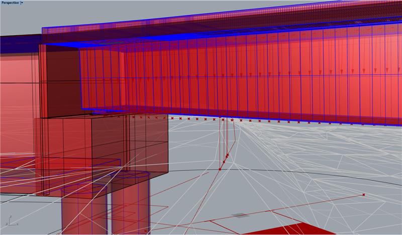
3D model of the bridge I have been working on. The soffit varies in a single dimension while the deck curvature varies in all three. 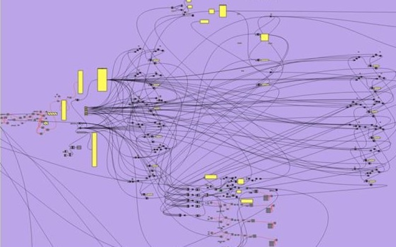
Screenshot of part of the visual programming language used by the drafting team to build a 3D model of the bridge. Software is Grasshopper. 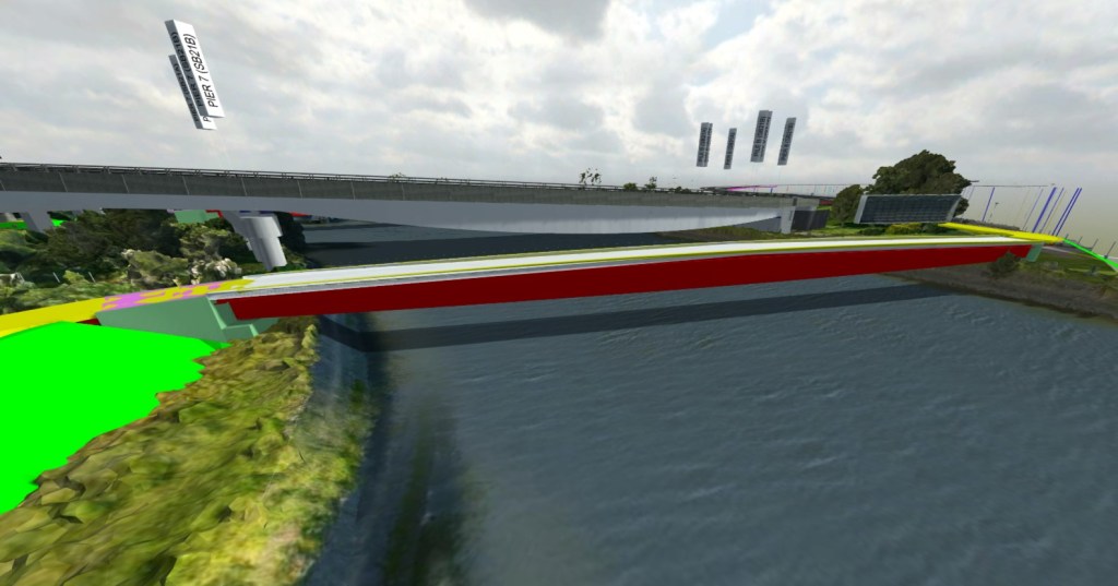
3D model imported into Revizto (BIM level 2)
The design consultant I have been attached to now exclusively use Revit on all building projects. However, the bridge team only use it on about half of the bridges with the other half being drafted in AutoCAD. Fundamentally though there isn’t much of a difference between the two. The Revit drafters use a DYNAMO visual programming language plugin while the AutoCAD drafters use Grasshopper 3D (visual programming language) and Rhino 3D (3D modelling software). With a lot of bridge drafting still done in 2D (cross bracing would take a long time to model in 3D) I can see why Revit has not been fully adopted. However, the bridge drafters believe that in 5-10 years they will be exclusively using Revit.
Train Spotting
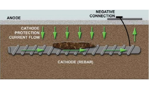
Now that I am officially into trains, or at least have been involved in metro, heavy rail and light rail projects, I wanted to write a quick blog about stray currents. Any current that leaks from the rails and conducts through any path, other than the dedicated return path, is known as stray traction current. As can be seen below stray current moves through the ground, ground water and potentially through surrounding structures.

Why this is important for civils, mech and elec? Corrosion. Whether you are designing and constructing the tunnels for the track to run through, station services and signalling, substations which power the rail and surrounding utilities protection against stray current will need to be factored into your design. Remember the school science experiment with a battery and beaker of electrolyte? Build a rail system and you have one big experiment, only now the corrosion will disintegrate your utilities pipe or the steel reinforcement in your concrete rather than the little piece of metal in the lab.

An electrolysis desktop study is used to identify the measures that should be taken to ensure stray traction current does not present a corrosion hazard to a proposed development. There are 4 key protection measures;
- The installation of heavy plastic membrane under (or behind) all reinforced concrete slabs, metallic platforms/gratings, piers/piles and metallic posts/bollards to electrically isolate from soil and the stray currents.
- Any steel reinforced piers/piles and metallic posts/bollards to be concrete grout encased.
- The use of plastic, rather than metallic, in-ground pipework where possible. In the event buried metallic pipework and/or cables are installed within the site, installation within sealed non-metallic conduit is recommended.
- The use of minimum 32MPa, high cover (min 50mm) concrete to limit moisture penetration to the embedded steel.
Infrastructure has a 100 year design life, beyond that of the measures listed above therefore cathodic protection is installed. Reinforcement bars are welded together to generate a loop through the structure. Generally two loops are created (redundancy) and tested for continuity prior to concrete being poured (site engineers ITP quality checks). An electrolysis point is installed at the surface of the concrete and a sacrificial anode can be attached.
Anyhow a little insight into stray currents and corrosion protection. I had never heard of this prior to arriving on site. Has anyone else had any experience?
