Construction methodology, critical for health and safety.
Earlier this month I found myself in the unenviable and quite unpopular position in the site office of stopping works on part of our scheme after raising health and safety concerns with the general foreman. Thankfully he could see my concerns once I explained the problem and we implemented remedial measures to rectify the issue; what was more concerning was the senior engineer on site could not appreciate the significance of the situation and the risks posed to the workforce. I have attempted to outline the engineering problem below, but in essence we had to extend a cofferdam which required changing the existing singularly propped solution to a cantilever solution. The construction methodology was critical to making these changes safely and I was presented with the scenario I discuss after taking a few days leave and had to raise my concerns when I returned to site.
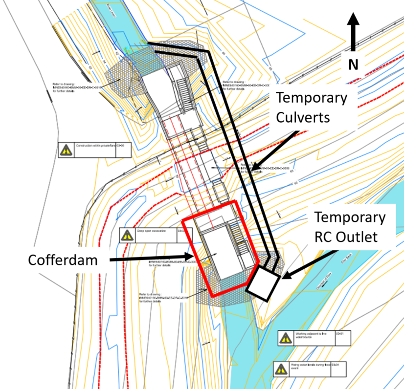
For my Phase 2 attachment I have been working on the Stokesley Flood Alleviation Scheme (FAS) with the Environment Agency acting as the Client. The scheme is split over several sites spanning 5km linearly along the River Leven flowing through Stokesley, a flood diversion channel and Eller Beck and makes extensive use of various temporary works. The package of works I write about here is known on site as the ‘Downstream’ works and consists of a reinforced concrete flow control structure constructed in the bed of the River Leven (flowing north to south) at the confluence with Eller Beck (flowing north east to south west); schematic shown in image 1. When I arrived on site in March the inlet structure to the north and 3 of 6 pre-cast box culvert sections had been constructed. The construction of a cofferdam, outlined in red, was required to complete the outlet structure and remaining culvert sections.
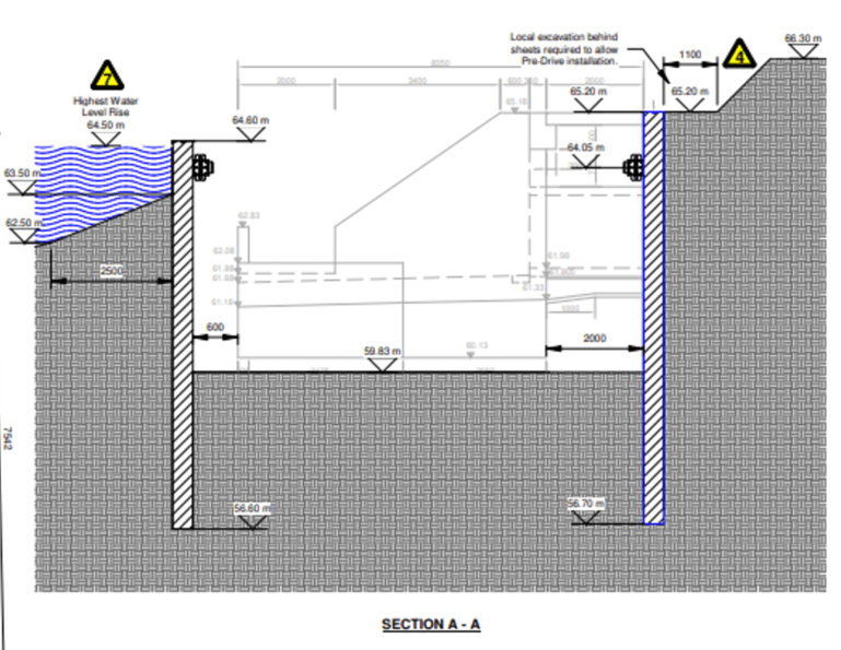
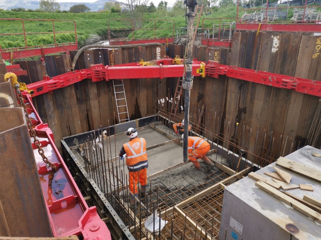
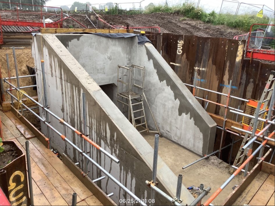
The original temporary works design (TWD) was provided by the specialist temporary works contractor MGF, images 2 and 3; this consisted of a combination of 8.5m (blue in plan view) and 8.0m (black in plan view) GU16N sheet piles. Image 4 shows the original cofferdam design on site during the concrete pour of the outlet structure apron apron. The worst case lateral pressure has a top of pile (TOP) at 65.20m AOD, prop at 64.05m AOD, dredge level at 59.83m AOD and toe depth at 56.70 m AOD (although actually at 56.20m AOD as 9.0m piles were delivered); therefore a singularly propped solution with a retained height of 5.37m and embedment depth of 3.63m. The lateral pressure on the southern face was modelled with a reasonable worst case flood level of 64.50m AOD and a TOP of 64.60m AOD specified (why a uniform solution with one pile length was not provided is a separate discussion).

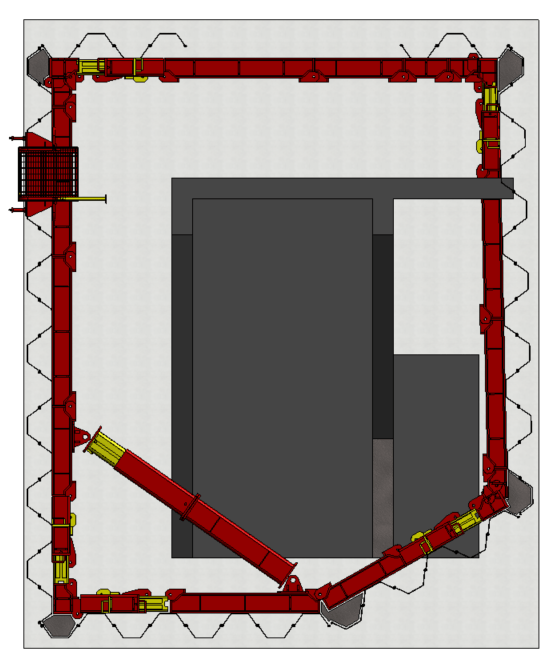
Due to the placement of the temporary outlet structure for the temporary twin culverts, image 1, which was necessary for bypassing the flow of the River Leven, the south eastern face of the cofferdam was constructed at an angle to prevent clashing with the structure. The issue this presents is the south eastern face of the cofferdam now clashes with the mass pour concrete base for the access stairway, an issue that could have been prevented with early planning and 3D modelling but is not expanded upon here. Image 5 shows a plan view of my Revit model which presents the clash clearer. Therefore, an additional engineering solution was required to complete the works for the access stairway once the outlet structure was completed, this drove a TWD change request which I submitted along with a potential solution. A schematic showing the required changes is presented at image 6; remove half of the temporary concrete outlet and realign one of the temporary culverts (if this was completed in the first instance then we could have avoided the change entirely), the sheet piles indicated by the orange lines had to be removed so as not to clash with the concrete base and further sheet piles installed along the red lines to retain the eastern side of the excavation and the river to the south.
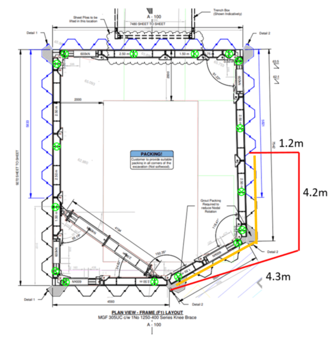
My proposal was to engineer a solution that would make the bracing frame redundant and allow the sheets piles to work in cantilever, noting the constraints of the length of pile and existing toe depth, then remove the frame prior to extracting the required piles. The proposed sheet piles could then be installed, again acting in cantilever, to provide the space required to complete the works. I perceived this as the most workable solution given the requirement and conducted a rapid assessment on Geo5 before sending the proposal to MGF. In short, the proposal was as follows;
- Backfill around the north and west of the outlet structure with 6N and compact to SHW 600 to a level that enabled the existing piles on those walls to work in cantilever.
- Excavate the active side of the eastern wall to a level that would again allow this wall to act in cantilever as the original dredge depth was required for the access stairway base.
- Model the river level as 63.30m AOD along the southern and south eastern walls (62.00m AOD has been typical for this time of year) and ensure the initial works are completed within one day when the river level is below this level. Again, this allows the walls to act in cantilever.
- Remove the bracing frame.
- Remove the piles specified (floods our works but is unavoidable).
- Either, install longer pile sections to act in cantilever to retain the original TOP level (MGF would need to specify) or install the existing piles along the new alignment to a new TOP level of 63.30m AOD.
Noting we would have to take risk that our works will flood at a reduced river level, the Sub-agent on site went with the later solution due to the additional time and cost of the first. I stressed to the site engineers that if this solution is approved the works must be completed within one day, in the specified sequence and when river levels are particularly low as we cannot take the risk on an overnight flood event above 63.30m AOD with the current TOP level and no bracing frame. Whilst I took leave Thurs to Mon that weekend, a TWD was provided by MGF with supporting calculations on the Thurs and this was approved by our TWD team on the Fri (BS 5975 specifies the level of checks required for different types of temporary works). Within the solution provided was the MGF construction methodology for carrying out the works which was the same as I outline above.
On the Tues I returned to site expecting to discuss the TWD, order the required piling rig and write the RAMS; unbeknown to me, on the Fri a temporary scaffold had been constructed inside the cofferdam and the frame removed, image 6. When I inspected the works, north and west of the outlet structure had been backfilled to the required level but the eastern and southern walls were still at the original TOP level and the active side of the eastern wall had not been excavated at all. We now had a situation whereby the retained height on the eastern wall was still 5.37m and the embedment depth was 3.63m (furthest wall in image 7) whilst the TWD solution specified a retained height 3.30m and embedment depth of 5.70m. The southern wall was still at the TOP level designed for a flood level of 64.50m AOD but was now only designed for a river level of 63.30m AOD.
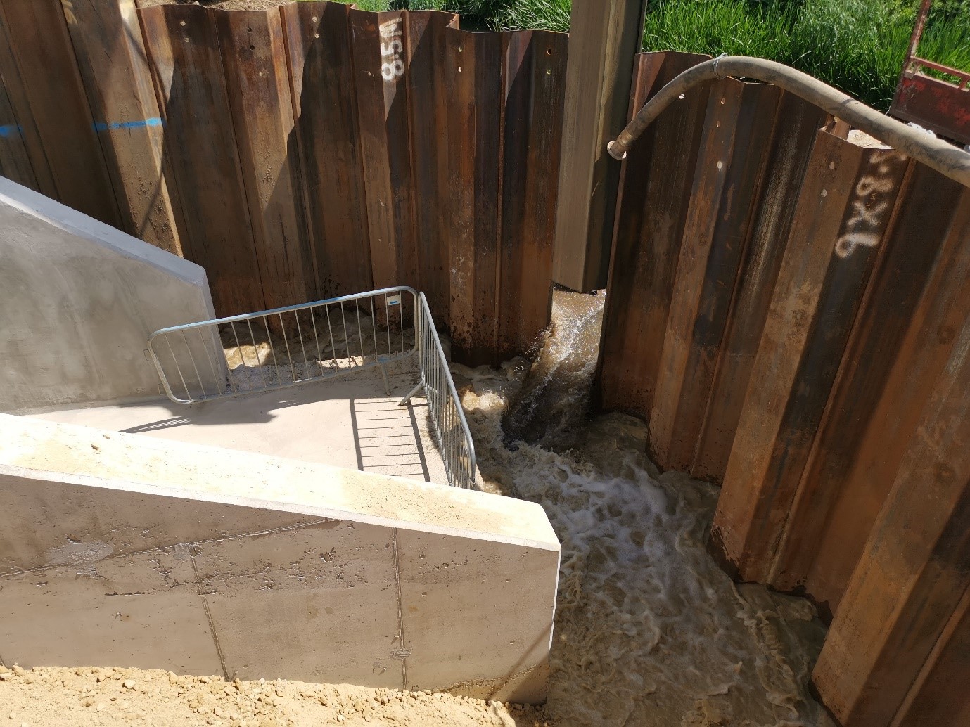
My first action was to clear the cofferdam of any members of the workforce and explain the risks we now faced to the site team; to my dismay one of the other engineers on site said it had been like that since Fri and so must be safe and we could excavate the eastern side whilst realigning the piles. Once I explained the MGF solution and construction methodology to the foreman we considered what remedial actions we could implement to rectify the situation. Obviously we could not put anyone back inside the cofferdam to reinstall the frame and we could not surcharge the eastern wall to drive the piles to the required level. We elected to pull one of the piles on the southern wall from the stable western side (image 8) and flood the cofferdam to minimise the risks of flood levels rising and increase the lateral pressure on the passive side slightly. We then positioned a 30t excavator at maximum reach from the eastern wall to excavate the active side until at the required level for the TWD; we were content that at this reach the excavator operator was at minimal risk from the wall failing due to the failure plane of the active earth pressure. Once safe, we then completed the remaining works in accordance with the TWD.
I wonder if anyone else has been exposed to a situation where a construction methodology has not been followed which has led to health and safety risks or where another engineer has not understood the overall engineering of temporary works which has increased the risks to the workforce. The concerning thing about this scenario is that work would have continued inside the cofferdam had I not been on site that day and the workforce were unknowingly put at risk when removing the frame four days prior.

Mat, great read. It sounds like things could have turned out very differently had you not been there to highlight and resolve the situation. I’ve not come across any such imminent safety issues so far on site but I often see attempts at corner-cutting which are potentially dangerous.
One recurrent challenge I come across on site is that of over-enthusiastic excavator drivers. On my site each “lift” of shaft construction involves bulk excavation, trimming to profile and spraying concrete in multiple layers to support the excavation. Our daily works permit (known as “RESS” – Required Excavation and Support Sheet) outlines the allowable excavation and support method.
One specific piece of information given here is the depth of bulk excavation for the start of each lift. Naturally our miners are keen to make good progress and are prone to excavating too far citing “it’s all going to come out eventually” as a good enough reason to go beyond the imposed limit. As with the rest of the engineering team I am quick to enforce the need to stick to the given depths but I am unconvinced of how well the need is understood across the team.
As should be clear, in going beyond the allowable depth, the miners could start pushing the boundaries of the GEO (excavation stability) and HYD (piping and base heave) risks that the RESS is designed to manage. I am intending to delve deeper into how the excavation limits are chosen as they use very round numbers but what I don’t know is how drastically they have been rounded. The convenient numbers make works easier to manage but we may be working inefficiently by limiting the depth of each lift and not utilizing the full capacity for the ground (in this case London Clay) to self-support between excavation and spraying. A potential topic for a future post!
Max, thanks for your comment, I would be interested to read your case study once complete. We have the same issues with some of our excavator operators when dealing with deep excavations. and dare I say it with the other engineers as well.
A couple of things that made me feel more uncomfortable about the above situation is MGF do not design embedded retaining walls to EC7, they use an old BSC Piling Handbook (6th Edition) which I am trying to get a copy of (if anyone has a copy I could have that would be great). Using this method they do not include an over-dig in their calculations and they do not use partial factors for on soil parameters; they just use a FOS of 2.0 on the moments to get the embedment depth. As such, the EC7 checks I conducted using Geo5 give a more onerous design than the piling handbook (by 0.5m pile length); I wonder if the EC7 design is overly cautious and will compare the two if I can get a copy of handbook.
I will post a case study comparing the two approaches in a future post.
An interesting piece
I am of the opinion that an obvious route to better engineering is to build in the virtual space. I am increasingly depressed because, whereas the methods are deployed at the high end
a) they outcomes seem to be choked off somewhere in middle management so that little is seen at site level
b) ‘ordinary’ engineers are not coming through with the skills to eradicate many of the problems before the build starts – it is still seen as something ‘high-end’. But it shouldn’t be
It is not unusual for there to be a very poor understanding – almost dismissiveness of -engineering principles at site level. It has never been different.
This and poor design leads to the situation in which application of principles in a bad situation are seen as ‘adding cost’ whereas the same principles applied in a timely fashion do the opposite
As to the particular solution here: flooding adds balance pressure to the passive side but increases the pore pressure in the soil in that side, decreasing the effective strength – careful!
I might have looked at trying to dig a chevron wall on the active to locally drop the active side pwp before reducing the active side surcharge . However it sounds like excavation on the active side was difficult