M25 Junction 10/ A3 Wisley Interchange Upgrade Project
I have recently started phase 2 of the PET course working as part of the earthworks team in Balfour Beatty who are delivering the M25 J10/A3 Wisley interchange upgrade. The project includes the widening of the A3, free flowing left hand turns at every corner, the widening of the existing interchange roundabout, an 8 mile long non-motorised user road and 8 new bridges. There is also an increase in the road furniture and a number of re-wilding projects to offset the impact of the removal of green space along the M25 and A3. A brief overview of the project is below.
Client: National Highways (formerly Highways England)
Contractor: JV between Balfour Beatty and Atkins
Budget: £317 million
Project Start: Summer 2022
Estimated Finish: Summer 2025
Website: M25 junction 10 – National Highways
The earthworks team is responsible for cut/fill, sub-base and temporary working platforms across the whole project. The cut/fill is occurring around sheet piling operations to remove excess material, after existing bridges have been demolished and back filling behind new bridge abutments. The temporary working platforms are used primarily for sheet piling operations, CFA installation and self-propelled modular transport (SPMT) bridge construction. The construction of the platforms to enable these operations is my primary focus at the moment. Some of the temporary working platforms will be used for enabling horizontal drilling operations for services, something that will become a blog post in the near future. Below is a selection of photos of my time on site so far:
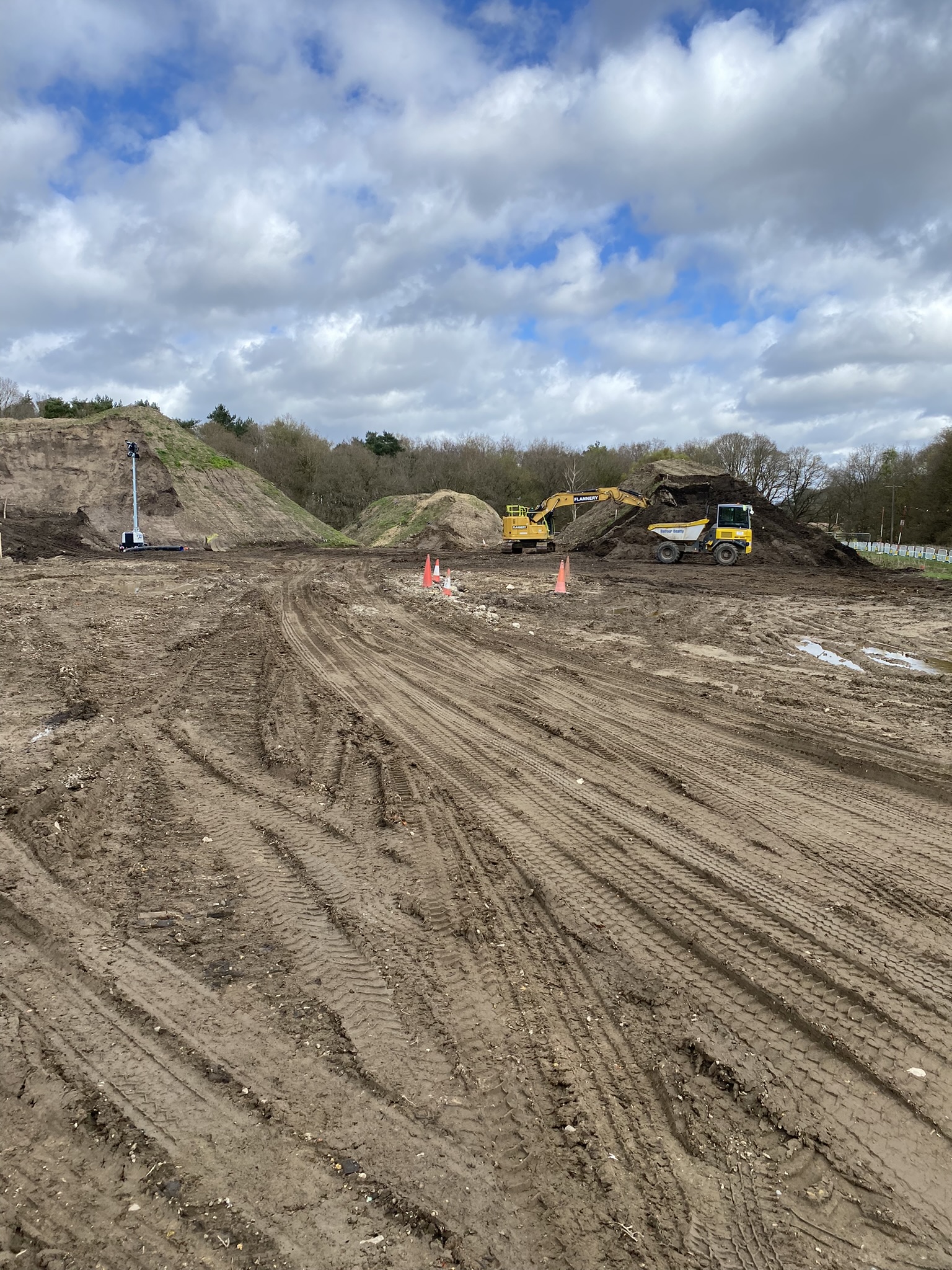

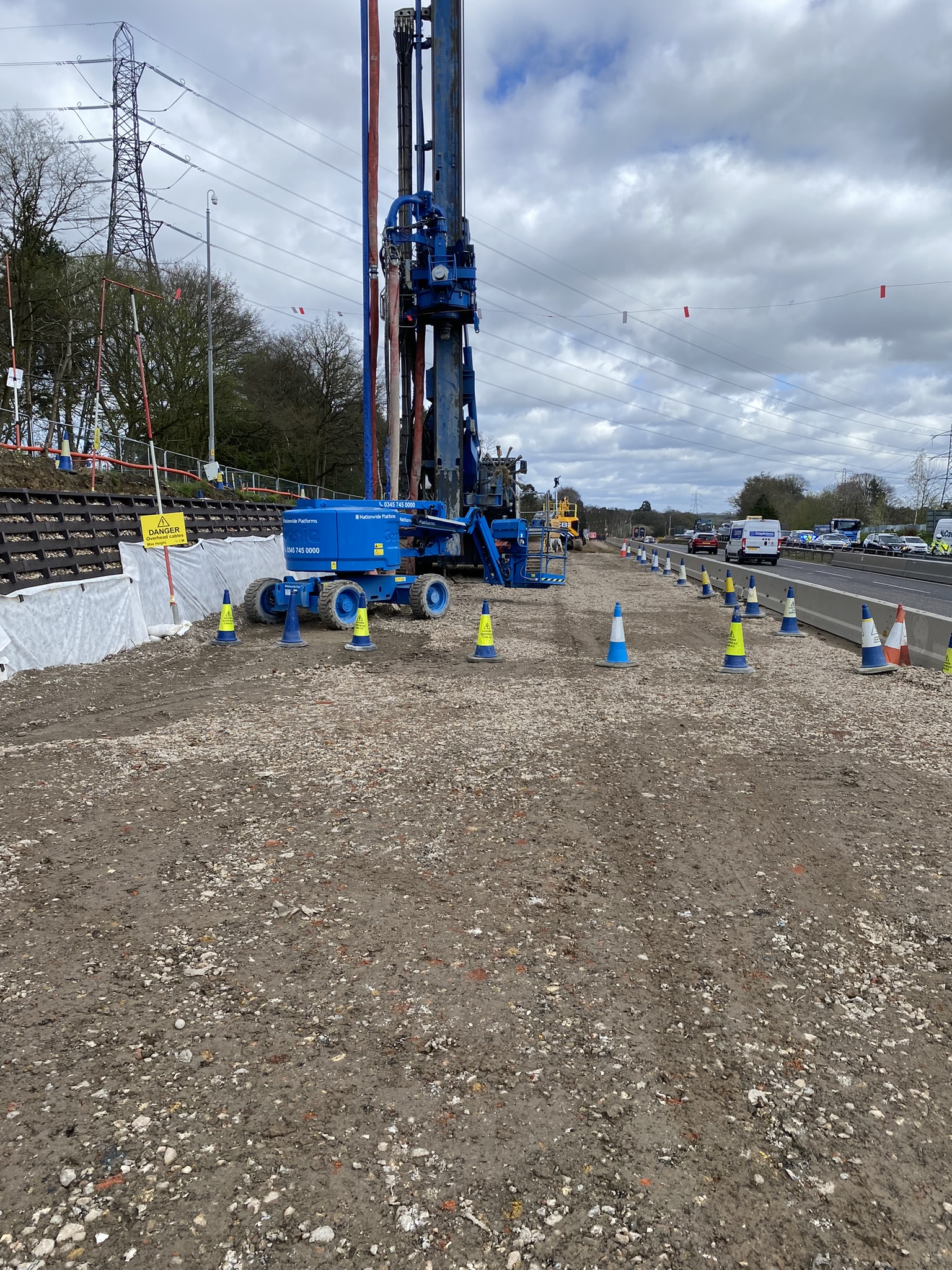
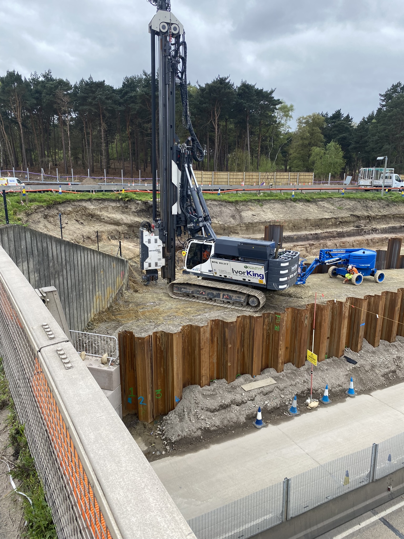
Note: all the photos are from different areas of site but demonstrate the amount and variety of temporary working platforms that are being installed. The sheet piling operations are all temporary works and are being conducted just to install some piled foundations for a bridge abutment. All of that work will be taken out once they have been installed.
A number of challenges have already become apparent on site. As often seems to be the case, there is a disconnect between the designers (who are not geographically co-located with the site team) and the reality on the ground. Some temporary working platforms have co-ordinates that place them in the middle of live traffic which is clearly not a workable solution. Others have half of the platform at the road level and the other half 5 or 6m higher with no scope to batter or step the slope due to site boundaries. When this occurs, a significant amount of time is then spent trying to establish what the designer is trying to achieve and how the platform is going to be used. This involves engagement with designers and sub-contractors so that we can construct something fit for purpose and in the right location.
I’m looking forward to getting more involved in the project; there is a lot going on and I hope to get involved with as much as I can. If you have any questions or would like to know more, please don’t hesitate to get in touch.

Joe,
Fantastic, a great intro blog and first (unless I’m mistaken) of the phase 2’s to blog!!
Not sure why but pictures haven’t come through for me (maybe my phone, anyway)
Can you offer any reasons as to why the initial designs have significant errors? Human error? version control? lack of recce (time spent on, and all that!) what’s the ‘so what’, probably in terms of time and cost (and quality?) Who owned this risk that has now become an issue?
I think the errors are primarily location based and seem to be a break down in communication between the TW designers and the co-ordinates on the ground. But there is also a part of me that feels it may be a little bit of laziness; most of the platforms are similar dimensions and size (because the work being done on them is the same) and it feels like the designers have drawn a rectangle on CAD and put it roughly in the location that they think it needs to be on site. However, some of the working areas along the side of the highways are really narrow and can only facilitate a 7 or 8m wide platform, compared with the 25m that they ask for. The other frustrating thing is that when you ask “can we do a 7m platform”, the answer is almost always yes, which begs the question, why can’t it be 7m wide initially? It’s a 1/3 of the material requirement, 1/3 of workforce time and could be significantly more efficient. I’m reticent to lay the blame at the designers door because I’m sure they are working on significantly more complex issues but for me, this could be more efficient.
I’m yet to establish how risk is managed in this team/on this project, probably due to my lowly position but it doesn’t seem to be well managed at all. In the self delivery team, they focus on value rather than cost, something that I need to spend some more time understanding, but as far as I am aware, there are no penalties for missing deadlines so the issue seems to be passed around different teams, get resolved with no issue or even early warning raised. To demonstrate this further, we went to look at the next platform that I’ll be working on yesterday. It is due to start in just over a week and they will have 10 working days to complete the works in time for the piling contractor to come in. I said that there is no way that it is going to be done in 10 days and we should either look at nights or weekends and the response was ‘No, it takes as long as it takes’. This attitude will have knock on effects elsewhere on the project and I’m interested to see how we manage to drive efficiency with a ‘it takes as long as it takes’ mentality.
Thanks Joe. I have the photos and I am pleased to say that when I asked my wife if she recognised it, expecting a response of “is that Wisley?” at best the rply was “its a piliing rig on the side of the M25”. I have obviously pointed out one too many rigs!
I know the site is on the edge of the Surrey heath and self drains being pretty much a well graded yellow SAND. I have also noticed significant errosion of excavations left open as I have driven past. The questions that flow are thefore how comfortable are you with the stock pile side slopes and is there an issue with protecting the subgrade?
I echo Mikes remarks regarding co-ordination. I am pretty sure I have seen fully rendered models of the completed works so I would expect there to be a syndicated model. What level of BIM is this project working to and how on earth can there be discrepancies at this stage?
Glad it uploaded, I spent hours trying to sort permissions and troubleshooting!
I remember you mentioning this in class and I was going to send you a short case study but since you have asked again, here is what I understand. Firstly, I was surprised to see some of the slopes of the stockpiles at the gradient that they are at. I’ve mentioned it to a few of the site workers and they are comfortable with them, but they seem steep to me. There are some locations that you may have noticed where there is geogrid exposed on quite steep banks. The plan for these areas is to cut it back, sheet pile and then back fill behind it, but it does mean that there are slopes that appear steep and potentially unsafe along some areas of the M25. When I have asked, the answer has been that they will be made safe once the work has been completed.
In terms of protecting the sub-grade, they do have quite a robust procedure. Every formation level is tested using a lightweight deflectometer test (LWD) and it must achieve 50kPa before any MOT Type 1 is laid. If it doesn’t achieve this, then more excavation is required and a capping layer is installed, but this hasn’t occurred in my time on site yet. The laboratory team who do the testing are very strict and will not test in wet conditions and insist that any test on the sub-grade is covered almost immediately with MOT Type 1 to prevent any degradation of the material.
The project is using a programme called Navis Works which has a fully rendered 3D model as you have suggested. However, it does not appear to be well sequenced and is used primarily for the finished elements of the project. This means that the enabling works that I am currently working on do not appear on the model and probably go someway to explaining some of the discrepancies. I have posted a reply to Mike’s message as well which may give a bit more detail.
Thanks Joe, Navis Works is used quite extensively for 4D BIM, particulalry in the demoistion sector to show the works progression and avoid issues throughout the job. The “done when it’s done” attitude doesn’t fit with sustainble construction or modern practices!
If you haven’t met Sam Bowers (BB) hunt him down and have a chat as he passionate about the ecological and environmental aspects of this project and is also very pragmatic in his approach. He’s not typical of the breed unfortunately but his take on ecology is refreshing and very interesting.