Glued Insulated Joints and Why Not to Use Metal Measuring Tapes
One for the E&Ms but explained in Civil speak! Many Australian trains are electric, particularly in urban areas. These are powered by overhead cables and a pantograph system. Electricity is provided to the train as 1500V, DC power and is converted through a rectifier and inverter to three-phase AC power to power the motors. The circuit is completed through the train wheels touching the steel rails which act as a return conductor to the nearest transformer.
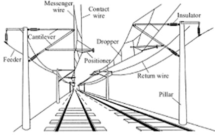
Additionally, there is a second current in the tracks, at a different frequency and very low voltage, that is used for signaling. The wheels and axles of a train entering a track circuit connect and short circuit the two running rails together, causing the current to drop to zero. This provides information to the signal gantries, turning the lights red to tell other drivers that there is a train on the section of track ahead of them. This information is also fed to the control desk to allow the tracking of all trains in the network. The system is designed to make signals turn red everywhere if there is a power outage, but the voltage is so low that water pooling between the rails does not cause it to short.
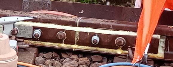
For these track circuits to work, sections of rail need to be broken up with insulated joints to allow more accurate location data to be provided. These are known as Glued Insulated Joints (GIJs), as shown in the picture below) and come prefabricated into a section of rail 3.43m or 4.57m long (or specially made if required). These are tested under factory conditions to ensure they function correctly. To fit them, a section of the existing rail has to be cut out and the new prefabricated section is welded into place. This falls to the civils team.
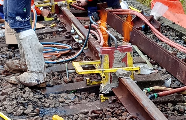
A single use mold is fitted over the gap in the rails and rubbed in place to shape it as closely as possible to their worn shape. It is then sealed with a clay mix and an oxyacetylene torch is used as a preheating flame to warm the rails that will be joined (to 1000 degrees) and to fire the clay.
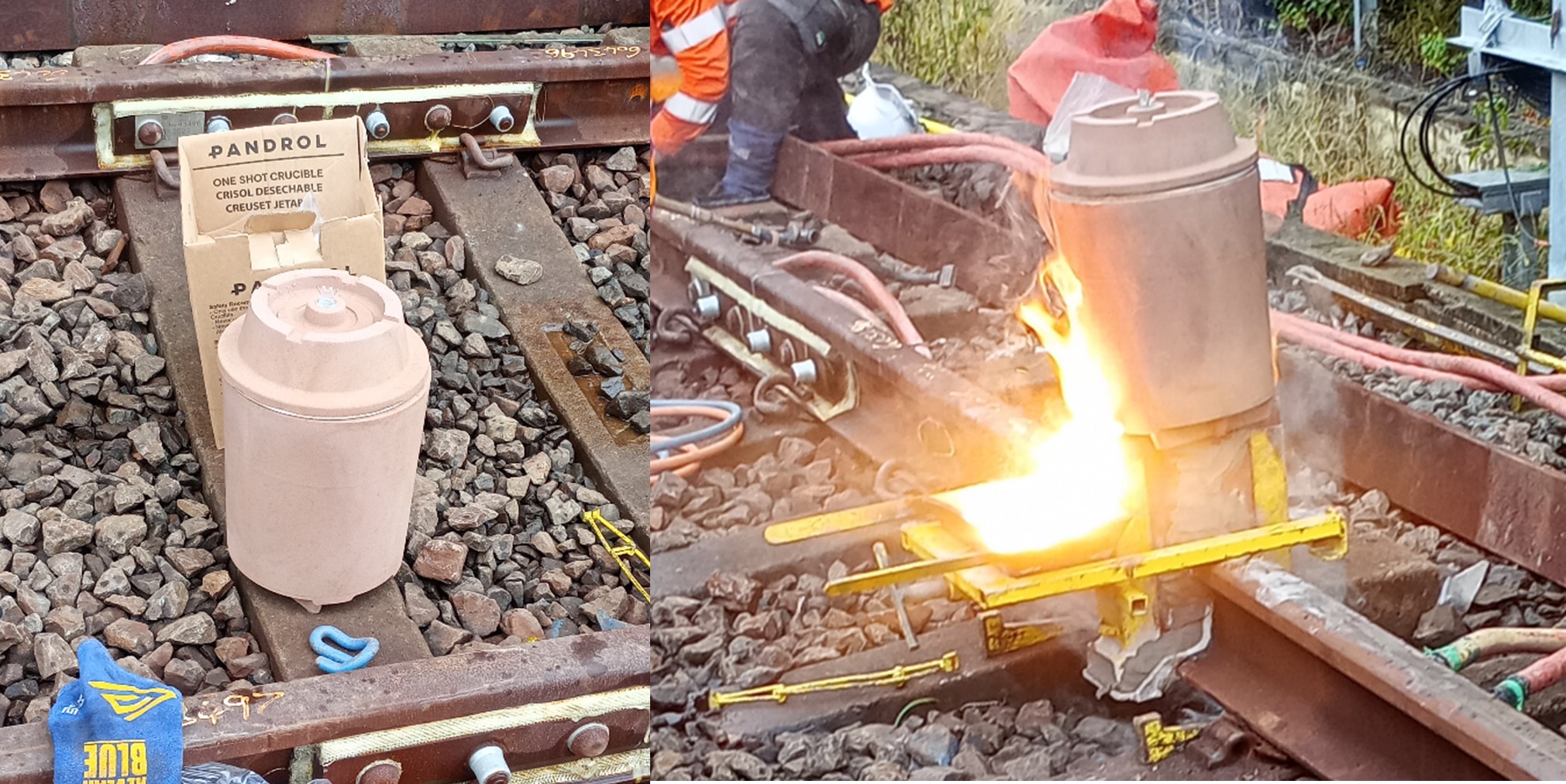
A single use crucible is then placed on top and ignited by sparking between the two prongs of an igniter fuse. The crucible’s filling consists of 37% aluminium, 13% steel, 37 % iron oxide and 13% alloying. This mixture is known as thermit and when ignited a reaction takes place that raises the temperature of the contents to 2500oC within 30 seconds. This reaction creates liquid steel which sinks to the bottom of the mold and liquid slag that rises and overflows into the slag tray.
This is then allowed to partially cool before a hydraulic trimmer is used to shear off excess material and break away the mould.
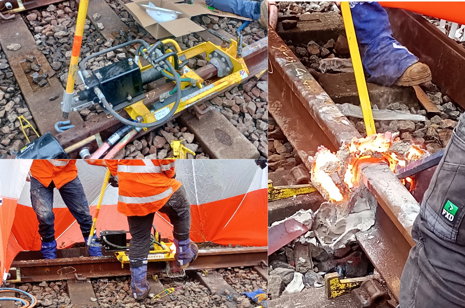
A rough grinding is then carried out using a spinning grinding stone that can be raised and lowered. The joint is then allowed to cool to ambient temperature and shrink completely before a finishing grind is carried out. This prevents a dip forming that would mean the joint has to be cut out and replaced (as the acceptable vertical tolerance across the joint is only 0.3-0.4mm across the two rails). This is checked using a straight edge.
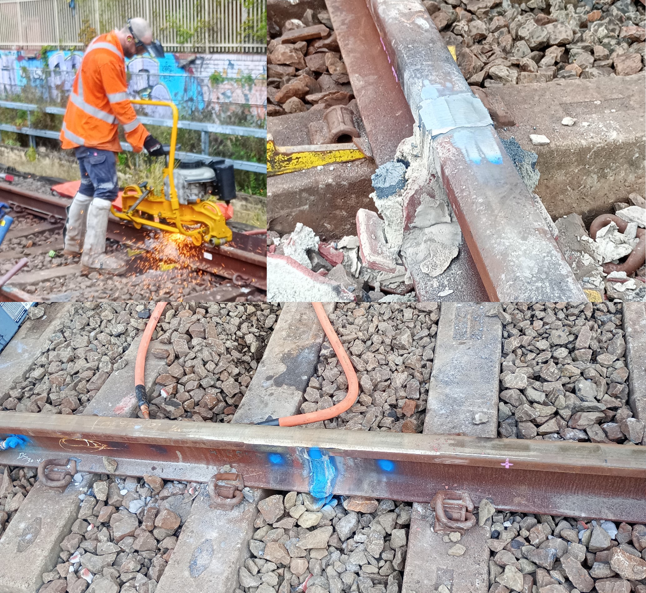
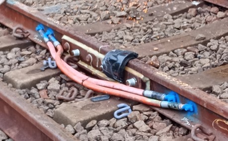
Cables are then welded either side of the GIJ. These are left bonded when it is not in use and will be removed once the signals have been commissioned.
Key takeaway
Rails may be live even if it the power lines are overhead and have been disconnected – no metal measuring tapes in the rail corridor!

This video from Jacobs is very powerful and explains the potential tragedy that can arise through using metal tapes worth a watch and showing to people on site …
https://www.youtube.com/watch?v=hRr0Euf1Yrk