Archive
HELP
Does anyone know anything about HV installations in Camp Bastion and/or Camp Leatherneck?
A Channel 4 documentary reliably informed me that the ES compound had a HV system, but TICRE has no info on it. So if anyone can point me in the right direction, or even just make up some thing that I can then reference that would be great. Thanks.
Water, water everywhere…things that I have learnt about hydraulics
Summary of Secondment to Warren Smith and Partners
Introduction
Following last week’s update on all things mechanical, this week covers my secondment to Warren Smith and Partners, the project’s consultants for Hydraulics, Dry and Wet fire system. In addition they also have departments for civil and stormwater drainage design. I benefited from this design secondment in 3 areas:
- Extending technical knowledge of services engineering.
- Reinforcement of theory and knowledge from PET course.
- Practical aspects and implications of theory.
Aim of secondment.
The aim of the secondment to WS&P was to develop a thorough understanding of the processes used for the design of hydraulics, dry and wet fire services and civil and storm water drainage.
Timetable.
- Monday 17 Oct 16 – Civil: Storm water and drains. Inc site visit to domestic development.
- Tuesday 18 Oct 16 – Civil: Storm water and drains. Inc. site visit to Barangaroo development.
- Monday 24 Oct 16 – Hydrant and potable water. Fire (Dry/Wet).
Key documents.
- AS 1670: Fire detection, warning, control and intercom systems – System design, installation and commissioning.
- AS 1851: Routine service of fire protection systems and equipment
- AS 2419.1: Fire hydrant installations.
- AS/NZS 3500: Plumbing and drainage
- Part 1: Water services
- Part 2: Sanitary plumbing and drainage.
- Part 3: Stormwater drainage
- Part 4: Heated water services
- Australian Building Codes Board: National Construction Code 2014 Volume 3.
Overview of secondment.
Storm Water Design. WS&P uses two main programmes for design; DRAINS to model the catchment area and storm water runoff design; and MUSIC (Model for Urban Stormwater Improvement Conceptualisation) for stormwater treatment.
The outputs of DRAINS are used for the modelling within MUSIC. I undertook a short design exercise using MUSIC based on the Barangaroo Reserve Development in Sydney – the area circled in the figure below was an old industrial dockland and was converted to a public space and nature reserve (the hill is entirely man made). The requirement was for a reduction of >80% for total suspended solids, >65% nitrogen and >45% phosphate. Using a combination of onsite detention tanks, swales, filters and bio-retention I achieved this. Following the site visit to the Barangaroo Reserve development I believe I would have been able to further refine my design to remove some of the filters, thereby reducing the council’s ongoing maintenance burden for the stormwater system.
Figure 1: Barangaroo reserve development can be seen in the foreground.
The New South Wales government states that the minimum requirement for post-development flow be no greater than the pre-development flow. However, each local authority can set more onerous requirements. For example, Hornsby Council in Northern Sydney states that the 20 year post-development flow must be less than the 5 year pre-development flow. Understanding the local restrictions is therefore vital.
The site visit was to a small scale residential development where a plot was to be split in two and both plots developed. The purpose of the visit was to ensure that all parties were aware of the implications of the requirement to meet Hornsby council’s post-development flow standard, to ensure that there was sufficient mains pressure and to comply with the water authorities’ requirement for both plots’ waste water infrastructure to be entirely separate. This latter requirement caused issues for the routing of the drainage from the second plot to the sewer system that would require the removal of community trees – this brought in another set of regulations about tree removal. As highlighted in the paragraph about, a thorough understanding of the local restrictions is vital.
Hydrants, hose reels, sprinklers and drenchers. All the requirements for fire equipment are based on the size, construction and use of buildings as well as the available mains water pressure and volume flow rate. The requirements are laid out in the National Construction Code of Australia, the structure of which also acts as a flow chart to assist in the development of the building design.
- Part A: Classification of building.
- Part B: Structural provisions.
- Part C: Fire resistance (classification, number of levels and volume of building)
- Part D: Access and egress.
- Part E: Services and Equipment. During the discussion about sprinklers it was clear that WS&P’s position was that as sprinklers control 90% of fires, they would, where possible, use sprinklers in their designs even if not stated in the code. This position is supported by the fire brigade and their inspection authority that have closed loop holes that allowed for the exclusion of sprinklers under certain circumstances.
In addition to the codes and requirements for fire equipment, the important installation features were discussed:
- Sprinkler heads are to be unobstructed in order to allow the sprinkler envelope to form.
- Flexible sprinkler pipes have a given bend radius. During installation it is usual for other trades to move the flexible hoses and possibly cause damage. This must be checked.
- Within ceiling voids, sprinklers also act as fire detectors, therefore removing the requirement for a separate ceiling void detection system.
The first two of these points have been useful during my quality assurance inspections.
Potable Water. WS&P uses PIPES for modelling all hydraulic designs – potable water, fire and hydrants. As potable water is an open system, unlike a heating system where the water can be treated, the constant flow of water degrades the pipes – oxidation and erosion – therefore the recommended circulation flow drops to <0.6m/s. Delivery flow can be greater and in line with the CIBSE values.
During schematic design the water authority provides details of the flow and pressure within the mains, the final design should consider the following factors:
- Minimum amplification of existing infrastructure.
- Minimum disruption to routine function of mains: from both connection to mains and location of connection.
- Reduction of mains connections as each one occurs routine service costs to the end user.
- Pumps requirements: If mains pressure is under 250kPa then a pump is required.
- Pressure reduction requirements. The max pressure at an outlet is 500kPa therefore pressure reduction may be required. Where there is a large step down, this should be done incrementally with reductions of between 25 and 50%. Best practice for preventing oversizing of RPZs is to install 2 in parallel (each designed for 50% flow) with a small bore (15mm) bypass.
Smoke Control Systems. As detailed from the Fredon secondment, the mechanical consultant produces the Fire Fan Control Matrix. This stipulates which fan has to do what in the event of a fire – the Fire Fan Control Panel and the Mechanical Control Centre are then programmed to enact this. It is important that all stages of the fire design involve both the Mechanical and Fire designers, and as stated earlier it is important to have a clear delineation of roles and responsibilities.
The Emergency Warning Intercom System (EWIS) for a hospital must be set up to minimise distress to patients. Therefore at the St George Hospital there are no speakers in the patient rooms, but to ensure that there is sufficient warning in each ward an additional mimic panel has been added at each Nurse’s Station. Therefore in the event of an evacuation the nurses are aware but immobile patients are not subject to the distress caused by listening to the automated evacuation warning instructions.
AS1670 covers fire rating copper cables, but not optical fibre. This gap is currently being resolved.
Key lessons learnt.
Standards must be fully understood, but also there is a requirement to be cognisant of the other national, regional and local regulations. The consultant’s value is clear in their expert understanding of all the levels of codes etc.
Design conditions for all circumstances must be understood – for example the difference between the potable water circulation flow rates and the acceptable distribution flow rates.
Designs should be optimised to reduce the end user’s maintenance requirements.
Recommendations.
With the wide range of expertise within WS&P, it could be an option for future Phase 3 attachments.
Psychometric charts are not all straight lines…and other things that I have learnt about Mechanical Systems.
Summary of Design Secondment to Fredon.
Introduction
As I am not completing a typical Ph2/Ph3 attachment, I have been trying to bolster my B (Design) competencies by undertaking short design focused secondments away from Mulitplex. Fredon are the mechanical sub-contractor for the St George Hospital Project and as such design and install all the mechanical building services. In total I spent 5 days with Fredon at their design office. I benefited from this design secondment in 3 areas:
- Extending technical knowledge of services engineering.
- Reinforcement of theory and knowledge from PET course.
- Practical aspects and implications of theory.
Aim of secondment.
The aim of the secondment to Fredon was to develop a thorough understanding of the processes used for the design of mechanical building services – starting out with heat load modelling and concept design then eventually finishing with the detailed design of all the necessary elements of the system ready for installation.
Timetable.
- 5 Sept 16: Overview, heat load modelling using CAMEL.
- 6 Sept 16: Heat load modelling using CARRIER, air distribution and smoke exhaust systems.
- 12 Sept 16: Psychrometrics.
- 13 Sept 16: Cooling, balancing and valves
- 22 Sept 16: Electrical and building management. Value engineering
Key documents.
- AS1668-1: The use of ventilation and air conditioning in buildings – Fire and smoke control in multi-compartment buildings.
- AS1668-2: The use of ventilation and air conditioning in buildings – Ventilation design for indoor air contaminant control.
- AS3000: Electrical installations.
- AS4254: Ductwork for air-handling systems in buildings.
- BSIRA Rules of thumb.
- TS11: New South Wales Engineering Services and Sustainable Development Guidelines
Overview of secondment.
Design fundamentals. The key considerations before starting the mechanical design are:
- Thermal zones and environmental conditions. Australia is split into 8 thermal zones, each one with its own requirements for typical equipment and insulation. For example Tasmania requires heating, insulation and limited cooling, whilst Cairns requires significant cooling and no heating. In Australia the peak thermal loading occurs on the NW face of a building at 1500.
- Occupancy and use of building. AS1668 covers the requirements for certain building usages – for hospitals a theatre must have 20 air changes, the ED only requires 10. The occupancy of the building also changes the acceptable envelope of conditions.
- Type of building. For example in residential construction there are 5 grades of building. Grade 1 is the highest quality, Grade 5 the lowest. Clients and end users of the former will have far higher expectations of performance and quality than the latter where merely conformance with minimum AS1668 standards is required.
- Scale of the project. The scale and the life span of the project are key variables in the selection of mechanical equipment – at the smallest scale (100kw) with the shortest lifespan (25 years), a 4 pipe chiller system, with boilers for heating, will be required – the increased capital expenditure on this system will be balanced by the lower operating expenditure.
- Smoke management systems. These life critical systems are fundamental to the overall design, but due to their size and performance requirements they are also expensive. If possible, and if understood early enough in the design process then it may be possible to combine the smoke management system into the HVAC system. This point will also be covered in value engineering.
- Location of plant. This is often at the whim of the architect, but the placement of plant can have a very large effect on the operational costs of a structure. For example placing the MME close to the HV substation allows HV plant installation and the associated cost savings. Placing the plant rooms high in the structure increases the cost of the building due to the additional loads and makes replacing MME more difficult.
- Tracking and refining assumptions is critical to intelligent and accurate design.
Design software: CAMEL and CARRIER.
- During the design exercises, it was reinforced that the initial design conditions were paramount to the design’s success. Three phrases were used that I had not heard before:
- The outputs from the software are usually compared to results from previous projects and from rules of thumb calculations, Fredon do not routinely undertake hand calculations to check the results. The Fredon engineers also highlighted that both of the programmes were very conservative. CAMEL has the option to add a project safety factor; however this feature is not used as the results, by nature of the conservative model, already have a significant safety margin. In addition, the diversity used by both programmes is limited by the conservative nature of the models. As a result of this, it seems that the model is used by the senior engineers as a guideline to steer their design rather than the actual design tool.
- I completed short design exercises, based on the St George Hospital project, with both programmes. The user interface of both and the methodical process of adding the required information for the heat load calculations meant both were easier to use than HevaComp. Although the inability to import CAD drawings, and only produce 2-D results was surprisingly limiting. Once the heat loads are calculated, it is also possible to design the cooling and heating plant required for each zone/area.
- Both heat load design suites used by Fredon are 2-D only models and require the designer to input the size, shape and construction of the rooms within the building. CARRIER is a globally used design package, whilst CAMEL is the most commonly used modelling software in Australia.
- Critical design – design for the worst case.
- Comfort design – design for the average case.
- Coincident wet/dry bulb temperatures. Peak dry bulb temperatures to not occur at the same time as peak wet bulb temperatures, and vice versa. The corresponding wet bulb temperature at the peak dry bulb is the “coincident” wet bulb temperature. For example, in a design for Sydney in summer with a high air change rate it is important to use the peak wet bulb temperature and coincident dry bulb temperature as the WBT will be most critical to the design.
Air distribution systems.
The design of the air distribution system is based on a number of factors – the building’s layout and space for mechanical services; the volume of air required, number of zones and the type of load. This final factor will affect the equipment selection:
- CAV: Constant air volume. Steady loads, usually equipment loads rather than people. Small systems. E.g. clinical areas and laboratories. The temperature is controlled whilst the air volume is constant.
- VAV: Variable air volume. Changeable loads, usually from people rather than equipment. Air temperature remains constant (reheat coils can be added). High degree of control is possible. For VAV systems, it is important that the control unit is located in laminar flow so the flow can be accurately modulated – the engineers ensured the control units were preceded by 1m of straight duct. Turbulent flow over the control unit will cause it to constantly change the flow.
- VVT: Variable volume and temperature. These, more complex systems, are more expensive but provide greater control options and better responses to changing conditions.
- CRAC units: Computer room air conditioning units. The classification of the data centre (Tier 1-4) will define the spare capacity (safety factor) and redundancy of units required.
Psychrometrics/cooling/balancing. The periods spent on these subjects, as mentioned in Para 1 reinforced the theoretical lessons learnt during Phase 1 and with reference to the St George Project gave real-world examples of their application.
- The most shocking revelation was that all lines on the psychrometric chart are NOT straight – during cooling the line is horizontal until the relative humidity reaches 75% at which point condensation and therefore latent cooling begins and the line starts to curve (see below).
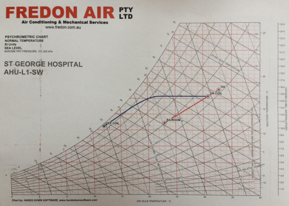
Figure 1: Psychrometric chart – not all lines are straight
- Every AHU within the hospital has been modelled separately – the understanding of these charts and the importance placed on them is clear amongst all the Fredon engineers.
Electrical and Building Management Systems. There are 3 major categories of equipment within the buildings:
- Life safety: Systems that are critical to maintaining lives in an emergency. Smoke fans, fire systems, AHUs and associated equipment for clinical areas and life support machines. The standby generator MUST be sized for 100% of all the life safety systems. In an emergency these systems are set to run to destruction. Life safety systems are covered in AS1668-1.
- Essential: These are not stipulated in AS1668, but instead are client requirements for equipment that is to be supported by standby power. Will often be connected to UPS to maintain power until the generator is running.
- Non-Essential. All equipment that is not required to be supported by standby power.
The contracts for the mechanical and electrical contractors must clearly define the division of responsibilities – usually divided either side of the Motor Control Centre (MCC). Although not applicable to the mechanical contractor, this point has been reinforced during the project between the hydraulic and electrical sub-contractors; the wiring of the Temperature Mixing Valves was a grey areas between their two contracts as no clear delineation was made, therefore they both excluded it.
With the building management system (BMS) the logic must be correct and tested prior to installation, therefore any issues on site are installation related rather than logic related. It is also far easier to resolve the logic during testing rather than using live equipment. Every item of equipment should be included and have a unique tag/number and linked to all associated equipment. It is also vital for the client to be involved in the BMS design to ensure that the required information is available on the system.
Value Engineering. The points below are key value engineering factors discussed.
- Increase ΔT (up to 12°C), many designs are conservative and only use 6°C, but modern equipment can easily sustain greater values – this saves both capital and operations costs.
- Adjust temperature envelopes to reduce the overall heating or cooling requirement; for example is it necessary to cool an office to 18°C when 20°C may be acceptable.
- Remove unnecessary plant or compromise to remove plant that will be very rarely used; e.g. there is no requirement for heating units or boilers in NSW shopping malls.
- Robust QA processes to reduce reworking.
- Simplicity of design speeds up the manufacture and installation process. It also reduces the need for meetings, reviews and workshops.
- Peer review of design to test assumptions, identify flaws and to increase simplicity.
- Overlap of design between trades; e.g. use of domestic hot water for VAV heating. In Australia domestic hot water is the scope of the hydraulic designer and subcontractor not the mechanical. However, where VAVs require only a small degree of re-heat it could be possible and more efficient to use domestic hot water lines to provide this rather than running separate mechanical hot water lines from separate boilers.
- Location of MME to reduce cabling and ductwork.
- Reduce split units and fan coil units for small or unique areas and replace them with well-designed AHUs from central plant rooms. This reduces CapEx, OpEx and maintenance burdens.
- Combine the air handling systems and the smoke exhaust systems early in the design (if possible) to reduce the cost and space of two separate systems.
- The installation of variable speed drives can generate large OpEx savings. However, VSDs do not work effectively at below 30%, if the system requires this then a bypass is needed to keep sufficient air flow through the VSD to maintain the min 30% demand.
Key lessons learnt.
Environmental knowledge and appropriate design for the conditions. Templating of design solutions does not produce efficient designs. The example given was British engineers installing heating systems into buildings during the early developments in Singapore. This is very relevant to PET designs for camps/infrastructure in different regions – this point links to the Phase 1 lectures on the same subject.
Knowledge of scope and expectations: It is important to read between the lines of a scope and make the engineering judgements to match expectation. Where the scope is not clear, then ask for further clarification or make design assumptions very clear.
Track and refine all design assumptions throughout the design process.
Start value engineering as early as possible in order to maximise the benefit and to ensure that others trades can be included.
BIM/Revit: The biggest challenge that Fredon’s engineers mentioned with BIM was the ability of their CAD users – they are computer literate and experts in CAD but they are not skilled draughtsmen, they cannot solve the engineering problems that appear, they can merely draw them.
If a picture paints 1000 words, then this is a 2002 word summary of 2016 on the St George Hospital Project…
April:
Dec:
Merry Christmas and Happy New Year.
James
Attention blog administrators.
The blog memory if currently at 99.9% of its 3GB capacity, if we reach 100% there can be no more blogs………..
My slightly unorthodox Ph2/3
It’s nearly November and I guess most people are starting to get towards the end of their site phase and are looking forward to a bit of leave and then the design phase (hopefully one or two people are thinking about growing a moustache). Early on in my attachment I decided to try something a bit different and sought to combine both Phase 2 and Phase 3 into one Phase 2.5. There were a couple of key drivers for this:
- The project is due to complete in June 2017, so I would be able to see the services element of the project from design development, to installation and through to commissioning and handover.
- When I joined the project there was still a significant element of design development going on: everything from high level services coordination and clash prevention, to user workshops to refine whole room layouts and to finalise designs for key elements within the clinical spaces. This meant that there was initially very little on-site activity for services but it also gave me exposure to some of the design competencies very early on.
- The services manager on the project wholeheartedly embraced the concept of the attachment and was able to organise attachments with subcontractors and consultants in order for me to gain exposure to detailed design concepts, requirements and software.
- The possibility of an extended secondment to Multiplex’s head office to work within the New Projects Department for exposure to the commercial and contractual elements of tendering and resourcing multi-million dollar projects. This has recently been confirmed and will be timed to coincide with the production of my draft thesis.
So far everything has been running fairly to plan – below is a snapshot of these I think I will be come the end of my Ph2.5.
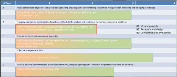
I have highlighted the B competencies in the chart as I believe that of the 5 areas, the design will be my weakest come Ph4 and I will be relying heavily on the experiences gained during my 18 months working in an Oil and Gas design office before joining the army, the design development work from the St George Hospital Project and the short secondments to subcontractors and consultants.
Despite possibly leaving me slightly exposed in the B competencies, I believe that the experience of seeing a project from start to finish will greatly out-weigh the lack of detailed design experience. And I guess if I am wrong then I will just have to come back to Oz and give it another go!
St George Hospital Project
The clip below is a 1 minute animation of the St George Hospital Project – don’t be surprised to see this again at the beginning of my presentation during Phase 4!
Also, if anyone from Phase 1 is interested in knowing a little more about the travel/timelines/admin etc for placements in Oz I am happy to help (or at least try to help). Either leave a comment, or drop me an email: james.stewart.grant@gmail.com.
Friday routine
Unfortunately due to the amount of services design development still required on the St George Hospital Project (we had our topping out party this weekend, so the fact we are still designing the services is worrying) I do not get to spend that much time actually on the site. Instead I find myself doing a large amount of work for sub-contractors to get their designs and documentation correct and sitting in user workshops where different sets of users change the decisions that were made the week before. However, every Friday I am set free from the office for the critical job of witnessing the Fire Damper testing – this is not quite as glamorous as you might expect. The picture below shows my typical view for most of the test:

That’s Gary, he’s from the Mechanical sub-contractors and actually does the test. Once the damper has been dropped I then get to check it correctly closed the duct, if I am really lucky he even lets me rest the damper.
So rather than waste too much time staring at Gary’s bottom, I take the opportunity to look for defects in the installation of the various trades. Usually this is to do with penetrations through fire walls. The top 2 images below show cabling in fire walls that is not spaced at the mandated 200mm (the top left is difficult to see as the offending cables are pink).
The bottom left image shows a fire collar that has been used to attempt to hide a very large gap between hydraulic pipe and fire wall. The final image shows a fire damper penetration that is 7mm too big – and apparently 7mm is a big deal!


In line with Doug’s theme of things that went wrong this week…
When plasterboard meets water.


When there is no space for concrete in the slab because it is full of conduit.


Stay tuned for next week’s exciting episode that will feature Asbestos and a H&S person who expects me to have samples taken for every 25m^2 of a 125,000m^2 hospital: at $200 per sample, that is a nice round $1,000,000!
Oh well, at least it is the weekend…
DAS and Wifi survey
In order to further procrastinate from the job in hand, I thought I would write a quick blog about it and ask for pointers from anyone that has done something similar.
I have been given the responsibility for managing the tender, survey and installation of a new campus wide DAS (mobile phone coverage) and wifi system for the hospital’s existing buildings. We have been given 5 weeks to survey the hospital, given that most of the drawings are sub-optimal (see link below for a wonderful example of what I am working with) the survey will also involve an architect’s surveyor to update existing drawings or generate new ones.
We have 122,000m2 to survey and 25 days to complete it, therefore we have to maintain a rate of approx 5000m2 per day, inside a live hospital just to keep to the original timetable. Add on top a PM who wants to complete everything early.
Whilst this should be a “great learning opportunity” and will cover all sorts of IMechE competencies from design to QA to financial it is starting out as a bit of a head-ache due to all the unknown-unknowns.
In order to help expose some of these unknowns, a bit of assistance would be great. What else should I be considering whilst planning the survey stage:
- Low hanging fruit to get ahead of schedule e.g. corridors, open spaces, offices.
- Restricted access areas that will delay timetable.
- Areas that don’t need DAS and/or wifi which can be ignored.
- Asbestos and hazardous substances.
- Access/working at height.
Thanks in advance for the help….
Generator power
Last week one of the small projects that I have been planning since I arrived finally finished – transferring the Emergency Department (ED) onto generator power, relocating the sub-mains cables and then transferring the power back to mains.

Figure 1: Delivery of 2x 350kVA Aggreko Generators.

Figure 2: Original location of the ED sub-mains, on the floor slab of L1 (previously this had been the roof slab of the 1 storey ED). Note, the mechanical protection has already been removed.

Figure 3: New location of ED sub-mains: Now on high level cable trays in main corridor.
Rather than detail the whole process, I will instead highlight some of the risks and difficulties and how these were overcome.
- The ED runs 24/7, therefore there is no convenient time to turn off their power. But following a week long investigation of power demand, Tuesday-Thursday was identified as the period of the lowest demand and therefore the “least busy period”.
- Sizing of generators: Both 350kVA units was sufficient for the whole department, but to maintain redundancy 2 units were connects – one to Essential and one to Non-Essential (with an automatic switch between them in case of any issues).
- The hospital’s UPS (Uninterruptible power supply) was broken, therefore if power was cut all the critical infrastructure, e.g. life support machines, would switch off. This little bombshell was dropped at 1600 on the Friday before the works was due to start. The simple solution was to postpone until the UPS was fixed.
- During commissioning of the Emergency Department (2 years ago, by a different builder), the generator manual transfer switch was not tested. The risk was the hospital’s to take, therefore they were required to conduct physical switch over – the mains power was maintained at the switch until after the hospital had confirmed that it had worked.
- Fuel: although the generators had a fuel capacity to run for 28 hours at half load, in order to appease the client the tanks were re-filled every 6 to 8 hours. At no point did the levels drop below about 75%. This was a very conservative strategy but keeping the client happy is critical.
- Diesel exhausts blowing into the ED air conditioning intakes. There was only one space that the generators could go – approx 25m from the intakes – other than extending the exhaust flue by 2m (the big pipe on the ground in figure 1), this was a question of keeping my fingers crossed that there would be no complaints.
- Over night noise – the generators were rated at 70 dBA at 7m, but with EchoBarriers installed this dropped to 55 dBA. Although this made us code compliant, at 2am in a residential area it is still pretty loud. This required some more crossed fingers that there would be no complaints.
The overall project success was due to a lot of planning with the various sub-contractor and consultation with the client.
