Archive
Conclusions on Pre-Fabrication
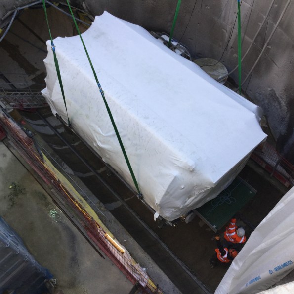
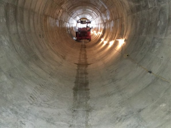
Pre-fabrication and off-site manufacture seem to be very popular in the UK construction industry at the moment and I have lucky to have been the lead on the largest pre-fab install on my project – a 132m long, 4m wide services culvert linking the two buildings currently being constructed.
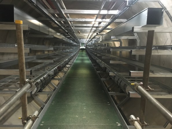
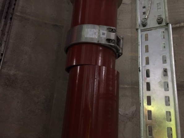
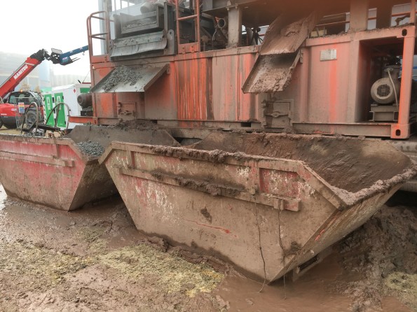
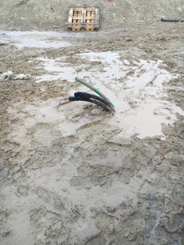
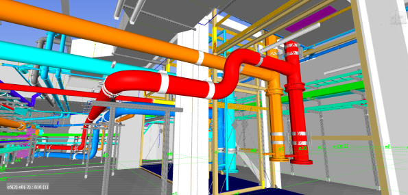
The install consists of 21, 6m long pre-fabricated modules with 12 modules installed on side of a central vertical shaft and 9 on the other. The modules carry chilled water, high-grade hot water, low-grade hot water, mains cold water, boosted cold water, sprinkler supply, HV, LV, ELV, Fire Alarms and Fibre-Optic Data. Water is transported through a series of cast pipes varying in size from 1″ to 16″ and the pipes are connected using Teekay Couples with a fixed point in the centre and expansion bellows either end of the tunnel to allowing for thermal expansion. All pipes are lagged and seated on slip rings. The cabling is fixed to a variety of containment (ladder racking and trunking) as shown in the pictures.

Background
During the procurement process, a study was conducted to consider the use of prefabricated modules in the tunnel rather than traditional on-site MEP install using Unistrut bracketry. This study estimated the cost to traditionally fit out the tunnel to be £745,757. The study concluded that there could be a saving by using pre-fabricated modules manufactured off-site. Since my project uses BIM Level 2, the required module was subsequently modelled in 3D and inserted into the consolidated building model. In my opinion, BIM significantly reduces the design risk when designing complex modules or bespoke structures and for us the ability to model each module in 3D and then move it through a virtual 3D tunnel using the as -built information from a laser scan was invaluable and actually led to the height of the modules being reduced as it was clashing with a low point in the tunnel.
Once the design had been agreed and approved by the Principle Designers (BDP), it was sent to Skanska Fabrications for a mock-up to be constructed.
As the install lead I visited the mock-up a few times and was able to provide feedback that led to design changes that would make the install easier (one such improvement was to set back the low level Unistrut that forms the walkway to give better access to the pipe connections and Teekay couples – you can see the issue in the above photo).
Once the design had been amended and agreed upon, the package to manufacture and deliver the 21 modules was put out to tender and awarded to Balfour Beatty Engineering Services (BBES) for a sum of £460,805. Although this looks like a significant saving on the £745,757 estimated cost of traditional install, other costs need to be factored in before a true comparison can be made. In addition to the manufacture fees, the installation costs (which I tendered under my own package) totalled £86,325, the cost of realigning and connecting the pipe work was agreed at a cost of £55,493 and connecting the electrical containment has been quoted for at a cost of £11,500. This brings the total cost of manufacture and installation to £614,123 which is about 18% less than the estimation of the traditional install and has been hailed as a significant saving to Client. This cost does not take into account the additional cost of designing a more complex system and comparing the costs to an estimation is unreliable as the costs could have been over-estimated. Therefore I believe the actual saving, if indeed they was any, is actually quite small especially since a traditional install would have procured through a 2-stage competitive tendering which would likely result in a contract sum that is less than the estimation.
One of the greatest advantages of pre-fabrication is that you can remove it from the critical path in the programme and reduce the time required for on site install. By manufacturing off site you can manufacture early and store the products rather than having to wait for an area to become free or for interfacing/preparatory work to be completed. However what I have found in reality is that the time to design a pre-fabricated solution is much greater (especially if modelled in 3D using BIM) and so although you may plan to construct early, manufacturing can be delayed by the design and drawing production which is what has happened on my site. In my case, the manufacture was delayed due to a lack of drawings (this is general issue on my project!) and this in turn meant that the tunnel was left empty and ready for the modules while the modules were still be constructed meaning that there was no real time saving. Infact, if we had gone down the route of traditional install then we would have fitted out the tunnel earlier than we did.
A disadvantage of pre-fabrication is that the design needs to be agreed and fixed earlier in the programme which then creates a greater risk from design changes later on.
Installation
The tunnel modules were installed as follows:
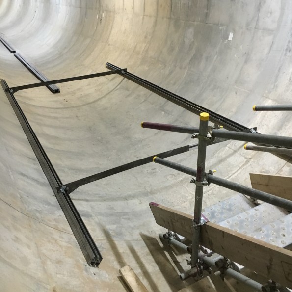
First of all a rail was installed by my sub-contractor using a jig-system:
Then the modules were dropped down the central shaft using a crane and dropped onto the rails:
They were then dragged into position using a winch: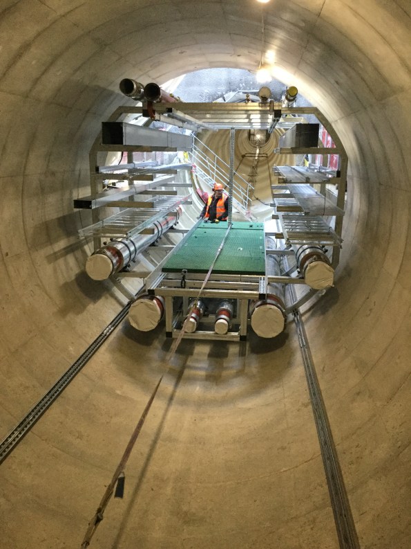
Unfortunately the installation did not go as smoothly as the above description and I had to make changes both to the method and the state in which the modules were delivered. Despite this, we installed the first module on 24 Nov 16 and the last module on 12 Jan 17. Now we have to finally align and then bolt together all of the modules before we can realign and connect the pipework and containment. Then we can also take a site measure and construct the ‘make-up section that sits in the centre of the tunnel and will fix the pipework to the tunnel wall (required for expansion).
Snagging
Inspection of the installed modules has highlighted several issues. The first is that most of the pipework is out of alignment and so will need moving in order to be connected. The mechanical sub-contractor is arguing that the amount moving and aligning required is beyond the scope of their contract and so are requesting an instruction and extra cash. It is my belief that the pipes have moved during transportation due to cyclic loads. The pipes are on slip guides and the slip guides are fixed to the modules using Unistrut channel nuts (zebedees) which rely on friction to provide a fixing. Therefore in theory all of the pipes could move if forces are applied to it outside of the design conditions. A lot of the containment is also out of alignment.
Another issue is that some of the modules do not fit together as some of the walkways and kick plates stick out too far. This makes me question how the modules were jigged at the factory – a concern I have raised with BBES. However the greatest issue with the install is that some modules are sitting noticeably higher than the others. I am still investigating the reason for this but believe it can be only one of two possibilities:
- The rail is high in places which could be due to a poor install or imperfections in the tunnel itself -several were picked up on the laser scan!
- Some modules were incorrectly constructed or mis-jigged.

Either way I need to come up with a solution and so I am looking at ways to reduce the overall module height.
Given the variety of snags and issues, I have assembled a multi-trade team using 4 sub-contractors that will go through each module and adjust every pipe, rack and section of trunking to allow all the modules to be moved as close together as possible which will minimise the gap between the pipework (maximum allowed gap is 8mm). This team will start next week which gives me a few days to work out how to lower some of the modules!
Conclusion and Recommendations
It is my experience that the conventional understanding that using pre-fabrication saves time and reduces programme risk whilst increasing costs is incorrect since on my site we have seen the exact opposite. So far on Project Laureate, using pre-fab has led to on-site delays (with knock on effects on other packages) and has cost less (18% less) than a traditional install. However, it is worth noting that this could be unique to this site due to the scale and complexity of this install or the selection of materials. Also the cost of the traditional install is reliant on an estimation which may not be accurate.
Prior to conducting this task it was my understanding and the understanding of my colleagues that the modules would arrive on site and line up perfectly, reducing the amount of time required for the on-site fit-out. Again this has not proved to be the case as none of the modules fit together without remedial works and extra time is now required for realignment. I would urge anyone running a similar task in the future to assume that any bespoke modular system being delivered to site will need a certain amount of realignment and adjustment on-site. At the very least this requirement should be priced as a provisional sum during tendering and should be included in the programme. This is particularly important for large and complex structures or systems with several variables (e.g imperfections in the final structure or multiple connections).
During the design of a module or pre-fab structure, assume that the structure it will be installed in is riddled with imperfections and plan against this to reduce the risk of delays and additional costs during the install. This could be done by adding a means of adjustment in each axis. Although this will incur additional costs, in the long it will likely save money.
When considering loads on the structure or system, also consider the temporary state such as transportation to reduce the risk of structures deforming or equipment shifting. This could lead to the requirement for bespoke bracing or supports that be will used during delivery to site.
Regularly visit and ask your sub-contractors to visit the factory during manufacture to provide feedback and to facilitate design changes that will make the install easier.
Although this package has proven to be an engineering challenge and is my greatest headache at the moment, would I use off-site manufacture again? Yes I would as I still think if done right it can offer either cost savings or time savings. However, I would implement the points above and would most likely tender it out as a design and build package to reduce the risk of delays due to an overstretched Project CAD Team. If using a Project CAD Team, I would recommend only considering the use of pre-fab for complex installs if BIM is the primary method of design.
Mark, can I count this as TMR 4?!
The Importance of Risk Registers
I am coming to the end of my Phase 2 attachment and I have been lucky to have witnessed the majority of a contract that I planned, tendered and wrote the contract for be completed on site. However, things have not gone exactly gone to plan!
One issue with my package, which is a package to install all heavy plant in the Energy Centre and Tunnel, is that it was planned and tendered before most of the plant equipment had been procured and before the RIBA Stage 4 design had been completed. This meant that under the subsequent stage 5 design, plant positions have changed and the plant itself has generally changed in size and weight.
These changes have pushed the some of the required works out of scope and so the sub-contractor has asked for an instruction to undertake the works and of course extra cash! A saving grace is that I identified this as a risk back in May 16 and so entered it onto the package risk register with an allocated risk of £50,000. On my project, all package risk is pre-allocated by the client with a risk pot allocated for each package. Sadly, not all of the risk I identified was approved by the Client as the Client has decreed that no package risk allocation is to be greater than 5% of the package total which reduced the available risk available for scope changes due to stage 5 design changes from £50,000 to £11,000 – which is not a lot. I do not agree with this approach as some packages will always be high risk and with no means of mitigating this risk to an acceptable level. Therefore the Client is not suitably preparing for future increased costs.
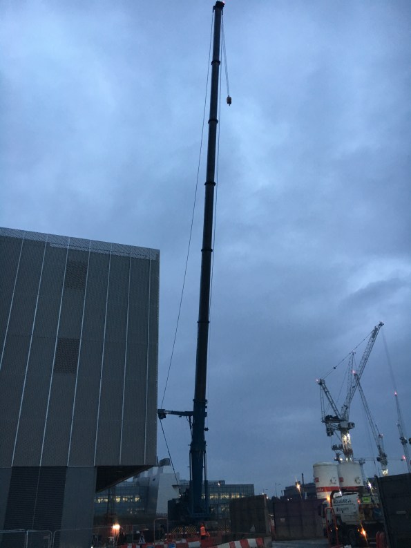
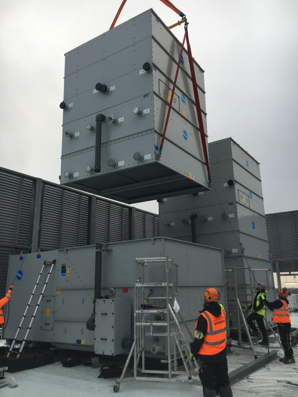
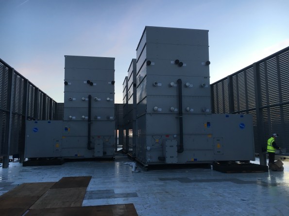
One example of these changes moving a task out of scope and requiring a change request was the installation of the five Cooling Towers on the roof of the Energy Centre. In this case both the position of the cooling towers changed just two weeks before the lift and the mass of the heaviest lift also increased from 5T to 10T as the selected supplier had a different method of installation to that used to estimate the cost of install. The combination of these changes meant that the allocated 150T crane would not be sufficient to suspend the load at the required radius and so a 500T crane was required. A 500-ton cranes requires two additional flatbeds to set and an additional set up fee of £25,000 plus an extra £3,00o for each additional day.
These additional costs were first highlighted to the Client using the Early Warning System and I submitted a change request for an additional £28,000. I had to brief this to the Client and explain why this had not been identified during tendering and eventually the Client agreed to use £11,000 from the risk pot and to publish an instruction with a cost value of £17,000. This meant that the works could go ahead but it has highlighted to me the importance of trying to confirm the scope early or at least over-estimating the scope (e.g oversize the plant) to reduce risk. That said, over-estimating in a fixed price-contracting will inevitably result in larger contract sums and so it is a balancing act to ensure an overall saving for the Client.
It has also demonstrated to me the importance of investing time into the Risk Register since if used correctly, the allocated risk pot can help get you out of a sticky situation and can be a useful source of funds if your scope proves to be insufficient. Ultimately all construction work will involve risk and it is important to both correctly and accurately identify this risk, mitigate it where possible and then allocate project funds to any residual risks. I would recommend pre-allocating funds to all residual risks so the money can be spent as soon as the risk materialises as any delays securing funds through change control will likely take time (at least a week on my site) and this in turn will likely increase overall costs and impact the all-important programme.
Anyway the cooling towers were successfully installed with the 500-ton crane:
But unfortunately I was not happy with the install during the QA inspection due to the misalignment of the Anti-Vibration Mounts (AVMs) and so raised this an issue with the sub-contractor.
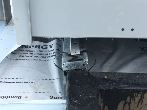
During the inspection I identified that the AVMs were incorrectly handed which was causing the AVMs to rotate. I therefore got the supplier to visit site to inspect them and they have since admitted fault and will be replacing the AVMs in March/Apr – a task that will likely fall to Will Stott to lead on during his attachment – enjoy!
How to construct a geo-thermal borehole
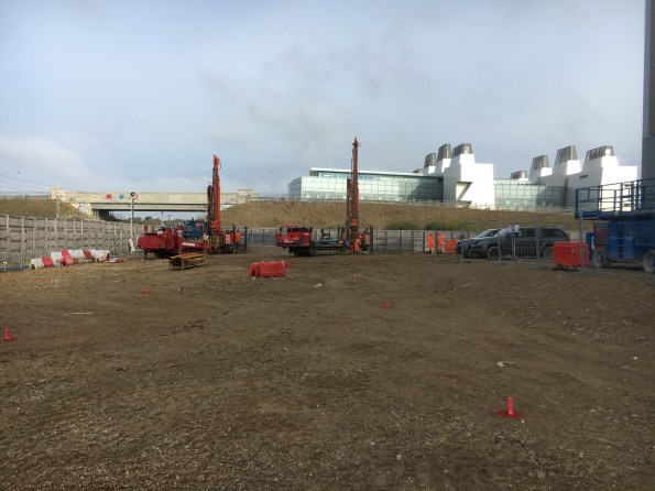
I am now three weeks into the construction of what will be the UK’s largest geothermal borehole field with 170x 200m deep Boreholes.
So here is the rough method of construction:
Install a 6m casing to protect the top of the borehole.

Using a specialist drilling rig, bore down 204m. Throughout the drilling, clean water is pumped into the borehole to reduce the temperature and help remove the spoil.
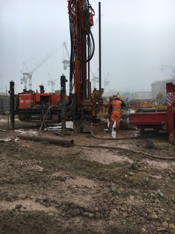
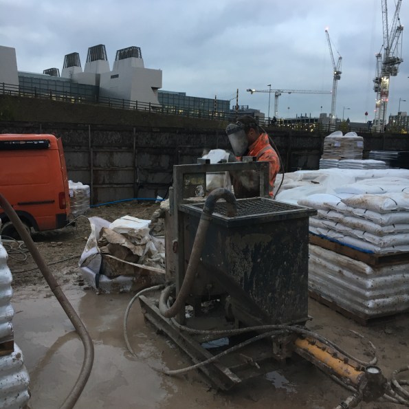
Once at depth, recover the drill rods. During this phase, the rejected water is collected and pumped to a mud-cleaner so it can be used to drill the next borehole or can be used to flush the borehole. The mud-cleaner adds a coagulant to help remove the fine solids and the slurry is then passed through two screens to remove the larger muds (On the let hand side of the mud-cleaner). Then the slurry is put through a centrifuge to remove the fines down to a size of 4microns. The clean water is then stored in the tanks along the bottom of the mud-cleaner or the reserve tank. The mud removed from the water is deposited in skips for off-site disposal.
Remove the muddy water and replace with clean water to reduce the buoyancy of the pipework. This is known as flushing.
Drop 2xpipe loops and a sacrificial pipe (green tremmy pipe) down the bore. To reduce the buoyancy of the pipework, the pipes are filled with water and a 230kg sacrificial weight is connected to the end. The pipe are installed using a specialist spool and a telehandler.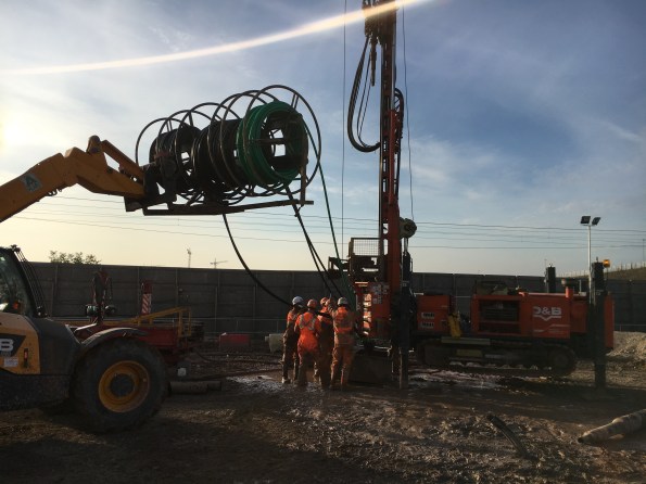
Pressure test the two pipe loops. Both u-shaped black pipes are tested at 8 bar for 30mins and then at 4 bar for 1 hour. Initially the pressure will dropped as the pipe expands and so the pressure is topped up. Towards the end of the test, a reduction in pressure points towards a leak.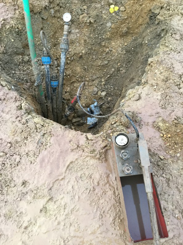
Flow test the pipe loops to check for blockages.
Backfill the borehole with thermal grout. This grout consists of bentonite and Chelmsford 52 silica sand with a silicon dioxide content of 97%+. Just enough water is added to the grout to make it ‘pumpable’. on my site we are using a 5.5 to 1 sand-to-bentonite ratio as this gives a thermal conductivity of 1.8W/Km2. The grout is mixed in a hopper and a sample is taken at random. The grout is pumped to the bottom of the borehole through the tremmy pipe which means that during filling, the water in the borehole is pushed up and rejected. This water is collected and pumped to the mud-cleaner to be cleaned and stored for future use.
So that is how to construct a vertical heat exchanger for a Ground Source Heat Pump System. This is the end result ready for the horizontal pipework to be installed.
Bloody Boring
A while ago I was appointed the lead for the construction of a £1.2m borehole field for a Ground Source Heat Pump (GSHP) System. This has been a challenging task as it has meant working closely with an Austrian Sub-Contractor and numerous Sub-Sub-Contractors to design the field.
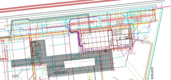
The borehole array design has taken 3 months to develop and finally sign off for construction. The final design is for an array consisting of two fields totalling 170x 200m deep boreholes arranged at 6.5m spacings. The design also includes six monitoring boreholes that will allow us to measure any heat flow between our borehole field and the two neighbouring borehole fields as it is a real risk that ours could steal heat from our neighbours and so result in financial penalties.
The normal recommended spacing between boreholes is 7m due to boreholes not being straight and to ensure suitable heat storage. The sub-contractor calculated that a spacing of 6.5m was acceptable in terms of heat flux density and that the boreholes would not collide at 200m. However using this figure gives very little room for error and so once placed in the borehole array lattice, the boreholes are fixed as any movement would reduce the separation below 6.5m and risk the boreholes colliding at depth. The design has proven to be a challenge and so several weeks ago I decided to split it into two smaller designs so at least a section could be approved for construction without delaying the start on site date. This has led to a two phase construction programme with the design for the second phase currently in abeyance. Here is a drawing of the finished design with the myriad of constructed and planned underground services:
The main issues for this prolonged design period has been:
- Buried Services. Generally borehole fields are constructed on virgin sites and so services aren’t an issue but due to project delays and a last minute change of sub-contractor, our borehole field is being built around existing services including drainage, attenuation tanks and HV/LV cables. Deconflicting the boreholes and services has been a real nightmare and taken up a surprising amount of my time. If I were to be involved in constructing a borehole field again I would push for the array to be constructed as early as possible and before the majority of underground services.
- Future Landscaping. We have also had to change the array design to take into account the future landscaping so that the boreholes and connecting pipework will not be damaged by tree roots or will not sit in ponds.
- Principal Designer. Since we are not the Principal Designers, all designs have to be signed off or agreed with the designers, BDP. BDP very rarely visit site and do not have a great understanding of the borehole design nor the work involved in its creation. This has resulted in designs being rejected with BDP requesting investigations to be conducted despite this work already been conducted by my team during the design development.
- Technical Submissions. The Sub-Contractor submitted datasheets for my approval and approval from BDP. Unfortunately further investigation showed that the pipes that run through the borehole were not rated to 20bar (the pressure of water at the bottom of the pipe) and the Thermal Grout (Bentonite and Silica Sand) had a thermal conductivity of 1.7W/Km2 whereas the design specified a conductivity of 1.8W/km2 and the thermal simulation was based on this figure. After rejecting the proposed materials, the sub-contractor and their supply chain conducted a number of pressure tests on the pipework and changed the grout mixing ratio.
- Contractual issues. There has been a disagreement about who is responsible for providing power and water and this has forced me to dig into the contract to resolve the conflict. the result was that I recommended that the Client should instruct the Sub-Contractor to supply a generator but that the costs should be borne by the Client due to the Client not performing his obligations under the existing contract. The Client agreed and the instruction was issued through change control. Also we stipulated that the lifting plan for some of the plant machinery had to be written by an A61 qualified Lifting AP as this is Skanska Policy. This meant that the Sub-Contractor had to pay a third-party AP to rewrite and sign the Lifting plan and the ensuing arguments have damaged our relationship with the subbie – something I am keen to resolve. So after scouring the contracts I was able to prove that this requirement was not specified as part of the tender enquiry but was first mentioned after the contract was signed and therefore can only be enforced through change control and at cost to the Client. I am awaiting approval from the Client for this change request.
Anyway, after months of redesign and compiling the mountain of paper work and permits required to get a sub-contractor on site, the sub-contractor broke ground today which is a milestone for our Project.
The Sub-Contractor has deployed two rigs to site and will construct and test two boreholes per day. We are now awaiting the arrival of the mud-cleaning equipment and grout materials before work starts in earnest next week. As well as checking and supervising the daily works, I have just initiated the design of the second borehole field and the inter-connecting horizontal pipework for the first field which is due to be constructed in four weeks.
This experience has resulted in a few lessons learnt:
- Borehole fields should be built as early as possible in a project as services are easier to move than boreholes which have a fixed separation.
- Under Management-Only contracts, the Principal Designer should be included in design meetings throughout the design process to give them greater situational awareness and to streamline the approval process. They may require some ‘motivation’ to get them to attend site meetings!
- Never assume that the materials selected by the sub-contractor are fit for purpose or suitable for the design so interrogate them.
- When writing a contract be explicit as to who is responsible for providing on-site services and ensure the Sub-Contractor acknowledges these requirements during the Pre-Start meeting. Where practical, in the scope document/contract, instruct the sub-contractor to include for the provision of their own power and water and include it as a cost item in the pricing document (BoQ/Volume 3). Then if the Main-Contractor/Client can provide mains water and power, omit this cost as a saving. If this is not possible then ensure that the cost of providing a generator (in case site power in not available) is listed on the risk register so it is still included in the cost plan.
In a few weeks I will blog about how the boreholes are constructed and tested as an interest piece and hopefully this will coincide with the Phase 1 E&Ms learning about GSHPs.
Yesterday we awarded a £1.5m package which I developed from conception and led through tendering and wrote the contract for so I will also blog about two-stage tendering and sealed-bid tenders and my experiences of them. I am trying to get the newly appointed sub-contractor on site on Monday 31 Oct 16 to start the fit out of a 132m long 4m wide services tunnel but this is tight and does not leave a lot of time for pre-start events and approving RAMS and Lifting Plans. So a busy week ahead…..
‘ealth and Safety gone mad
I am trying to complete the mountain of paperwork required to get permission for a sub-contractor to start on site. One of the checks is to ensure that the workers have valid medical certificates to operate safety-critical plant equipment. Anyway these medicals are valid for 3 years but some Health and Safety ‘ninjas’ on my project have stipulated that all medicals must have been completed within three months of starting on site. the subbies I am working with all have certificates that will be 3.5 months old upon starting.
So quite rightly the sub-contractor has challenged this requirement since if this was the case on all sites, then companies would have to have their workers examined up to fours times a year – 8 times more often than an airline pilot! This would also incur additional, unnecessary cost that will inevitably be passed onto the Client.
So I challenged this rule and asked whether it is based on any form of science i.e has research shown that those with a recent certificate have less sick days. The answer was no – the decision was made during a meeting and the figure of 3-months was plucked out of thin air and agreed upon.
You may be able to tell that I am finding this kind of ‘golden plating’ frustrating and so try to challenge it wherever possible.

Anyway, after challenging this with the health and safety team, I have secured approval for the subbies to start on site.
Has anyone else come across similar examples of the H&S Team unnecessarily gold plating the H&S regulations without any fact or logical reasoning behind it?
BIM induced delays
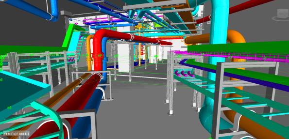
I am responsible for the fitting out of a basement area and so I am trying to sequence the works, using the BIM model to decide the order in which stuff needs to be installed. As such my works programme is becoming pretty complex. Here is a 3D BIM model of the area I have to fit out including all pipework, ladder racks, trays, ductwork and basketry. This task will involve the management of six separate sub-contractors and their interfaces.
BIM is a great tool but very slow and I am finding that the constraint on when I can start each work package is not the supply of materials or availability of sub-contractors but rather the production of construction drawings. So now we are at the point where the drawing production programme is driving and dictating the MEP programme. Due to a lack of coordination at the start of drawing production, the drawings are not being produced in the sequence of construction, causing further delays in several areas and messing with my programme. We have now coordinated with the BIM Team and created a drawing sequence that better reflects what we plan to do on site.
Is this issue unique to our site or common place where BIM is the primary driver of the Building design?
Here is another pic of the basement area showing the complexity of the task:
Sadly, I will not be able to finish the fit out of this area before departing the project and so will not be able to install the whole of the ductwork, smoke extract system, fire alarm system and most of the cable racking.
Factory Acceptance Testing
Like Stu I have recently been involved in Factory Acceptance Testing (FAT) testing but rather than spending a day on a dusty farm, I attended one at the Carrier Test Facility in Lyon, France.
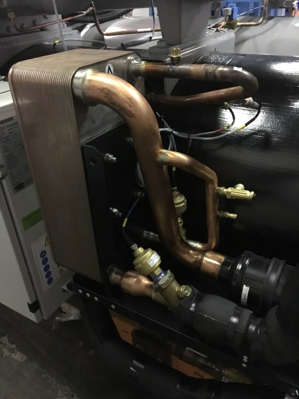
The FAT visit involved witnessing the testing a variable chiller unit. It was a very useful visit as it meant revisiting the refrigeration cycle and learning more about how chillers are constructed. It also included a nice hotel and slap up meal fully paid for by the Client! Here is a picture of the Chiller being tested:

The Chiller is a 1713kW single stage chiller that uses R134A refridgerent and has a Coefficient of Performance (COP) of 4.56. As you can see from the picture, it is in fact two identical chillers bolted together and these two work in parallel and not as a two stage refrigerator. This type of chiller gives better performance at low loads as only one side will be ran. In the picture, the grey cylinders are the condensers and are basically large tube heat exchangers. The condensate is circulated through a closed loop system (45degC flow and 35degC return) that sees it either sent to the cooling towers, heating system or to the boreholes (this system is fully controlled by the building management system being designed by Honeywell). When running at full load, the system provides 2.08kW of heating. The large items on the top are the compressors and the large black insulated cylinders at the back are the evaporators and supply chilled water at 9degC flow using a 14degC return.
Of particular interest was the economiser which I admit struggling to understand fully in Phase One. So here is a picture of an economiser:
As I am sure, all of the E&Ms will remember that the economiser is used to create Sub-Cooling in order to improve COP. It works by diverting some of refrigerant leaving the condenser and then throttling it to the reduce the temperature. This colder flow of refrigerant is then used to sub-cool the main flow using a Plate Heat Exchanger (PHX).
To understand this system, I used a free to download programme called CoolPack. This program allows you to easily plot P-V and T-S diagram and conduct refrigeration calculations. I recommend this program to all E&Ms.
As part of the testing schedule, the chiller was ran and full, 75%, 50% and 25% load. Each time, the chiller was left for 30-45 mins to allow it to stabilise to a predetermined tolerance. Then the system was ran for a further 30mins and the temperatures and pressures were measured and plotted as shown below:
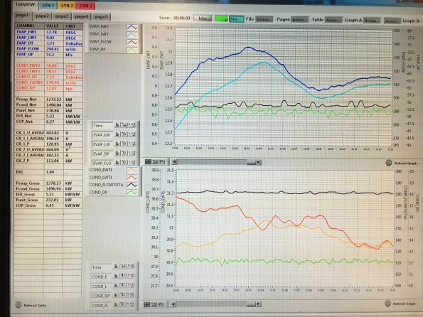
For each test to be signed off as acceptable by us, the chilled water supply and return and condensate supply and return had to be within a tolerance of the design temperatures. Also we checked the power consumption of the system, the heating and cooling outputs and COP for compliance. The Chiller passed all of these tests.
The final part of our testing schedule was to test fault conditions. To do this we increased the system pressure, simulated a loss of power and shut off the cooler pump to simulate a lack of water flow in three separate tests. For each of these tests we reviewed the chillers response such as instantly stopping, allowing the pressure to equalise across the compressor and the messages displayed on the Human Machine interface (HMI). The Chiller reacted correctly in all of the tests but during the high pressure test, one side shut down correctly and displayed the high pressure fault code but the other side shut down but displayed an electrical fault code. So we asked for the test to be ran again but for the faulty side to be ran on its own and this time it displayed the correct fault code after tripping. We also provide carrier with some requests as to how to better display messages and the visual layout of the SCADA system on the HMI.
This proved to be an excellent trip and opportunity to experience FAT testing. It also turned into a very useful refrigeration revision session!
I am hoping to do my next FAT trip to Austria next month and so look forward to a similar blog…….
Fixed Price or Cost Plus?
I am just about to provide technical recommendations to the Client for a £350k plant movements package that I have tendered out and the potential sub-contractors have offered two pricing options for the Client to choose from. Therefore I would be interested to hear other peoples real world experience of these two options:
Fixed Price
We will sign a fixed price contract. This is a low risk option but the package is likely to be subject to continual change meaning that change requests will need to be used extensively and additional costs will be incurred due to out of scope changes, omits and additions. This means that the total cost of the package is highly likely to go over the agreed fixed sum.
Cost Plus
The potential sub-contractors have offered to sell us a set number of labour days (at gang rate) and how we use these resources is up to us. The number of days sold will be based on the current schedule and programme. This option is high risk as we could use more labour and equipment than planned and will have to pay for it but it also offers the Client with opportunity since any savings due to more efficient use of resources and due to not using the full allocation of days will go straight back to the Client. Another benefit of this commercial arrangement is flexibility. Since the package scope is likely to change numerous times, this contract removes the requirement for change requests and additional charges for change since we would simply use our allocation resources for the change. If we do use more than our allocated days of labour and/or plant, additional days will sold at a pre-agreed daily rate.
So does anyone have any experience of these two contractual arrangements and if so how did the final package costs compare to the initial agreed sum?
The importantance of off-site inspections
Nothing significant to report on my site as we haven’t started the installation yet and so we are still in the process of procuring and reviewing RAMS. Personally I have a plant movement package out to tender with the supply chain and I am in the process of reviewing tender returns for AHUs, and procuring some steelwork for some chillers and cooling towers as well procuring a temporary ventilation system for a tunnel – which is turning into a bit a nightmare as the current design does not sit well with the insurers (yes this will become a future blog……..).
Anyway I thought I could post another blog about off-site manufacture and modularisation focusing this time of the importance of off-site inspections.
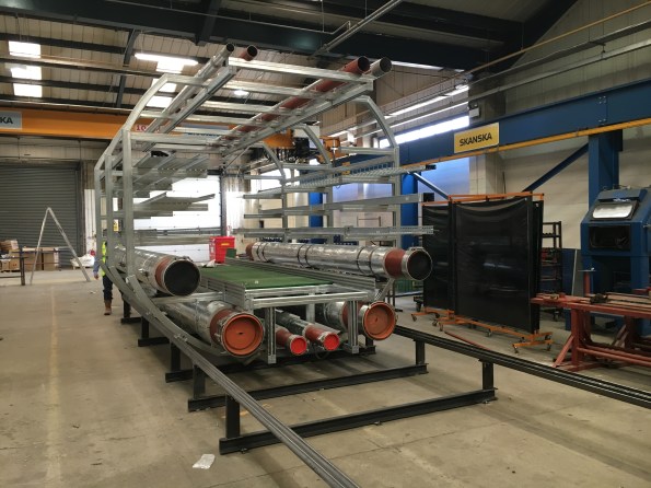
Yesterday I visited Skanska Fabrications in Slough where 22 pre-fabricated tunnel modules are being manufactured. These modules will be used to for chilled water, high grade hot water, low grade hot water, domestic water, low voltage, high voltage, data and fire alarms. Each module is 3.2m wide and 6m long and weighs 4000kg and to give an idea of the scale of these goliaths, the picture below shows one module and the lower large orange-capped pipes are 400mm in diameter – so not small!!
![IMG_0382[1].JPG](https://pewpetblog.com/wp-content/uploads/2016/06/img_03821.jpg?w=595)
The first tunnel module nearing completion
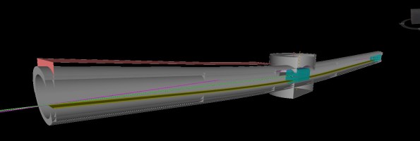
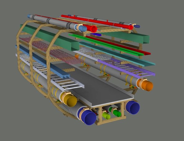
The BIM Model used to develop the installation method (note the centre shaft, winch cable lines and differing inclines)
These modules were designed using BIM and BIM also was used to simulate the modules being moved by a winch to ensure there was enough clearance in the tunnel for the winch cable and also to calculate the size of the walkway to ensure the winch cable could be ran through the centre of the installed modules in the latter stages of the installation. A picture of the BIM model showing the winch cable analysis is above. Since the modules were designed using BIM, every part of each module has its own asset code and a QR code sticker is placed on every pipe section, tray, bracket etc. These QR codes can be read by our iPads on site and they are linked to the BIM model using Naviswork BIM360 Field meaning that if I required any information about a component during installation all I have to do is scan the QR code with my iPad and I will be provided with design data, flow rates, mass, supplier and several other data sets. I have been very impressed with this system so far.
It is my responsibility to install these modules in the 132m, 4m wide tunnel and so I am regularly visiting the factory to check the quality of the finished product and identify any issues so changes can be made prior to delivery to site. One of the first issues that stood out to me was the lack of lifting points and winching points and so the fabricator is going to develop a suitable design solution and I will arrange a factory visit for the lifting Sub-Contractor to check the design and final fabrication.
The tunnel nearing completion
The second fabrication issue that became apparent during my visit was the use of corrugated kick-plates which prevent the floor panels from being lifted out, significantly hindering future maintenance. Again the fabricators are going to redesign these and opt for a flat kick-plate.
Another issue is whether or not the modules will slide down the 0.537 deg slope under their own weight. The Project Manager responsible for this design was adamant that they would slide as PTFE slip pads are used between the modules and the rails but I was confident that they will not and this debate has been going on for several weeks. Anyway rather than guessing I decided to use some GCSE physics to calculate whether or not it would slide. My calculation was that it would not and in fact it would need a 1.7kN force to get it moving. This for me was one of those moral courage moments as I did not want to blatantly challenge a senior PM but if it didn’t move, it would be my problem to resolve on site and the requirement to push or winch the first modules would fall outside of the package scope and would incur additional cost. So I was keen to mitigate this risk early to reduce costs and avoid any unnecessary delays.
So this short visit has confirmed to me the importance of off-site inspections and inspecting a physical product rather than purely relying on a BIM model.
I thought this post may induce some debate over the benefits of this pre-fab approach. The client and senior leadership team seem very happy with it but I am not convinced. The main issue with this design is that we have to wait until the tunnel is completed before installing the modules where as if we were using a traditional installation, we could be mounting brackets, trays and pipes directly behind the slip formwork as it moves along the tunnel, casting the secondary lining. Plus looking at sustainable development, these modules will be a challenge to remove when the product reaches the end of its life as the centre access shaft will be capped and backfilled. Also I think the module frames will make maintenance much more difficult. Thoughts?
On a personal note, I have got my aircraft flying again and so I am once again terrorising the skies above Essex and Hertfordshire. I would therefore recommend avoiding flights out of Stansted or Luton for the foreseeable future.
![IMG_0200[1]](https://i0.wp.com/pewpetblog.com/wp-content/uploads/2016/06/img_020012.jpg?w=294&h=220&ssl=1 "IMG_0200[1]")
![IMG_0358[1]](https://i0.wp.com/pewpetblog.com/wp-content/uploads/2016/06/img_03581.jpg?w=293&h=220&ssl=1 "IMG_0358[1]")
I want problems not solutions!
Not much to report on my site due to construction delays resulting in no on-site E&M activity and so my days are currently spent reviewing tender bids and checking designs. So instead of blogging about something interesting happening on site I thought I would write about a little ‘wrist slap’ I got the other day which for me highlighted a key difference of how we as Army Officers sometimes ‘do business’ compared to Engineers and Project Managers in industry. I hope this may serve as a warning to others or the Phase 1s.
Last week I was reviewing the mountings for three 11T chillers and calculated that they had a uniformly distributed load of 14kN/m^2 which exceeds the slabs design load of 9kN/m^2. Also these chillers are mounted in the centre of the slab and exert a maximum point load of 31kN which again exceeds the specified design loads.
Since we are under a management-only contact, the responsibility for the design of steelwork mounts or slab reinforcement lies firmly with the Principle Designers, in this case BDP. So I wrote an email to BDP explaining the problem and in good Army Officer fashion, I didn’t just point out an issue but also suggested 3 possible solutions that we in the office had been discussing based on the specification of the selected chillers which up to now the designer had no visibility of. So, a job well done thinks I and I move onto another task until the designer replies with a developed course of action.
Anyway, within a few hours I received an email back from a member of the project working for Skanska instructing me to not ‘suggest’ potential solutions in future correspondence to the designers. This is because the designer (who is getting a reputation for cutting corners and doing as little work as is possible within the confines of the contract) will likely read the email and just choose one of my suggested solutions without investigating it further or developing a detailed design as I had hoped. Furthermore the designer would likely list Skanska as being responsible for this design change which would ultimately result in Skanska unknowingly accepting a significant design risk. Oopps!
So from this I have learnt that although some of the methods we have developed in the Military are generally very useful and well received in industry, we still need to be careful as they may not always be the most appropriate and we cannot always assume that those around us will also act in a similar ‘good ole military fashion’.
