Archive
Modules Anyone?
The project I am working on is making extensive use of pre-fabricated modules and so I thought it might be of interest to the other E&Ms. Here is a diagram showing the major module units that have been designed for the two buildings and tunnel being constructed as part of the project.
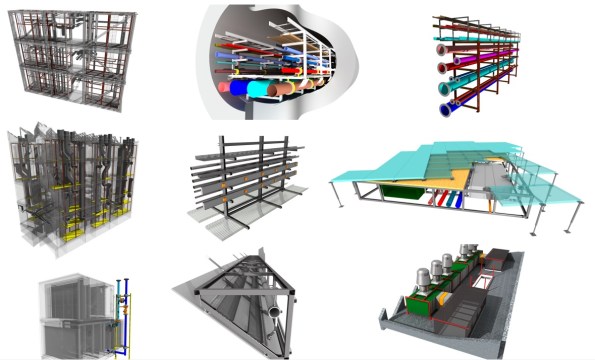
Figure 1 – BIM Model of 9 of the module units
Description
Top Left – Energy Centre Rises that connect to the tunnel modules
Top Centre – Tunnel Modules (3.5m Wide, 6m long and coupled together with a centre walkway)
Top Right – R&D Building Services Ring
Middle Left – R&D Risers (3 risers in total)
Middle Centre – Lab spine (medical gases, domestic services and 3 phase-busbars that can be tapped off anywhere in the labs)
Middle Right – Underfloor modules
Bottom Left – Cooling/heating Coils.
Bottom Centre – Sprinkler modules (600 of them concealed in the saw-tooth roof of the R&D centre)
Bottom Right – AHUs
Lab Spines
Of these modules, I think the lab spine modules may be of particular interest to the military engineer as recent operations have proven the necessity of rapidly deployable and easy to construct medical services. These modules would support this requirement very well and could provide a variety of services from medical gases and domestic services to power and data distribution.

Figure 2 – Showing the variety of medical services included
In order to install this spine system, each module is elevated and suspended from the ceiling and then the modules are braised together which also means that the level of craftsmanship required for installation is very low.

Figure 3 – The Lab Spine layout showing the tap-offs and outlets
This system is incredibly versatile and acts as a universal busbar where a tap-off can be placed anyway along the spine and the user can draw off 3-phase power, hot water, cold water, medical gases and compressed air.

Figure 4 – View of the medical gas outlets
In addition to providing services, the spine also acts as an open air cable tray, providing a tidy solution for internal wiring and data cabling.

Figure 5 – Electrical services are located at the rear with a busbar at the bottom and cable trays above
These modules are not due to be installed until April next year and so sadly I will not be involved in their installation and commissioning but I hope to be involved in the tendering and final specification as part of my phase two attachment.
R&D Build Project
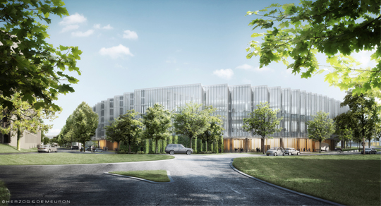
Figure 1 – The design for the R&D Building
Having now been on site for the grand total of two weeks, I thought it was time to post my first blog and explain the project to set the scene for future blogs.
PROJECT OUTLINE
The project I am working on is the construction of a 56,000m2 Research and Development (R&D) facility North of London. The build covers two sites, with a main R&D building to the North and an Energy Centre to the South with a public road dissecting the two sites. A 4m wide, 150m long, services tunnel runs under this road, connecting the R&D building to the Energy Centre to provide mechanical and electrical services and data. The road running through the site is an important ‘blue lights’ route for the emergency services and the South Site has a high speed railway running along its Western boundary – both of which create significant environmental challenges and places a number of constraints on the Project. Skanska Construction UK Ltd are the Principle Contractors for the Project.

Figure 2 – The Energy Centre
PROPOSED DESIGN
The R&D Building is a 4 storey reinforced-concrete building comprising a basement level and ground level accommodation, consisting of six glass boxes, supporting a two-floor disc. The disc contains two floor plates and has a staggered vertical façade and saw-tooth roof. Upon the roof there are six small external open plant rooms. The R&D building is still in the construction phase with the majority of the basement concrete pads still to be constructed although work has started on the ground floor with some of the Eastern concrete floor pads being poured.


Figure 3 – Construction of the R&D Building
The Energy Centre is a 3 storey steel frame building traditionally built and enclosed in cladding of different types. It has a lower basement area to only one part of the building and one side of the building is allocated to Facility Management and so includes a number of offices and control rooms. The building has a flat roof which will be used to house some mechanical plant including cooling towers and AHUs. Two large flues will run from the roof to the basement to provide an exhaust for the Cooling Towers, boilers, generators and combined heat and power (CHP) unit. The steel frame for the Energy Centre is still under construction. The tunnel connecting the R&D building to the Energy centre ‘broke through’ last week and so work is underway reinforcing and completing the tunnel walls.

Figure 4 – Construction of the Energy Centre
CONTRACTURAL ARRANGEMENTS
Due to the well-developed relationship between the Client and the Principal Contractor (Skanska UK), the project is being conducted under a cost plus JCT contract with the client retaining the design and ground risk. I am working for Skanska Rashleigh Weatherfoil (SRW) who are the Building Services arm of Skanska Construction UK Ltd. This means that Skanska UK sub-contracts the building services installation to SRW who in turn manage the building services projects and then contract the installation work out to sub-sub-contracts. The various mechanical and electrical supply and installation packages are conducted under fixed lump sum contracts.

Figure 5 – The services tunnel linking the Energy Centre to the main R&D Building
SO FAR SO GOOD……
As a project manager in the MEP (Mechanical, Electrical and Plumbing) Team for the Energy Centre, I will be involved in both the electrical and mechanical fit out of the Energy Centre and services tunnel which is due to start in Aug 16. Currently I am managing a package to plan, tender and contract out the off-loading, moving and placing of the various plant (boilers, generators, transformers, chillers, large pumpsets, CHP etc) and so I am getting plenty of exposure to the tendering and procurement process. This is proving to be a valuable first role as it means studying all of the technical drawings and developing an understanding of the wider M&E packages – all of which this package will support.
This project is very innovative and is utilising several interesting design features such as a 270m deep ground source heat pumps, a new revolutionary, highly-efficient, baffled cylindrical heating shunts (first time this technology has been used in the UK) and stainless steel rebar to name but a few; and so I already have a few TMR titles in the making!
Gary Jackson
