Archive
Covering your back or am I just being cynical?
I’ve now completed my handover of the London School of Hygiene and Tropical Medicine (LSHTM) steam replacement project. Bryden Wood Ltd (BWL) has completed the design, which has been approved by the client and is waiting with all the other tender documentation to be issued for the selection of the principal contractor. Except if I were a betting man I’d put a reasonable wager on that this project won’t be put out to tender anytime soon. Why?
As I’ve previously mentioned steam is currently generated at basement level and supplies autoclaves within the school, serves as a backup heat source for LSHTM and also feeds a district heating system (which is not utilised). What I’ve not gone into is the contractual relationship of this setup. LSHTM don’t own the steam generators, even though they are within their building. They’re owned and operated by an FM company called Cofely Ltd who use them to provide resilience to a district heating system and also sell steam back to LSHTM for use in the school’s autoclaves and backup heating. The brief BWL received from the client was to replace steam generation for the autoclaves and LSHTM’s backup heat source, not for the district heating system. We’ve done this. The client was going to formally / had already informally confirmed with Cofely that Cofely no longer required steam to the district heating system and that LSHTM would no longer be buying their steam from Cofely. What has become apparent is that this plan was based on conversation that had been conducted by LSHTM’s estates director, a man who has now jumped ship. This has left the LSHTM’s estates programme manager with no top cover. What if Cofley decide they do need a steam supply to their district heating system? BWL’s design will need a complete overhaul. Even if Cofley are still happy to lose the district heating system they will presumably want some form of financial compensation to offset the loss of income associated with no longer being able to sell LSHTM steam (although this will be offset by not having to maintain the steam generators). LSHTM’s team don’t appear to be clear on what their exact contractual position is with Cofley, so there’s a whole load of uncertainty to be resolved.
A new estate’s director has been appointed and has put all planned projects on hold until he as personally reviewed them. This should have seen the steam project being reviewed a couple of weeks ago; it hasn’t. I recently had a chat with the estates programme manager who told me that the review of the steam project was being put on hold as there a few large capital projects due to start and they were at risk of taking on too much at once. This could very realistically be the case or it could be that the programme manager doesn’t want to expose to the new director just how much of a mess the contractual position with Cofley is. The large projects serve as a great excuse to delay and get the house in order.
So what?
From my point of view this is a classic example of ensuring you conduct your stake holder analysis and identifying the critical factors for success. From BWL’s perspective they’ve been paid for the work that had been done, so there is no loss and LSHTM are offering BWL additional work (which was the main aim of this project).
Innovative Ventilation
Bryden Wood Limited is a multi-disciplinary consultancy. It’s brand is based on innovation off-site manufacture, which produce efficiency and quality for the client. This should probably be reflected in our offices. Recently we’ve had a new meeting room installed where some innovative approaches have been utilised to supply ventilation…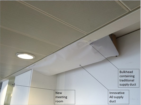
In other news George Garthwaite was born just under a month ago. I very nearly got to add midwifery to my competencies, but thankfully a professional arrived in the nick of time. Everyone is doing well. Thank you very much for the Giraffe and bibs from the Mess.

Phase 3 Concluding Blog
My time on phase 3 is drawing to a close (3 weeks to go) and phase 2 have now been on site for a while and are possibly starting to consider their options for phase 3. I thought it might be worthwhile blogging about finding a phase 3 placement.
I’ve been attached at a company called Bryden Wood Limited. Bryden Wood is a small consultancy with approximately 80 employees split across four offices (London, St Albans, St Petersberg and Singapore).
How did I find my placement?
I used contacts I made whilst on phase 2. Carillion’s M&E design manager at Battersea had worked in consultancies previously and used his contacts to get me an interview / informal chat at BWL. That chat was pretty pain free and was as much about me confirming that BWL could for fill my requirements. Other options that were open to me but that I didn’t follow up were working for Carillion’s consultants. I didn’t pursue that option as I felt there would be too much risk of being sucked into working on design associated with Battersea.
Advantages of working at Bryden Wood:
The advantage of working for a small company like Bryden Wood is that I don’t feel like a small cog in a huge unwieldly beast (which was often the case at Battersea). The projects I’ve been involved in have been relatively small in size, which means I’ve had a great deal of autonomy on them, which has been very useful for gaining experience. The company also doesn’t feel particularly corporate and has a family feel to it, which makes it a nice environment to work in.
Downside / Risk of working at Bryden Wood:
The main downside of working for a small company like Bryden Wood is that there is a bit more risk in terms of the amount of work available. We’ve had a few projects put on hold, which has led to contractors and permanent staff being laid off. This has led to the number of projects I could get involved with being reduced, that being said I’ve never been without work; although for my last two weeks it looks like I’ll be doing some pretty mundane CAD work.
Potential Opportunities
In summary I think my attachment at BWL has worked well. Although I’ve not covered as many projects as I thought I would do at the start of phase 3 I think I’ve covered enough – the proof will come in a few weeks at CPR. I still stand by my decision to go for a smallish firm. I’d recommend BWL to any M&Es looking for a placement in London or Hertfordshire. I’d be more than happy to make introductions if anyone wanted look at them for a possible phase 3 attachment.
The value of 3-D Modelling and record keeping.
The majority of my time on phase 3 has been focussed on working at the London School of Hygiene of Tropical Medicine (LSHTM). LSHTM’s building was opened in 1929 and has undergone several overhauls and extension over the last 80 odd years. This combined with the fact the keeping of record drawings seems to have been considered as an embuggerance as opposed to good practice made working out how I could modify their systems a bit more tricky than it needed to be.
If LSHTM were to be considered as left of arc, I have more recently been working on a project at the right of arc end of the spectrum; the re-modelling of Circle Reading Hospital which I have previously blogged on. The scope has now been expanded slightly. The client now wants to change the use of a waiting /reception area to a group activity (physio) room. This has implications with regards to the level of ventilation required to the space and the cooling load required. Although not contractually completed to a specific BIM level, Circle Reading was designed in Revit with the associated Navisworks models still in existence. This has allowed me to quickly interrogate the model via a desk top study to see what is supposed to be in the ceiling void and work out what space and services we have to play with. The client’s F&M team have also been very good at keeping records, so I have been able to interrogate the original main contractor’s commissioning results and compare them against the original design specification and schedules. From there it has been a case of applying the necessary calculations to work out what the new load is, confirming if the existing system has sufficient spare capacity and in what areas modifications need to be made to allow my proposal to work. Of course all this would have been possible without the information I was given, but it would have required hunting around the building for equipment details, getting airflow velocities and getting into ceiling voids to see what is actually there. The use of 3-D modelling and good record keeping has allowed me to meet the client’s intent of getting a proposal out cheaply and quickly. There will be significant caveats applied to my design note as I’ve not confirmed my design start point on site; however, the client is aware of this risk and happy to proceed.
Circle Reading Remodelling
The most recent work strand I’ve been involved with at BWL is the re-modelling of a private hospital in Reading. The hospital is owned and run by Circle who have a long term relationship with Bryden Wood Ltd (BWL). The requirement to re-model is based on Circle wanting to go into a joint venture with a German health care provide called Vamed. The plan is to hand two of the four floors of the existing hospital over to Vamed. This requires a number of rooms on the second floor to be changed. The client’s drivers are cost and time. Initially BWL priced the job at £90K for an architectural and M&E design role. The client currently doesn’t have a formal agreement in place with Vamed, so the real driver is to get the work done in order to seize a potential opportunity whilst spending as little cash as possible. This has led to a reduction in BWLs fee to £10K, which means BWL’s outputs are limited to a concept design which will be taken forward by the main contractor. I can understand the financial pressures the client is under, but it seems a little odd that the first interaction in a future strategic relationship is being done on a shoe string budget.
From an M&E perspective there are 2 engineers working on this project (1 electrical and 1 Mechanical). The limited budget means that this work needs to be turned around quickly, which is great for me as it’s another project under my belt for CPR.
What has my role been:
As the sole mechanical engineer working on the project I’ve been responsible for checking the implications of the changes of use on the mechanical system. This has entailed:
- Producing room data sheets for each area to define the environmental standards that need to be met (ventilation rates, temperature, acoustics, etc.)
- Using the data from the room datasheets to calculate loads for each area (cooling, heating, ventilation, domestic cold water, domestic hot water)
- Identify the best possible way to meet the new demands. As an example active chilled beams are utilised to provide comfort heating and cooling, where possible these have been retained, but where loads are too great or not close to the current distribution network other solutions have been provided.
- The impact of these solutions have then been confirmed: basically checking pressure drops in pipework and ductwork and making alterations where required.
- Engaging with my electrical and architectural colleagues to ensure that our designs are co-ordinate.
- This has then been pulled together into a scope of works, including mark-ups of existing schematics and schedules of new equipment so that the contractor can price the job and take the design forward.
All in all a good little project that has given me some solid B and D competencies. It’s probably worth noting that I found the calculations involved in conducting this work to be much simpler than those conduction for phase 1: phase 1 more than prepares you for the technical aspects of phase 3.
Wasted work
In my last blog I mentioned that there had been a bit of a question 4 moment with regards to steam at LSHTM. This was based around the client asking me to explore other opportunities with regards to steam distribution.
In mid-March I took isometric drawings produced on Revit to the client for approval on the distribution strategy. Prior to conducting the work in Revit to produce these drawings I had discussed the proposed route with the Project Manager (PM) within the LSHTM estate’s team. The route I was proposing was based on taking steam from one side of the building where it was being generated at high level to where it was required on the other side of the building via an external route. This was because I had been briefed to minimise the amount of disruption to the building which would be fully operational during the works. I discussed this route with LSHTM’s PM and even took him to look at it with a possible contractor for comment on the buildability of my proposal. Having gained buy in of the client I proceeded to continue with the work and produce the required drawings in Revit, which took me approximately 1 week. What I failed to do was quickly mark-up a drawing by hand and send it to the client for them to approve formally. It was then at the meeting in March that a more senior member of the client team expressed disapproval with my proposal and asked me to look at another option. This is frustrating on a personal point of view as it is duplicating my work on the same experience and there is little competency experience to be gained from producing drawings in Revit (although being able to use Revit can go towards my A competency). It was also a missed opportunity from a BWL point of view. Because BWL are attempting to develop a relationship with LSHTM there was no resistance to LSHTM’s suggestion from my director. Probably in part because with me doing the work there is limited cost to BWL. If I had sent a mark-up which had been signed off by the client there is more chance that my time wouldn’t have been wasted in that the desire to explore other options could have been looked at prior to me doing the work in Revit, or if it had been approved I would have had an audit trail to fall back on. I could have more rigorously demonstrated that I had developed the design in good faith and that the proposal being made to consider another route was effectively a variation and required an additional fee. Whether my director would have wanted to do this is questionable, but it would have at least given BWL the option and has certainly taught me valuable lesson.
LSHTM Condensate Recovery Analysis
LSHTM Steam System:
My involvement in the London School of Hygiene and Tropical Medicine (LSHTM) steam replacement continues. I’d hoped that the design would be complete by now and that I’d be moving on to something else but there’s been a slight question 4 moment. But I’ll come onto that in another blog.
Intro
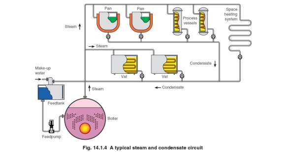
As previously mentioned steam systems generally consist of steam mains (flow) and condensate (return) pipes. Condensate is transferred from the steam main to the condensate pipework by means of a steam trapping station. The system we are putting in is mainly to supply autoclaves (sterlisers), but is also a backup supply for a heat exchanger if the normal LTHW boiler falls over. When the steam gets to the autoclaves it will transfer to condensate like in any load, except that in autoclaves the condensate is then contaminated and cannot be returned to the steam generator. This means that the only condensate available for recovery is from losses in pipework during running and warm up and cool down. Bryden Wood’s proposal which won them the job was to generate steam at high level (fourth floor), collect condensate and send it under gravity to low level (basement) and pump condensate back up to the generators in a separate pipe.
I’ve calculated that on a normal day LSHTM will use 10m3 of water for steam, 3% of this usage is due to running losses and is potentially recoverable the rest goes down the drain via autoclaves. What is less clear is what should be done with the condensate that is recoverable. Was the original Bryden Wood proposal correct? I was originally told that we were recovering condensate as it is best practice and the most cost effective method. This blog will cover some COA analysis on 3 possible options to deal with the condensate being recovered:
COA1:
Stick to the plan as described in the Bryden Wood proposal. This will require the installation of a condensate recovery unit in the basement. This is basically a tank vented to atmosphere which collects condensate that falls under gravity and allows it be pumped back up the building by means of an electrical pump. The tank is vented to atmosphere to minimise the possibility of cavitation occurring on the pump due to a sudden pressure drop in a liquid at high temperature. This plan is in line with common thinking associated with steam operation: always recover condensate. This is because by reusing condensate you don’t have to heat feed water up from 10 oC so energy is saved; you don’t have to pay for more water and also to treat more water. Although as highlighted above the system being put in place will only have 3% of the total steam used available for recovery. This leads to a saving of £1.81 a day by having a condensate recovery unit or a payback period of 7.5 to 17 years, depending on the type of condensate recovery unit, not including installation and running costs. Doesn’t seem worth it. However this does not factor in the back up heat exchanger. Although never / rarely used, if this system were to be used it would generated up to 600kg / hour of condensate. This then starts to have a more significant cost saving of £3.62 per hour. Although this saving is unlikely to impact the payback period as the heat exchanger would only be required to cover outages which would unlikely be more than a couple of days a year on average if at all. It still doesn’t seem cost effective to utilise. However one of the environmental requirements of utilising steam is that any water discharged to the foul drain cannot be greater than 43 oC. Condensate at atmospheric pressure will be just below 100 oC. If a condensate recovery unit were not used then another means of getting condensate away from the heat exchanger would be required or to cool it before going into the drain.
Strength:
- Provides a solution that is in line with industry practice.
- Allows system to drain fully on start-up and cool down avoiding water hammer.
- Does not result in hot condensate being discharged into the drain.
Weakness:
- Returning condensate does not offer a huge cost saving.
- A condensate recovery unit will take up space in the basement.
- An additional piece of equipment is required which will require maintenance.
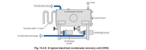
Typical condensate recovery unit.
COA2:
Rather than collecting condensate via gravity just put it into the existing drainage near to the steam traps where it is collected. This drainage is designed to deal with hot liquid from the autoclaves and should therefore be cooled by the time it gets to the foul drain. This goes against best practice, but is based on the fact that the assumption there is a cost saving of recovering condensate is flawed in this situation. Potential condensate from the heat exchanger would still need to be dealt with but this could be achieved by using a self-contained pump trapping station which would fit on the existing heat exchanger skid and utilise steam power to push condensate back up to high level. Unfortunately getting to the existing drains from the steam traps is easier said than done and will create a huge amount of disruption not to mention the requirements to install vent lines everywhere; when condensate that was at 6 bar g passes to atmosphere a large portion of it will want to flash to steam, therefore vent lines would be required to avoid pushing steam into the drain. Therefore due to installation issues this option was not considered any further.
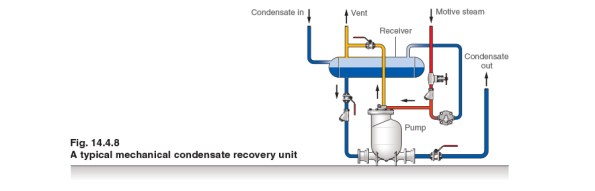
Typical steam powered condensate pump.
COA3:
Same as COA2 but rather than putting the condensate from the traps to drain utilise the pressure difference across a steam trap (6 bar on steam side, atmosphere on condensate side) to push the steam back up the building to the steam generators. The lowest steam trap is 16 m below the generators, so allowing for backpressure and friction losses there should be a net pressure of 4 bar to push the condensate back to the generators. However when the system is turned off and cools down the pressure across the traps will drop until there is not a net pressure difference. At this point condensate will not be recovered and will fall back to the non-return valves on the traps. When the system is brought back on the condensate in the pipes will rattle back to the steam plant potentially causing noise and damage as it goes.
Strength:
- Recovers condensate in line with industry practice.
- Minimises the amount of equipment in the basement.
- No running costs associated with an electrical pump.
Weakness / Threat:
- Water hammer and noise on start up.
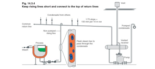
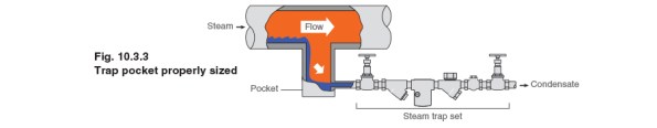
The left hand side of this figure shows a steam trap at the bottom of a process being utilised to lift condensate up to a common return line.
For this reason I’ve decided to stick with the original plan. This led me to question whether the exercise had been worthwhile. I believe it was. Although I’m not changing the scheme it’s always good to question what is put in front of you rather than accepting it blindly. Secondly I believe the reasons that I have come up with for sticking to COA1 are slightly different to the reasons why it was selected in the first place: I am selecting it based on it being a solution that minimises problems with respect to installation and running, whilst the original logic was that it was the most cost effective solution.
CPD
One of the competencies I was aware that I was weak on prior to turning up at phase 3 was E4 – CPD. It’s not that I hadn’t done any CPD during phase 2; I’d done a reasonable amount through blogging, conducting Carillion online training packages, weekly informal educational periods with my mentor and reading journals. What I didn’t feel I’d done well enough was attend formal events; simply I found the pace of life during phase 2 too hectic to achieve what I wanted to.
During the three months I have been at phase 3 I have already managed to attend 4 formal CPD events. And have got more pencilled in, which I feel will be more than enough to cover off my requirements for professional review. The next stage will be to make sure they are all formally recorded. Although I am finding phase 3 a lot more stable than phase 2, I’m still finding it difficult to attend evening CPD events. I’ve found trying to strike the balance of doing CPD in the evening, army evening work, family life and social commitments difficult. Time is my critical resource, things slip and often evening CPD events have to drop off the radar. I am lucky that my current employer if fully supportive and arranges for companies to come in and deliver CPD on a regular basis during the day which is helping, however, a resource that I haven’t utilised enough previously and am starting to do more of are webinars. Many of these webinars are accredited to institutions and there produce certificates that making recording them formally even easier. A few that I’ve come across so far are:
Colt – Ventilation, smoke management
BSRIA – various
https://www.bsria.co.uk/information-membership/events/webinars/
British Safety Council – Upcoming event with regards to environmental standards
https://www.britsafe.org/events/2016-webinars
The Building Built By Gurkhas
This blog doesn’t focus on my experiences, but is a quick summary of other work being conducted by BWL. If you’re interested in pre-fabrication of or Gurkhas it may be worth a read. The work that I’m going to quickly talk about is the design, manufacture and construction of a pharmaceutical factory in a box. This has recently been written about in February’s issue of the Construction Manager. I don’t have a link, but I do have a scanned copy of the article if anyone would like it.
There is a growing demand for pharmaceuticals in the developing world. Previously issues surrounding the supply chain and skilled workers in developing countries had made constructing high-specification buildings such as pharmaceuticals factories difficult. Therefore GSK as the client and BWL as the consultant have come up with a system that has allowed a facility to be built at 30% of the cost of a traditional approach and in four weeks rather than 12 using a team of just 8 ex-Gurkhas.
The factory comes pre-packaged in iso-containers and is packed in such a way that the first item you remove is the first item that is needed. The building looks to be a steel portal frame with the factory then sitting inside this structure. There’s no mention in the article about pre-ceding ground work requirement, but how difficult is that? The factory includes details like the roof of the frame coming flat and then being able to pivot about the apex and be locked into position to avoid working at height. Likewise the factory internal roof is constructed at low level, services added and then elevated to the appropriate height using block and tackle. Connections between components are made with simple bolted connects that are colour coded to ensure the correct bits are put together.
All in all it looks very innovative project that has wider reaching applications. The significant element of doubt I have about this is that it was completed by Gurkhas. When people have discussed this in the office with me they’ve implied BWL and GSK used Gurkhas because they’re representative of the workforce that you might find overseas. Nobody seemed to be aware of the rigorous selection process that is required to become a Gurkha and therefore your probably dealing with someone who is brighter than the average. Also the article makes reference to the fact the workforce had some plumbing, electrical and decorating experience. Not sure if that means they were ex-Gurkha Engineers or not.

A screen shot from the simulated build sequence showing trusses being moved into position.
London School of Hygiene and Tropical Medicine Update
As previously mentioned one of the projects I am involved with at Bryden Wood Limited (BWL) is the replacement of steam plant at the London School of Hygiene and Tropical Medicine (LSHTM). This blog is a long overdue update on the project, which aims to give background information and highlight what I’ve been doing.
The project
The LSHTM currently has two steam generators that are sized to produce 1300kg /hr of steam at 10 Bar g (g denotes gauge pressure). Steam within the building is mainly used for autoclaves (units you put kit in for sterilisation) and a couple of air handling units (AHUs) although the current generators are also linked to a district heating system and provide redundancy for an element of the school’s heating system. The generators are located in a sub-basement and distribute steam up two risers to serve the loads in the building. The LSHTM was originally shaped like a capital A. Extensions to the building have seen the two hollow sections within the building filled in. This is leading to insufficient ventilation reaching the plant room where the steam generators are, resulting in the building overheating. Analysis of the use of steam within the building has identified that it is no longer required to supply the district heating system and will only be used as a back-up heating supply in extremis. Therefore maximum steam demand is 520 kg /hr.
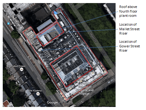
Aerial view of LSHTM. The red line demotes the outline of the building which used to form a capital A shape. The two hollow sections of the building have now been filled in.
The client, LSHTM, therefore wishes to install two new, appropriately sized boilers at fourth floor level and take steam back down the building to serve various loads. The existing system will stay in use and only be stripped out once the new system is fully online. This will require a period of gradual handover from systems as individual loads are brought online. The project is valued at £1M and the consultancy fee is a fairly small £50K.
The BWL team looking at this project is 3 strong; a director who effectively brought the job to BWL when he moved company, myself as the mechanical lead and an electrical engineer. The project is mainly mechanical in nature and the director is keen to take a hands-off approach, so I’ve essentially got a huge degree of responsibility and autonomy on the project which is great.
Steam
Before I go any further it’s probably worth explaining a bit about steam, although I won’t fully explain all the concepts this will end up like War & Peace. The following link is very useful and informative if you get involved with steam design at all or want more information:
http://www.spiraxsarco.com/Resources/Pages/steam-engineering-tutorials.aspx
In normal mechanical systems it is usual to see a flow and return pipe. This is the case when dealing with steam except that the flow pipe contains your steam, which is dry saturated steam (steam that has had energy added to it so that it is completely dry) and the return contains something called condensate. Condensate is generated when the dry steam is subject to a change that allows it to change state to a wet steam of liquid. This change in state can either be caused by a drop in pressure or temperature. The change in state can be deliberate – the steam is being used in a processs e.g. through a heat exchanger or unwanted, e.g steam running along a pipe cools and condensate is generated due to the loss in energy. What we don’t want to happen is for condensate to build up in steam lines (impacts the performance of heat exchanges, is corrosive and can lead to water hammer damage), therefore condensate is removed using something called a steam trap. We also don’t want to waster condensate if possible as it still has energy within it which we can reuse at the boiler / generator and is valuable in that water going into a boiler needs to be treated. Reducing the amount of new water required by recirculating condensate reduces costs massively.
What have I done to date?
I’ve surveyed the site and produced a basic REVIT model of the plant room that we need to put the new boilers. In conducting my surveys I’ve also identified that one of the AHUs being served by steam isn’t utilising the steam (valves isolated and pipes cold), I’ve since spoken to the facilities manager who has confirmed this has been the case for two years. This has allowed me to removed the AHUs from the steam load profile a saving that allows me to drop down a model size on the boiler and save the project up to £50k – not bad for just having a walk around. I’ve just pulled together and submitted a Pre-Qualification Questionnaire and mini-tender document for the purchase of the steam boilers which goes a long way to filling the short falls in my C competencies from phase 2. Next stage is to move onto a bit more detailed design and start sizing pipes.
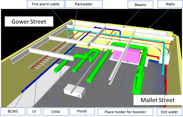
Basic REVIT model exported to NAVISWORKS to show the constraints within the fourth floor plant room.
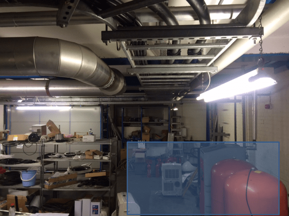
View within the fourth floor plant room where the new steam plant will go (denoted by the blue square).

View within one of the existing risers. This is the better set out of the two, the other looks like someone has just thrown pipes and wires in. There appears to have been plenty of expansion over the years but not stripping out. There are also no as built drawings or schematics, which when services are incorrectly labelled makes coming up with a plan interesting.
