Archive
Dancing about a bit
Appreciate there’s been a bit of a deluge of blogging lately but something came up in my office that I thought was interesting. Also apologies for no pretty pictures – I haven’t been able to get hold of anything relevant yet. You may or may not have read in the news recently about a magnitude 7.7 earthquake that hit the Caribbean yesterday. This was quite a large earthquake in a region that has a risk of seismic events due to the North American and Caribbean plate boundary close to Cuba.
Although Sir Robert McAlpine concentrate their construction operations in the UK they also ‘randomly’ have projects in the Cayman Islands for which MDG do some design work. The Cayman Islands are in the Caribbean region south of Cuba close to the epicentre of this recent earthquake. In the office this morning our team had a call to say that a self-supporting tower crane (on pile foundations) on a Cayman site was ‘dancing about a bit’ yesterday. Secondly a sink hole appeared just over a metre away from the foundations of a mobile tower crane (with ballast foundation). At this time we don’t have a lot more additional information other than there were no injuries and the cranes appear to be still standing. The sink hole appeared in an area of limestone and so far no instrument has been able to determine its depth. Whether there are other voids in the limestone is unknown as I don’t think this was picked up in the GI.
It seems that the crane foundations produced by MDG were designed for tropical weather conditions including hurricanes but not for the seismic conditions. The original brief from site did not mention a seismic requirement but I think it would be reasonable for designers to take this into account. I think due to a lack of experience in this area in the UK it wasn’t considered. The problem facing us now as a result is to determine if the cranes can still be used and a possible redesign of the foundations. Furthermore there is a large risk of foundation failure near the sink hole. Whist the crane is still standing, additional loads either from wind or during deconstruction could undermine the weakened foundations. Clearly there is a cost and time impact to the project as a result. Particularly with addressing the sink hole problem which may require significant amounts of concrete to infill.
Does anyone have any experience with seismic and/or sink hole problems? How do you account for large voids in the rock – I imagine desktop study with GPR might be able to pick this up? I can see if we’re deployed anywhere with seismic activity as PQEs this may be something we have to consider and design for. There is guidance in EC8 for seismic design but potentially other more local codes based on experience might be more applicable (in this example US design codes might be more suitable).
TLDR:
- If you end up doing design work on sites outside of the UK don’t forget to at least consider seismic risks.
- How do you mitigate against large voids in rock during design and how do you resolve a sink hole issue?
- Any suggestions on foundation design for cranes against seismic loads?
- Sorry no pictures yet.
- Yes there is a whole load of other things that come out of this like who holds the risk etc but this blog is already long enough.
Temporary Works Tour: 1-5 Grosvenor Place
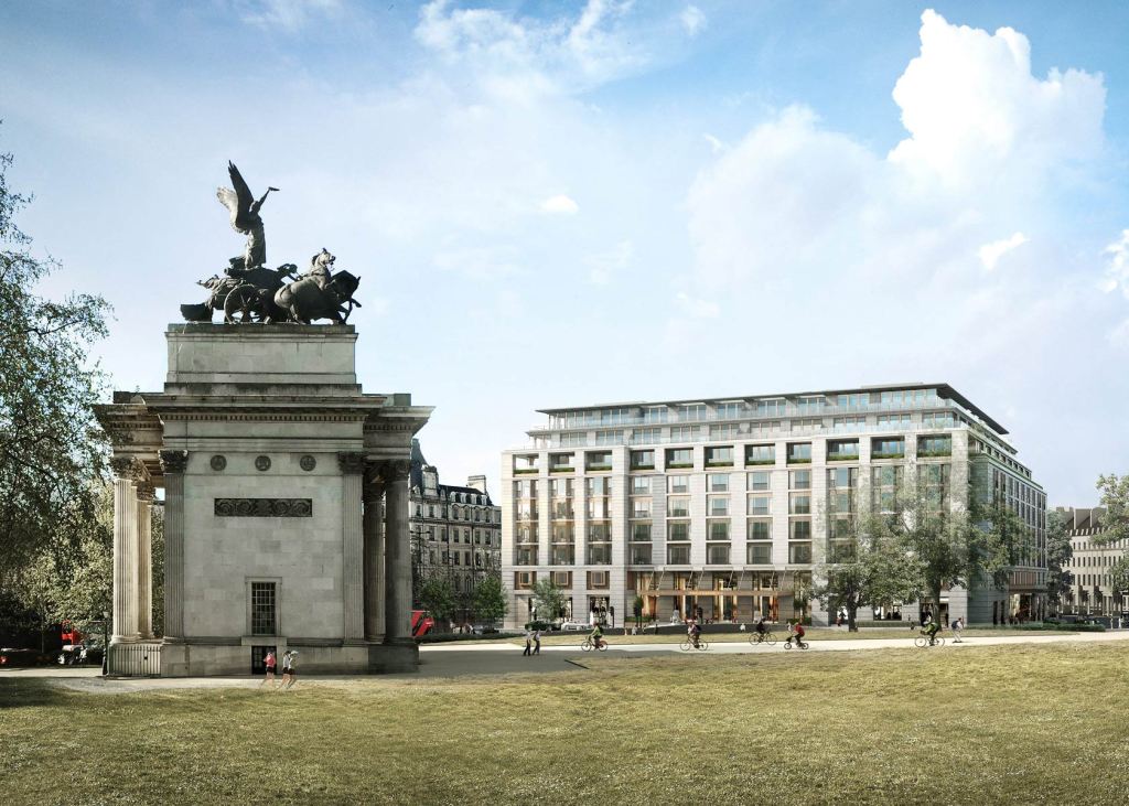
I recently visited a project in London where Sir Robert McAlpine Design Group are the temporary works lead. The project is to build a new hotel/apartment building near Hyde Park at 1-5 Grosvenor Place for Hong Kong and Shanghai Hotels. The building comprises 9 floors above ground and four to five basement levels below. As the basement construction period is significant due to the complex below ground structures, and the volume of material to be excavated and removed from the basement, the method of construction has been ‘top down’. This allows for the basement to be excavated and constructed concurrently with the superstructure construction and fit-out above, with savings to the programme. The building comprises four reinforced concrete ‘cores’ in each quadrant of the building which provide the main vertical access with a central courtyard in the centre. The central courtyard is currently used as the access for plant and material to the basement levels during construction, but will be covered by a garden on completion. The main structure has been completed with the first floors now being clad. The last two floors of the basement are currently being excavated down to approximately 20m below ground level.
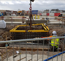
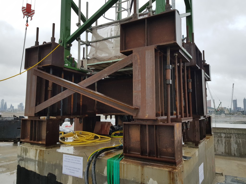
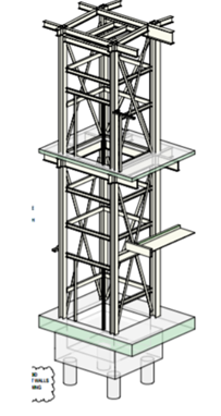
The temporary works on this project have been significant and I thought I would show the extent of them here. At each core of the building a crane has been placed on the roof. Placing cranes on the cores allows the building to be substantially completed and made watertight without having a void through the building for the tower crane mast. This has required a temporary works solution to provide a base to fix the crane. The supporting concrete core has been designed and enhanced to withstand the tensile stresses caused by the crane which has required bursting steel reinforcement. Note also the long post stressed threaded connections which are required to take the tensile stresses of the crane.
The site itself is very restrictive with very limited space for site offices. The solution has been to construct offices cantilevering out over the adjacent carriageway with a steel frame to support the offices above. To limit the loading on the pavement on which it is founded, a reinforced concrete raft has been cast over the pavement. Access positions have been required at any existing manhole or service cover locations. Further resistance to overturning has been provided by casting holding down bolts into existing grouted or concrete filled vaults below. The limited space has also required a solution for site traffic. This has been overcome by constructing a temporary steel structure to support a ramp and bridge through the courtyard of the building.
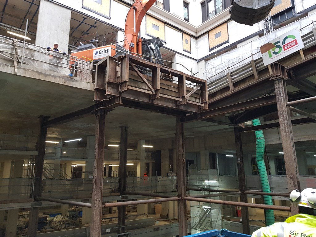
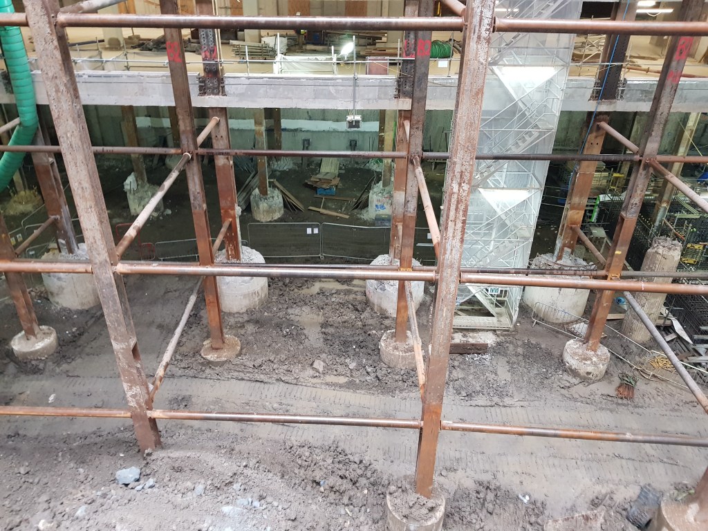
The steel structure is supported by large plunge columns that will eventually be removed and cut at pile cap level (see columns highlighted in green in the drawing below). The ramp and bridge allow site traffic to enter one side of the building and exit the other. A telescopic clamshell bucket shown in the image above is able to extract the spoil from the basement levels below and load it onto trucks passing over the temporary road structure.
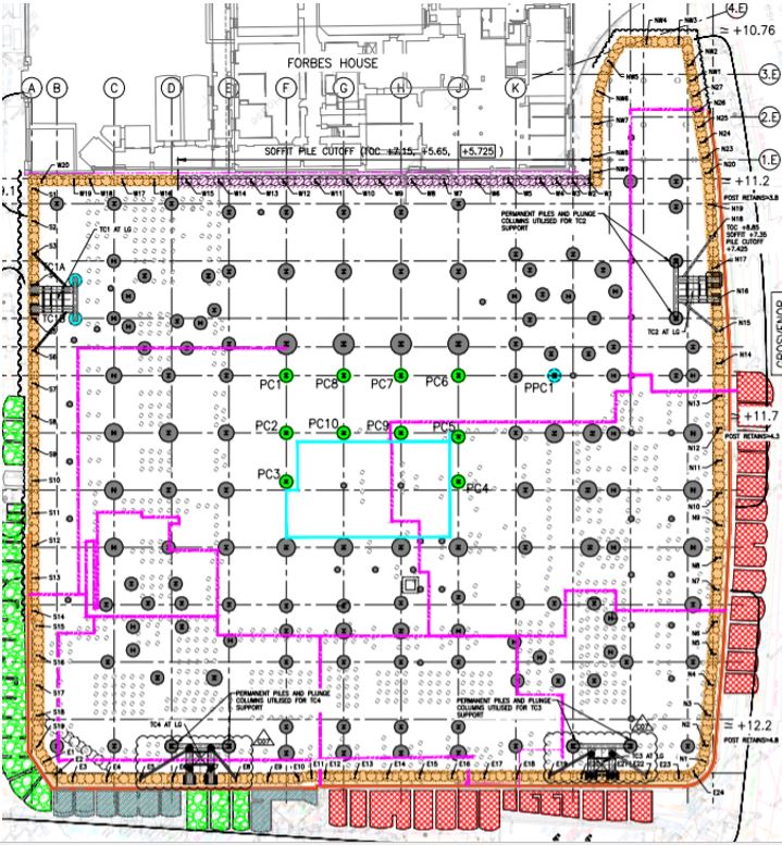
At basement level 1.2m diameter secant piles have been installed around the whole perimeter of the site (orange above). In particular propping has been required to strengthen the piling on the west end of the site where another building abuts the site closely (purple line above). This has been to limit the deflection of the secant piles and therefore limit the effects on the adjacent structure. Inclinometers have been installed down the length of these piles to monitor any significant deflection.
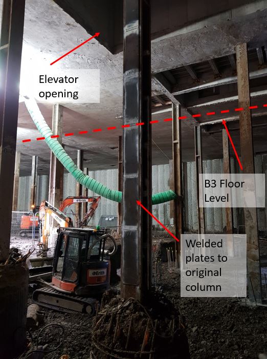
The basement is currently being excavated over the final two floors. This has been in order to enable large sized plant to operate and to allow removal of adequate volumes of clay per shift. Originally the design of the building only included three basement floors as planning permission for a fourth had not been granted during the design phase. However, later during construction a fourth basement floor was approved. This caused an issue with some of the existing columns that had already been installed. They would be too slender to take the loads from above in the temporary state before basement level 3 had been constructed. The increase in effective length between B2 and B4 level meant that some of the columns would need to be modified. In the image below shows where additional plates have been welded to the flanges of the columns to make them stockier and reduce their slenderness ratio.
The columns at higher level were originally to be encased in reinforced concrete. However, this has recently changed as the client now wants a masonry finish to the columns. This means that the cross sectional area of the columns are reduced, thus a reduction in the second moment of area. My involvement with this project so far has been to evaluate whether the columns are able to still take the axial loads without this reinforced concrete encasement.
This demonstrates the significant amount of temporary works involved in a project of this size, especially in a congested site like London. This offers some excellent opportunities for an engineer to get experience on a wide variety of engineering challenges.
Phase 3 – Total Recall
I have recently moved from Gatwick Airport to start work at Sir Robert McAlpine Design Group in their Temporary Works team. I’m still in the first weeks here but have already been given quite a few tasks to work on. It’s certainly been a challenge to recall the lectures and read my notes from phase 1 and apply them to practical examples! I thought I would share some initial observations early days.
Some of the tasks I have done already include designing a concrete lintel for an opening including props to enable the lintel’s installation. I have also done buckling checks on plunge columns (not strictly temp works…) which has had me looking over some of the worked examples and exercises we did in phase 1. In particular have found that using the IStructE Eurocode guides and just asking around the office has been helpful. It seems that the design team here prefer to do a lot of design by hand on calc paper almost exactly the way we have been taught in phase 1. The team also use quite a bewildering number of software programmes to check the calcs. However, Robot and MasterSeries seem to be the most useful. Robot in particular for frame, slab and plate analysis, MasterSeries for connections and capacity of steel members. I have also found that BeamPal is quite useful for doing simple bending moment and shear force checks of beams.
For those about to go onto phase 2 and then phase 3 at the end of the year I hope this shows that what we learn is put into practical use in industry. Also it might prove useful for future students to gain a working understanding of software they use.
Finding the ‘G’ spot – High Pressure Dilatometer
I’ve been recently managing ground investigation works at a car park that will become a temporary construction site for four large steel frame modules (Approx. 50x50m). The GI is for the temporary foundations which will support these modules. The cores that have been found on site so far have revealed Weald Clay Mudstone at the depth of the proposed foundations. Recently I observed the use of a pre-bored High Pressure Dilatometer (HPD) which I had not heard of before. I thought this might be useful to explain a bit further. It’s an unusual but accurate method of finding horizontal soil strain ‘ε’ and shear modulus (G) in-situ instead of laboratory triaxial tests. It’s used much more commonly in France and other parts of europe but I’ve been told it is increasingly being used in the UK. It was developed from the Ménard pressuremeter, which is still used but is less accurate. It can only really be used in fine grain soils and most rocks, though problems are encountered in limestone where there’s lots of flint. The device isn’t useful in coarse grain material due to the low plasticity of the soil giving inaccurate results. It works by placing a cylinder at a certain depth with a membrane surround (see image below). The membrane inflates to apply pressure against the soil, where a number of sensor probes measure the pressure of the soil. This pressure is plotted onto a graph against the length of membrane expansion.

It comes in 3 different types:
- Self-Boring – Has the advantage of being more accurate as the dilatometer fits the hole much better and there is less disturbance of the soil, providing more accurate results. Not viable where there are layers of coarse grained material that can disturb the borehole or where rock is encountered.
- Push type – Similar to self-bored, but the sensor is driven into the ground. Has similar advantages but is limited to soft fine grained material such as clays. This can raise the stress of the surrounding soil, limiting the data you can get from this method. It is however much quicker.
- Pre-bored – A borehole is made to the appropriate depth and a dilatometer inserted into the pre-formed hole. The main advantage of this is that it is more versatile and can be used in a number of different type of soils. Best used in rock and stiff clays. Cores can also be taken during boring enabling lab testing of samples. Less accurate due to soil disturbance during boring.
A graph of average readings from the car park soil can be seen below showing cavity pressure against cavity strain. You will notice that there are a number of loops on the graph not too dissimilar to the stress/strain curve. The HPD operator expands the membrane until the pressure begins to level, and then releases some of the pressure, allowing for the soil to recover. The pressure is then reapplied causing an ‘elastic rebound’. This is usually done three times to give a spread of results. As I understand it is the average rate of this elastic rebound that can be interpreted to find ‘G’. The test is continued up to a point where the pressure begins to level off. It is not so easy to see in this image, but the individual sensor results show a gradual levelling off. I was told by the operator that they usually stop the test at this point as there is a risk of membrane rupture. As each of these cost about £80k this is understandable!

I have been told there are relatively few GI specialists in the UK who can carry out this kind of test and even fewer who are certified to interpret the results. That said it seems this is a much more accurate way of finding undrained soil properties from in-situ testing against more empirical methods such as soil classification properties against previous data. It may be particularly useful on sites where there is little empirical evidence. It is also more accurate than triaxial testing as the soil is not disturbed significantly. The HPD is likely useful for projects where a high degree of accuracy is required from the GI to build substantial foundations reducing the risk associated with the ground. This said I think that the HPD might not have been required on the this site as the foundations are temporary: a less costly triaxial test may have sufficed. I would be interested to know what other opinions might be.
Other information on soil properties can also be derived from these results such as the coefficient of uniformity (Cu), though for brevity this is not included above. Further reading can be found in Craig’s Soil Mechanics 8th Ed p240-8
H&S File – to be or not to be?
A relatively quick update from Gatwick: The new Pier being built for the large A380 aircraft is approaching the end of the primary steelwork installation. Prefab passenger bridges connecting the building to the rest of the terminal have also craned into place. It is during this installation a fairly serious H&S incident was observed (see pic below). This shows a worker underneath a suspended passenger bridge frame. Under LOLER regs states there should be ‘a secondary means to support the load’ which clearly isn’t really fulfilled by the forklift. If the frame had been rested on trestles or props the risk could have been minimised. In short if one of the slings fail then there is nothing to stop the load injuring the worker. Clearly the worker was immediately informed of this and a near miss raised.

I have also been the client lead for some GI works at other site at the airport in preparation for ground works (aircraft pavement replacement and pile foundations) for the Pier 6 extension main build. These small packages of works have been separately contracted out to framework contractors who are well established at Gatwick. At one site, an aircraft stand, the GI involved concrete core sampling and in-situ testing of the subbase layer with a DCP. The GI works are now complete but the principal contractor seems to think that a H&S file is required. Firstly I’m not sure why they are raising this as it is prepared by the principal designer. Under CDM a H&S file is required where there is more than one contractor involved. There were two contractors involved on the works: the principal contractor (who also cored the PQ concrete to reach the subbase) and a subcontractor who completed the sampling and testing. However, I’m still not clear if a H&S file is needed in this instance. The coreholes were reinstated with a bentonite solution and I can’t see how there would be residual risks, as-builts (maybe corehole locations?) or maintenance requirements to document?
Clearly a H&S file will be delivered as part of the overall Pier 6 project by the principal designer, so this package of works would form part of that. The GI report would be delivered as part of the Pre-Construction Information for the groundworks contractor.
Looking forward I will be getting involved with the ground works contract for the main Pier 6 extension.
Childhood dream made reality – Lego meets construction
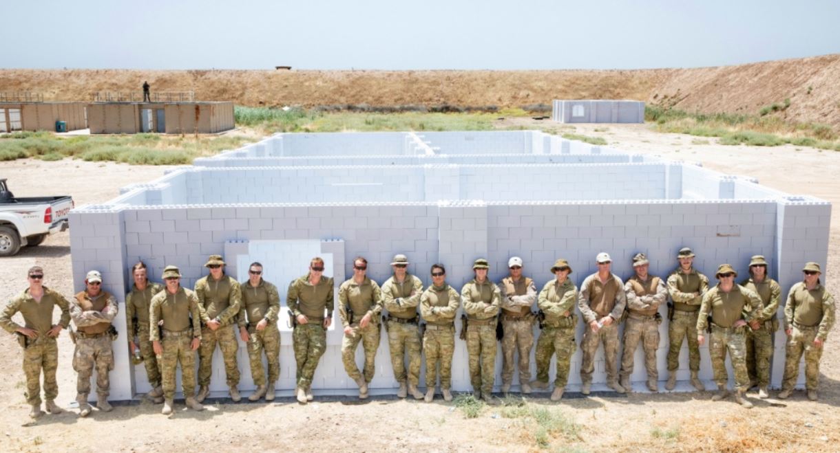
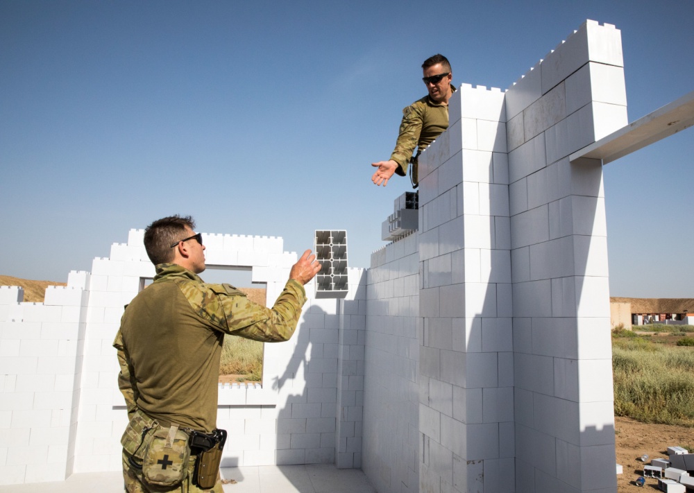
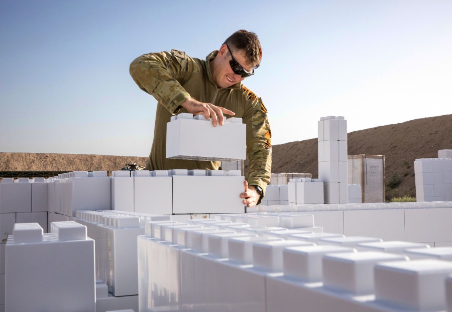
Whilst doing a bit of additional research for my CI paper presentation I came across a recent interesting news article. It seems that you can actually construct buildings out of giant plastic lego blocks! The pictures below show an urban training area being constructed at Camp Taji, Iraq by an Australian and New Zealand task group (news article here – 13 June 2019). The buildings were made using a system devised by a company called Everblock (official site here). The blocks claim to be durable and reusable which makes them potentially of interest to military construction. The blocks are also lightweight meaning faster construction, less operator fatigue and potentially less risk of lifting injuries.
Having looked at the specifications it would seem that there are some fairly obvious limitations. These include poor thermal resistance and a limited resistance to fire (including toxic chemicals that may be released in the event of a fire). Whilst the system includes a dowel option to improve the building strength, I would be a little hesitant about building greater than one storey without more information. For these reasons I can see why they have only chosen to use this system for urban training at Taji, rather than as habitable structures. If anyone knows anyone working at Taji I would be very interested to get in touch to get further information on this project.
Limitations also mean that a roof structure would need a separate design. I’ve seen examples using timber or steel stringers with corrugated sheet roof cladding. Everblock also produce modular flooring though I would think that foundations might provide a challenge due to the minimal tolerances of building this way.
One option that might be interesting to explore is using recycled materials to make in-situ blocks similar to the Everblock system. Cement could be mixed with recycled plastic to potentially produce concrete blocks similar to this with improved thermal and fire resistance characteristics.
Finally Everblock have an online block builder here where you can relive part of your childhood and design your very own giant lego construction!
Gatwick concrete cracks
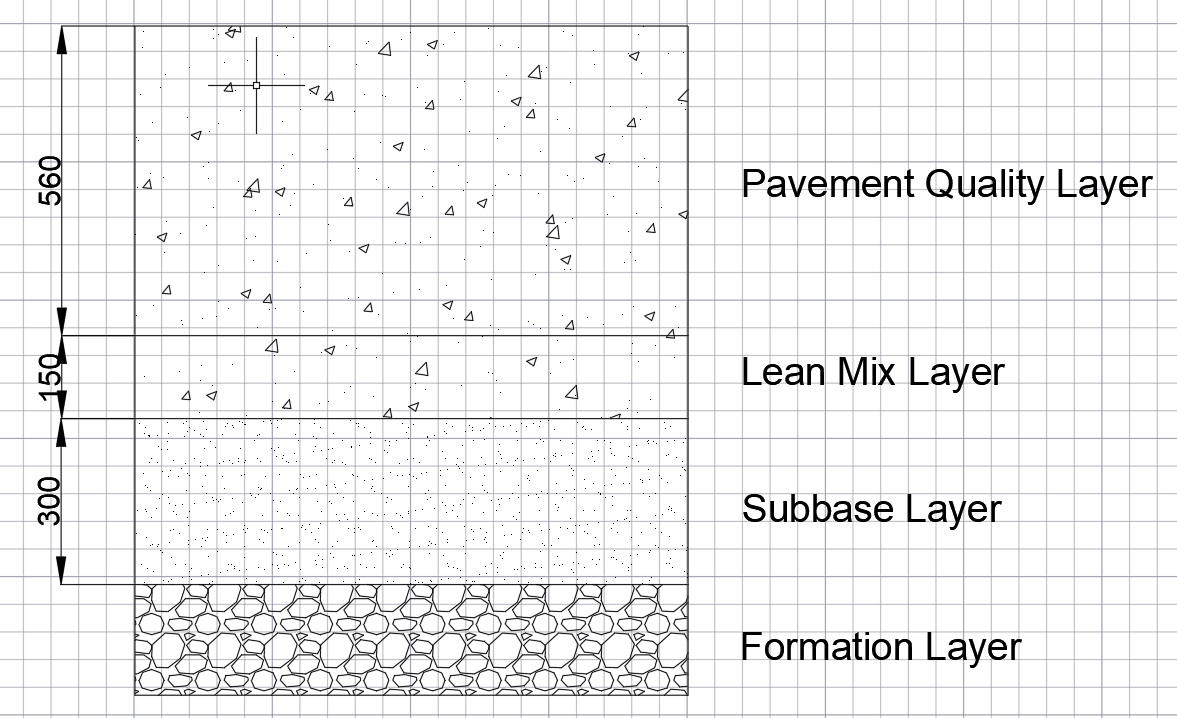
As part of the A380 stand upgrade works ongoing, the aircraft taxiway pavement is being upgraded to support the heavier loads of the A380. The pavement is of a ‘rigid’ design and has been constructed in three layers (see Figure 1): a granular subbase (300mm) with Lean mix concrete layer (150mm) with a specific Pavement Quality (PQ) mix layer (560mm). There is no reinforcement to the pavement quality layer as I understand it is assumed the concrete will be working in compression only. The concrete for the new stand is being built in sections, with one of the longest sections cast recently. This section was cast 30m in length total by 5.5m widths and then cut into 6 parts for movement joints.
It was discovered recently that a substantial crack had developed through the thickness of the PQ layer at this section. The crack is highlighted in Figure 2 below.
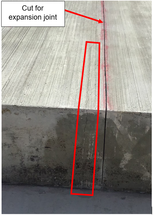
It is thought on site that the crack sits over a hard area of ground and may have formed a crack where the concrete was acting in tension. As the crack is close to the cut for the expansion joint it may be possible that the contractor waited too long before cutting the joint, resulting in the crack.
It is likely that this PQ layer will have to be broken out and cast again, as water ingress into this crack will cause future problems. The crack may have been avoided by casting the blocks in smaller sections, reducing the tension on the PQ. I would be interested to know any thoughts on this problem and any ways in which it might be resolved. Such an issue will no doubt be costly for the ground works subcontractor.
Bridge over troubling roofs (Part 1)
Hello all, the Pier 6 extension at Gatwick is still going through the RIBA 3 design stage so I thought I’d switch fire to another project in the pipeline. The International Departure Lounge (IDL) link bridge is due to be built at Gatwick in the third quarter this year. It is still in the RIBA 4 design stage with the awarded works contractors now looking at the detailed design. The purpose of the bridge is to provide a more direct route between the new code F site at Pier 5 (see my first blog post) and the departure lounge. In short it is intended to improve passenger flow to the new A380 aircraft stand. At the moment passengers have to walk an indirect route to access the Pier 5 stands which adds additional walking time, reducing flow.
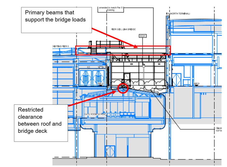
The construction of the bridge presents some interesting challenges as it is to be located in a heavily built up part of the airport. As can be seen in Figure 1 below, the location of the bridge is difficult to access for plant and equipment. Crane access is also difficult due to the size of the existing buildings, limiting prefabrication options. Therefore the building is to be stick built to account for the congested site.

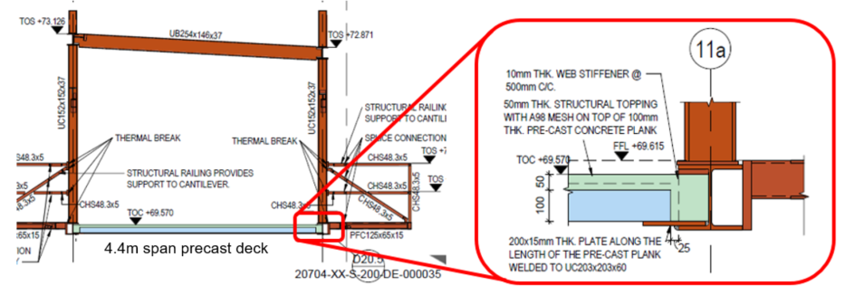
The proposed design can be seen in Figure 2 below. Due to the level of the bridge deck and the roof structure of the building underneath, the clearance of the top of decking and the top of the roof ridge is approx. 200mm. This has dictated the size of the beams that support the deck as can be seen in Figure 3 further on. This means that a traditional bridge structure where the deck beams are supported below is not feasible. The design therefore transfers the bridge loads from the deck through columns attached to two beams located above the bridge corridor. These connect to beams that span between the columns of the existing buildings.
These beams have to carry not only passengers, but also electrical passenger vehicles (up to 5kN/m2). A 100mm concrete precast decking solution using Bison beams with a 50mm screed reinforced with mesh has been specified by the designer (see Figure 3 below – Bison beams specified in notes).
Here come the problems: According to the contractor, Bison are no longer able to provide the 100mm decking solution and this issue has gone back to the designer. A composite deck with steel profiling is not possible due to deflection limitations set out in the specification (limited to span/360). The designer claims that there are no suppliers who are willing to provide a solution and a redesign is required. However, having had a quick search of suppliers myself, there do seem to be some out there who can meet the spec – maybe the designers haven’t looked hard enough? I’ve not had chance yet to enquire with the designer about this.
From the client point of view there is a reluctance to change the design to accommodate a deeper decking. The first is that by increasing the thickness of the precast concrete decking slabs, the screed would be thinner; risking cracking issues if there are deflections. I would think that this may not be an issue as the precast decking would have pre-tensioned reinforcement? However, the spec (from Gatwick) states that crack widths are limited to 0.1mm and although this seems rather excessive, maybe this is a legitimate concern.
The second reason is that in changing the design thickness of 100mm, the designer would have a reason to add delays to the design of the bridge (which is already delayed and not yet finalised). As they are on a cost reimbursable contract (the reasons for this in itself are enough for a separate discussion!) any major design changes will incur a heavy cost. I think this may be why the designer hasn’t really investigated all 100mm decking options as there is no incentive for them to do so under this kind of contract. Instead I suspect they want to use this as a reason for delay to the design schedule by significantly changing the deck design.
As a side note there are also challenges around the temporary works and scaffolding required to enable the project. However, I think this deserves its own blog post so I’ll leave you on the edge of your seats for my next exciting instalment.
How to put overweight building design on a diet?
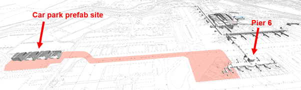
The largest project at Gatwick ongoing at the moment is the western extension to Pier 6 at the North Terminal. The project is currently at RIBA 3 (developed design) stage. In order to mitigate the impact to aircraft operations, the construction method involves building a steel structure from four separate modules off-site at a car park. It is intended that as much of the construction work is prefabricated here before the modules being moved on Self-Propelled Modular Transporters (SPMTs) across the airport to connect to the existing Pier 6 building (see Figure 1). I understand that something like this, where the whole module will be fitted out off site, has not been done before, therefore brings with it some interesting challenges.
The original module design can be seen in Figure 2 below. One of the biggest problems that has developed during the design stage has been the addition to the original module design of a significant amount of steel (1000 tons +!)[. This has largely come about due to a number of factors, one of the most significant being the key stakeholders changing their requirements part way through the project. This has meant that larger Vertical Circulation Cores (VCCs) are required, increasing the steel required for the modules.
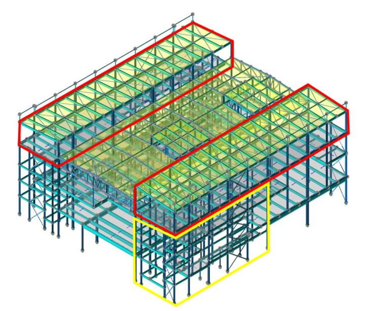
The revised design (see Figure 3) has seen the plant rooms on the roof reduced and the overall structural design simplified. Because of this simplification, larger columns and beams are now required, increasing the permanent loads despite the reduction of the plant rooms. I understand that the design was simplified for better buildability and easier ability to move by SPMT.
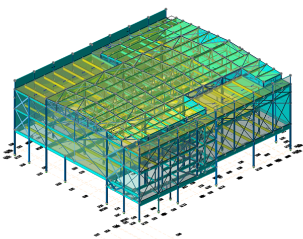
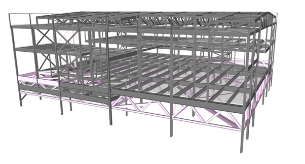
Additional temporary steel has also been required due to the need to keep the structure as rigid as possible during the SPMT move across the airfield. This has added a significant cost on top of the forecasted costs originally envisaged. Note in figure 3 that there is a lot of temporary cross-bracing to keep the structure rigid during the SPMT move. The cross bracing would prevent lateral movement though I believe it would not overcome torsional effects of the SPMT move, i.e. it would twist. Figure 4 shows a potential solution where the building sits on a truss. This uses more steel than the other design but allows the building to transfer loads much more effectively to the SPMTs.
Gatwick are negotiating with the designer on further compromises to this issue. The structural designer has added up to a 15% addition of steel to their calculations for connection detailing and 10% for ‘contingency allowance’. I’m not clear how they have come to these figures but do they seem right?
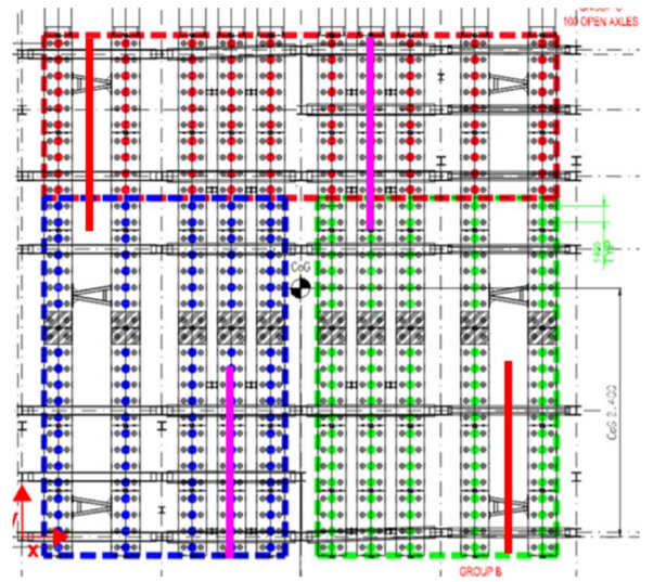
The modules also do not impose a uniform load, with the VCC part of the structure imposing more load than other areas. To mitigate this the SPMTs have been arranged in groups of three (see figure 5 below), much like the point support of a three legged wooden stool. Interestingly the module loading is distributed into four quadrants and it was originally suggested that the SPMTs also be grouped likewise. However, the SPMT contractor has stated that a four group method is not preferred due to additional control complexity during transportation.
All of this makes me wonder whether this method of construction, whilst quite innovative, has come with additional (expensive) obstacles. It may have been more economic to build the pier on site, with most of the work being done during operational stand-down hours at night. This however may have added additional time to the project. I look forward to seeing how this project evolves in the future.
Trimming your piles
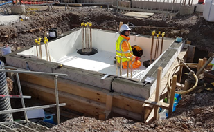
Hello all, first blog post from me (Al Bramson PET(C) 66). For those who don’t know I’m currently working at Gatwick Airport on the client side as a Project Engineer. The project I’m currently assigned to is the construction of a new passenger departure building to accommodate the A380, the big double decker plane. I’ve been inspecting some of the groundworks that has begun for this project. In particular, the pile foundations for a lift core that runs vertically through the centre of the building (see Figure 1). Kier are the subcontractor for the project and they have subcontracted the ground works to Oliver Connell.
Before Oliver Connell were to install the reinforcement cage and cast the lift pit they had left the pile reinforcement exposed (Figure 2). When I returned back to site I noticed that they had cut the pile reinforcement at the top of the pile, about 75mm above the bottom of the pile cap level. I foolishly didn’t take any photos (lesson: take lots of photos!). This cutting of rebar didn’t seem right to me as I think that there should be some reinforcement to anchor the pile to the pile cap. However, as the foundation seems to be in compression only, maybe this is not such a huge issue? The pile cap is about 1.5m deep so there is no risk of uplift as far as I can tell. Also the reinforcement cage for this is rather dense so I think they cut the pile reinforcement in order to fit the cage on top of the pile. Also possibly to save money on purchasing rebar couplers (as per Figure 4) which I understand can be collectively quite expensive.
The Senior Project Engineer seems to believe that they should have bent the rebar and definitely not cut. I checked the project drawings and they are not clear on this. I would think that the rebar would be bent if there were moments on the structure (like with a column), but the moment caused by wind loading is relatively small (bearing in mind it’s an internal lift structure). I’ve tried to research myself using the IStructE manuals with no luck. Anyone able to offer some advice?