Archive
IBM Greenford – Site Visit
Overview
IBM Greenford is a large tier 3 data centre, so it has a considerable amount of M&E equipment to keep the data centre running 24 hours a day and additional parts to increase the system redundancy in N+1 configuration. IBM has their own on site facilities management (FM) team, Kirby are the subcontractor doing the construction and Atkins provide the specialist electrical support.
I have recently visited site for a meeting regarding an issue with the new pumps being installed and to familiarise myself with the installation of the Uninterruptable Power Supply (UPS) system in the new purpose built building.
Pumps
The IBM site has an open loop industrial chiller system so the pumps supply water from an open aired tank to the chiller units. The old pumps are Worthing Simpson which are no longer available and are therefore being replaced by high efficiency Grundfos pumps.


The issue is the new pump kept going out of service and the FM team believe the pump is experiencing cavitation. The main cause of the problem is unknown; the meeting was exploring the potential causes and solutions with the contractor and an engineer from Grundfos via skype. Due to the issue with the pump, IBM want the pumps to be individually tested to confirm the performance matches the specification prior to installation and commission as soon as possible.
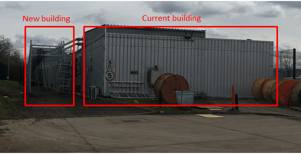
UPS
The new UPS system is being installed in a new building that has been built adjacent to the current East UPS system. Once the UPS system has been installed, each part will be individually tested before the system can be commissioned. A series of commissioning documents are currently being written by the construction team and will be reviewed by Atkins.
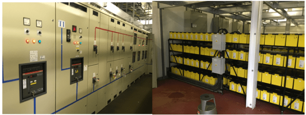
Below are some photos of the current battery rack and UPS control panels:-
Mendeley Desktop…it’s free!
Whilst writing my thesis I have found Mendeley Desktop to be an excellent reference management system and the citation plug-in for Word is well worth downloading as well. I only wish I had listened to Mark Hill and downloaded it before starting TMR 1!
Check it out – https://www.mendeley.com/
Gloucester the building not the place
Introduction
Whilst working on HPC has been interesting, there is a limited amount to learn from the experience so I have negotiated severing my involvement in the project. I have recently been working on an electrical study for a security clearance “building” located in Gloucester.
This building has critical equipment and therefore employs an Uninterruptable Power Supply (UPS) to guarantee the power supply to the data load and the cooling plant for the equipment. Unfortunately there was an electrical fault (exact cause are unknown) which caused a fire – damaging the UPS system and a distribution boards. The building is still operational utilising the UPS bypass as a temporary solution.
Replacing the damaged system, presents the client with an opportunity to increase the capacity of the building, therefore Atkins have been employed to conduct an electrical study.
A site investigation by the DV cleared electrical lead, gathered a snapshot of the electrical loads and the maximum recorded kW for each system.
Electrical Supply
Transformer 1 (TX1) – 11kV/400V rated at 800kVA
Transformer 2 (TX2) – 11kV/400V rated at 800kVA
3x Combined Cooling, Heat and Power Load (CCH) – 310kVA (N+1 configuration therefore 2 in use and 1 as backup)
Reflection
Designing a system from the start is straight forward because the designer can use design loads of the equipment and make assumptions based on justification. Making recommendations on replacing equipment without the design loads of the equipment or data of the electrical demand profile is a difficult situation. Using the maximum recorded loads identifies the worst case scenario, however combining all of these maximum will significantly reduce the extra capacity for expansion. Whilst using the electrical loads from the survey provides a more realistic figure but the survey could have been conducted during a low demand period. Therefore all the recommendations made by Atkins are caveated by “the recommendation for energy data loggers to be installed for a month to give an indication of the current kW on the system to confirm suitability prior to installation of a new load”.
It comes back to T/C/Q. The client Interserve want a quick solution – the UPS is a critical part of the system therefore its quick replacement is essential. Whilst Atkins focus on a quality product in the hope of winning more work off the back and building their reputation/relationships with the Client.
Spare capacity
Using the electrical demand provides the following spare capacities:-
TX1 –427kVA (53%)
TX2 –264kVA (33%)
2x CCHP –239kVA (38%)
It is important to understand the system operation before making recommendations on expansion. In the event of total failure of the CCHP, the load would be switched to the TX2 and the UPS would provide the supply during the transition. Therefore the potential increase of the data load by 239KVA supplied by the CCHP will limit the potential capacity of TX2.
TX1 –427kVA (53%)
TX2 –25kVA (3%)
Further Analysis
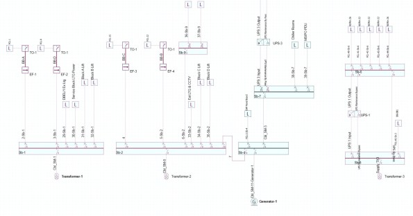
I am currently modelling the building in AMTECH (similar to Hevacomp) see picture below, in order to conduct further analysis on increasing the electrical demand and the potential limitation due to current carrying capacity of the sub-main cables and potential changes to fault protection.
Atkins – Epsom

Like the rest of the course, I have moved to a design office just before Christmas leave and had time to settle in. My phase 3 attachment is with Atkins in their Building Services division at Epsom. This short blog will be a brief introduction to Atkins and one of the projects I have been working on.
Atkins Profile
Atkins are a global multi-disciplined design consultancy providing design, engineering and project management. The company was established in 1938 by Sir William Atkins and over the next 75 years it has developed into one of the top 20 global design firms in the world. It has 18,052 staff across 300 offices in 29 different countries and a global company revenue of £1.86 billion.
Hinkley Point C (HPC)
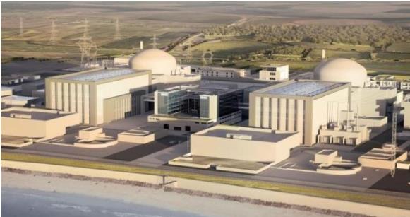
Client: EDF Energy value £1 million
Atkins involvement with the £18bn nuclear power station project is providing a Bill Of Quantities (BOQ), cable routing drawings, load schedule and lighting calculations for the ‘Small Power and Lighting Package’ for the 40 building across the site.
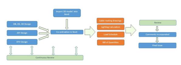
The client required a robust cost model which could be included in the Initiation To Tender to potential contractors. Atkins were extremely keen to impress the Client and decided to deliver the project through 3D modelling software Revit.
Project Process
In order to setup the 3D model, the CAD team imported the 3D files for all the Structural, Architectural and Building Services information. The CAD team created families of symbols to represent the different types of cables, containments and fittings which would enable the accurate generation of BOQ.
The engineers used the layout information from the General Arrangement drawings, designed the cable routes and manually added the families of symbols into the 3D revit model for each of the buildings.
3D Cost Model
The picture below shows the 3D model for the small power (DX) supplying the Data and Audio system within one room. Cables have been drawn from the electrical devices, above the secondary containment and primary containment to the distribution boards.
Blue – standard trunking various sizes, Red – fire rated trunking various sizes , Light Green – Primary Containment
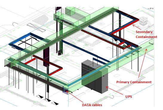
The output from the 3D cost model: total number of devices, total length of secondary containment and total cable length. The cable lengths are higher than initially estimated by the designer because of the requirement to have separate routes for each device, increasing the redundancy within the systems. The picture below is showing the cable lengths for the same room above.

Conclusion
Revit is quite simple and easy to use. It is much easier than Autocad and similar to the other 3D modelling or CAD software used in Phase 1. The difficult part I have seen is initially setting the project up and resolving issues which have all been managed by the BIM technicians. Revit provides a higher quality product and it currently takes longer to create due to the input into the model which will increase overall cost.
Using Revit has enabled Atkins to outsource parts of the work to its design centre in India, but this has required a more in-depth review of their work.
http://www.atkinsglobal.co.uk/en-GB/media-centre/news-releases/2013/group/2013-02-20
Who turned off the power?
Situation
Laing O’Rourke (LOR) originally constructed the original substructure (75% of the 3 floor Basements) and installed the Temporary Building Supply (TBS) consisting of an enclosure and network substation. It was positioned in an area that would not conflict with the original substructure works but it would need to be moved before LOR returned to site to complete the substructure.

Reflection
Brookfield inherited the site from LOR and have been entirely focused on the construction of the tower. In the process they have neglected to carry out sufficient analysis regarding the temporary power and realising the potential impact. The TBS and RMU should have been moved earlier in the programme or the temporary power layout should have considered the future move.
Instead the project has progressed and increased the impact of the pending change by having more steel wire armoured (SWA) cables installed directly from the Ring Main Unit (RMU) to the large plant, cranes and hoists, wet riser system and welfare facilities.
Issue
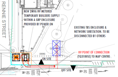
Power On (HV specialist) and UK Power Networks (District Network Operator) were required to do the majority of the works to install the new TBS (1x 2MVA transformer). In order to switch the HV connection from the old TBS all the power to the site needed to be isolated.
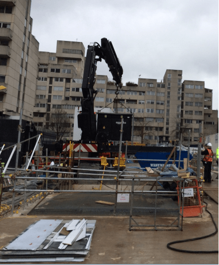
Mitigation
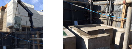
In order to reduce the impact of the power outage the option of hiring 2x 500kVA generators was taken. The problem of siting 2x generators on a construction site was finding 6m2 of flat ground with enough strength from the concrete slab. The area North of the new TBS was identified, Aggreko (generator sub-contractor) visited the site, agreed to install the generators with extra fuel capacity by conducting the lift from Rennie Street.
When Aggreko delivered the generators, the Crane Op was unable to place the generators from Rennie Street. Therefore the decision was taken to conduct the lift from the pit lane and site one generator. It caused problems for the deliveries on that day but ultimately prevented a larger problem from unfolding.
Environmental
This was raised and checked by the Environmental specialist on site:-
From 1st September 2015 construction projects within the Greater London Area are required comply with the London Low Emission Zone Non-Road Mobile Machinery (NRMM) requirements. All NRMM with an engine net power between 37kW and 560kW must meet minimum standards in terms of exhaust of Nitrogen Oxides and Particulate Matter. All qualifying plant must be recorded in an online register and those that do not meet the require standard have to be replaced.
Anyone else experienced any emissions restrictions?
London Skyline
Introduction
After a few weeks working on site and a trip to Borneo it is time for a blog. I’m currently working for Brookfield Multiplex (BM) on One Blackfriars Road (OBR) in central London. BM specialises in constructing high rise buildings or in their own corporate words “We build skylines London/Dubai/Sydney…”.


Overview
BM are constructing a 50 storey residential tower to shell and core status, hotel including fit out and a 4 storey retail podium including all the Mechanical Electrical and Public Health (MEP). Below the entire site is a 3 storey basement which contains all the centralised building services, hotel swimming pool and some very expensive parking spaces.
Shell and Core Status
Shell and core for the tower comprises of the structure, façade, common areas, external works and base plant.
The base plant is mostly M&E and includes:-
- High and low voltage switchgear.
- Transformers.
- Lift systems.
- A standby generator.
- Boilers.
- Chillers.
- Cooling towers.
- Water and fuel tanks.
- Sprinkler plant.
- Building control systems.
- Air conditioning chambers and fans.
- Water and fuel pumps.
- Dry risers.
- Fire detection, alarm and hose reel systems.
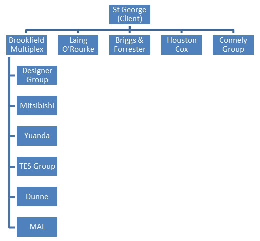
The Client
The client is St George part of the Berkley Group and they are a very ‘hands on’ client with their own project management team on site to manage their own sub-contractors and BM (Principal Contractor). All communication for St George’s subcontractors has to go via the client, which makes it slightly more difficult for BM to effectively manage the entire site. St George are heavily involved with significant developments requiring approval such as jumping the crane, site access and storage, and changing over the power supply from one substation to another.
Role
I have been given the role of Assistant MEP Site Manage and are responsible for managing the installation of the following systems within the Tower and Basement:-
- Condenser system.
- Domestic water.
- Wet riser system.
- Low temperature hot water.
- Low voltage power distribution.
- Heating, ventilating and air-conditioning system.
- Combined heat power.
- Lift systems.
Sectional Handover
The Tower is broken down into sections of 2 to 3 floors and a new section is handed over to the Client almost every 3 weeks. Therefore I’ve been heavily involved with managing the installation and the MEP handover for Section 2&3.
BM have handed over Sections 1-3 and are currently working on Section 4 but the Client has failed to accept any of Sections and it places the liquidated and ascertained damages for the 3 Sections at circa £105k per day. The main issue is the façade and the Client is refusing to inspect the outer façade because they believe it to be dirty and then they have refused to inspect the inside façade because of the outer. Still to be resolved.
View from Level 25
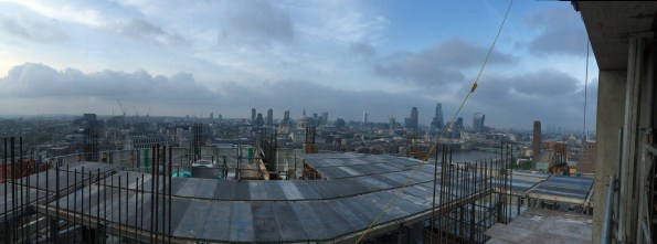
The 5 storey penthouse is still for sale…
Regards
Alex
